13–92 CHAPTER 13. The Laplace Transform in Circuit Analysis
[e] The s-domain equivalent circuit for t>0 is
P 13.92 [a] Z1=1/C1
s+1/R1C1
=25 ×1010
s+20×104Ω;
Problems 13–93
K1=2(200,000)
50,000 = 8;
[b] I0=V0
Z2
=2(s+ 200,000)(s+12,500)
s(s+50,000)6.25 ×10¹⁰
[c] When C1= 64 pF
Z1=156.25 ×10⁸
s+12,500 Ω
P 13.93 Let a=1
R1C1
=1
R2C2
.
13–94 CHAPTER 13. The Laplace Transform in Circuit Analysis
VoC2(s+a)+V0C1(s+a) = (10/s)C1(s+a);
P 13.94 [a] The circuit parameters are
Ra=1202
1200 = 12 ΩRb=1202
1800 =8ΩXa=1202
350 =288
7Ω.
The branch currents are
Therefore,
[b] Begin by using the s-domain circuit in Fig. 13.60 to solve for V0
symbolically. Write a single node voltage equation:
Problems 13–95
[c] The phasor domain equivalent circuit has a j1Ωinductive impedance in
series with the parallel combination of a 12 Ωresistive impedance and a
j1440/35 Ωinductive impedance (remember that ω= 120πrad/s). Note
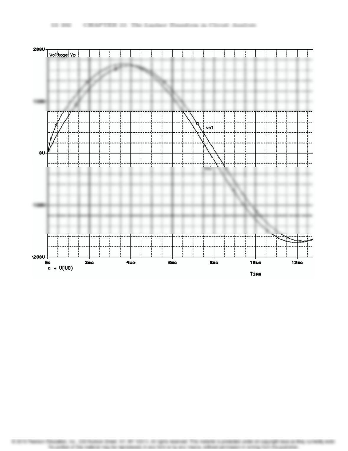
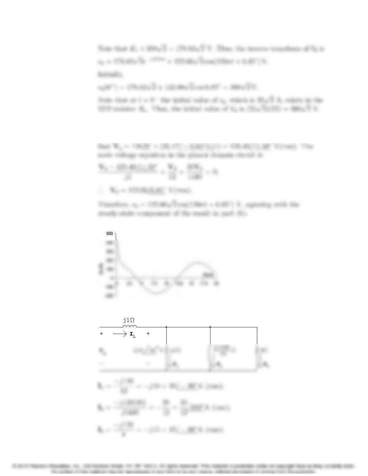
[d] A plot of v0, generated in Excel, is shown below.
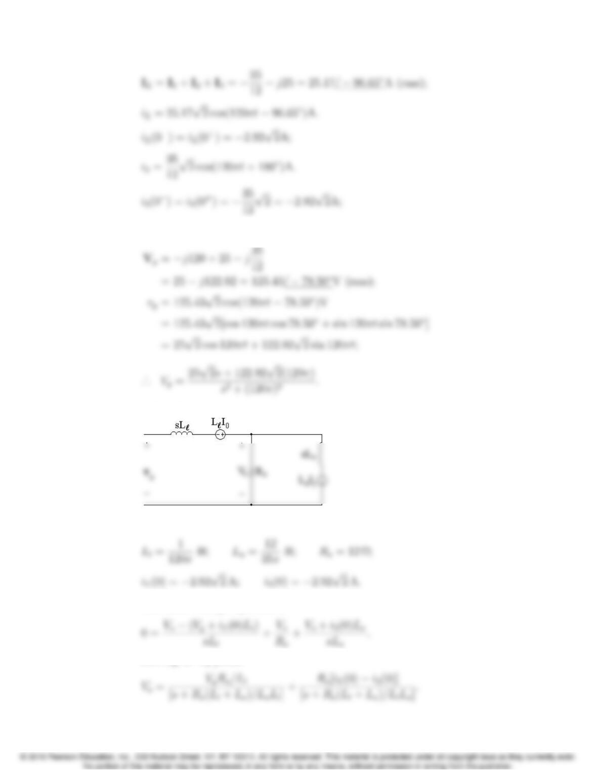
P 13.95 [a] At t=0
the phasor domain equivalent circuit is
13–96 CHAPTER 13. The Laplace Transform in Circuit Analysis
Vg=Vo+j1IL;
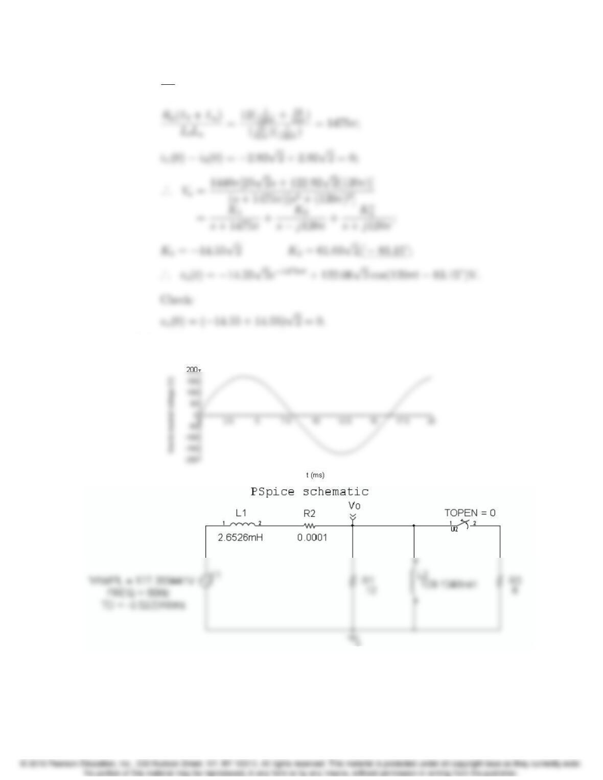
s-domain circuit:
where
The node voltage equation is
Solving for Voyields
Problems 13–97
Ra
Ll
= 1440π;
[b]
13–98 CHAPTER 13. The Laplace Transform in Circuit Analysis
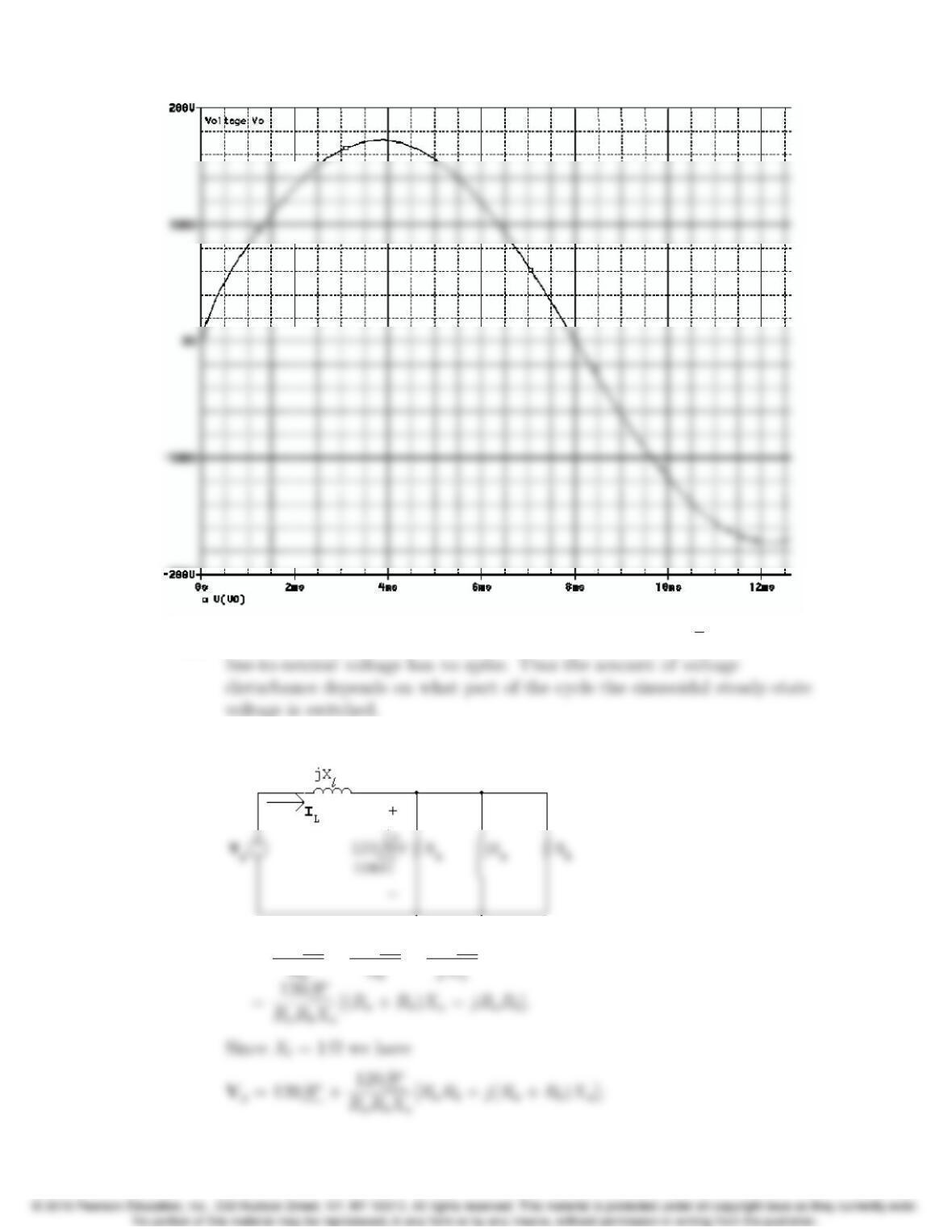
[c] In Problem 13.94, the line-to-neutral voltage spikes at 300√2 V. Here the
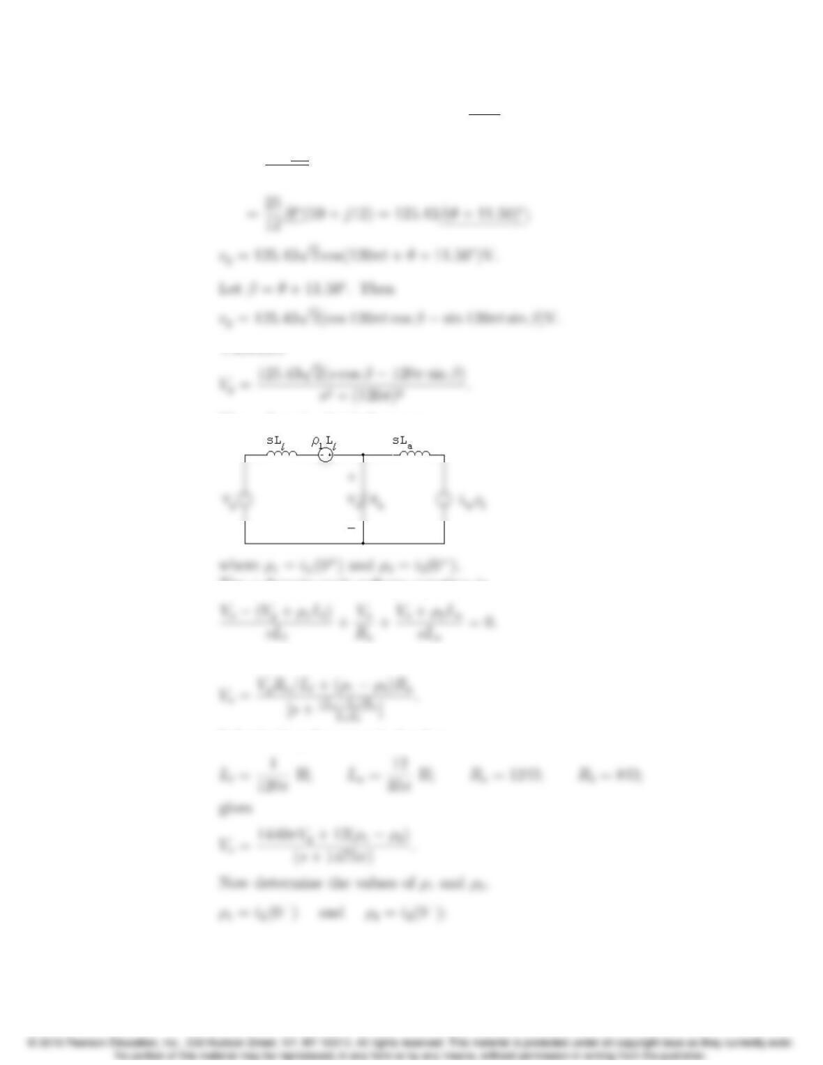
P 13.96 [a] First find Vgbefore Rbis disconnected. The phasor domain circuit is
IL=120/θ
+120/θ
+120/θ
Problems 13–99
Ra= 12 Ω;Rb= 8 Ω;Xa=1440
35 Ω;
Vg=120/θ
1400 (1475 + j300)
The s-domain circuit becomes
The s-domain node voltage equation is
Solving for Voyields
Substituting the numerical values
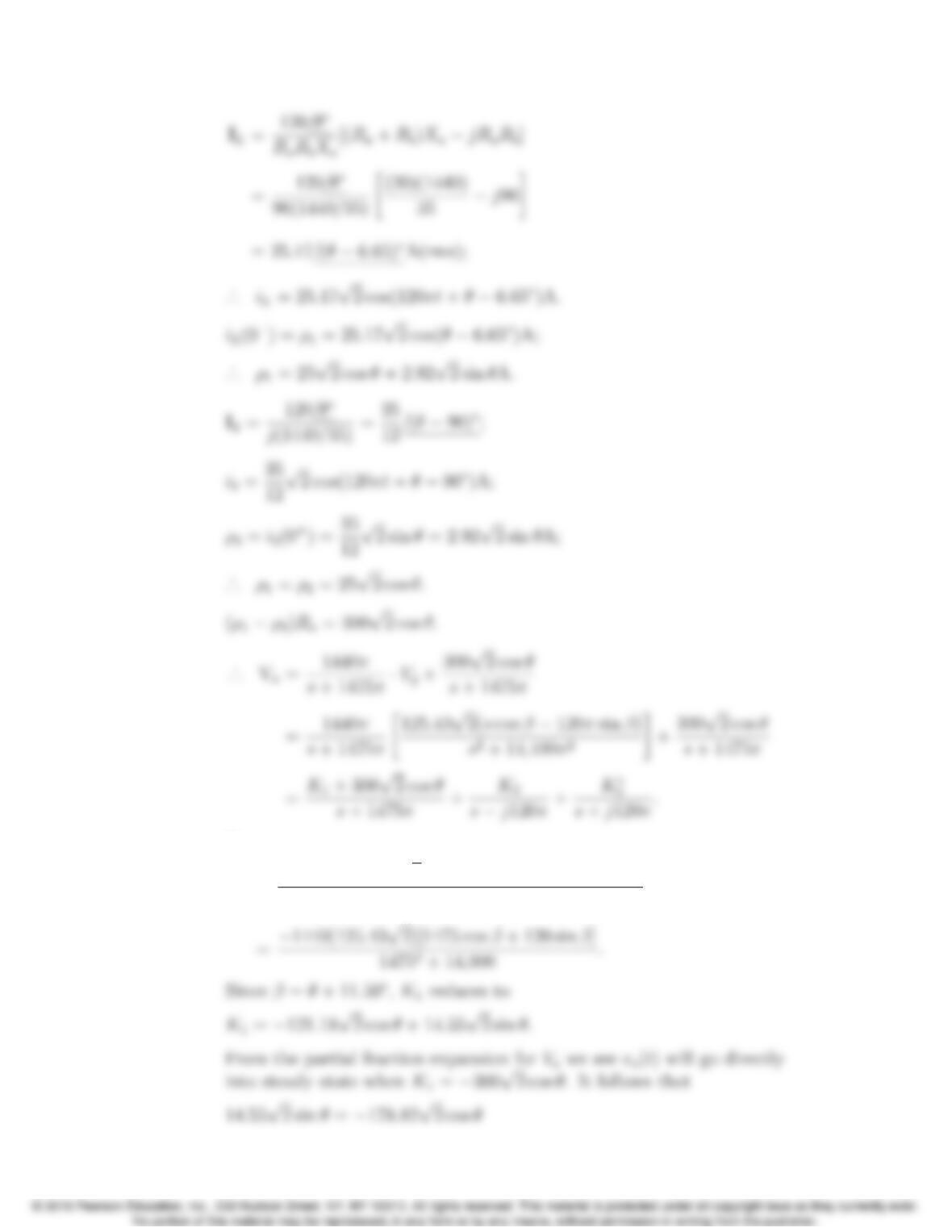
13–100 CHAPTER 13. The Laplace Transform in Circuit Analysis
Now
K1=(1440π)(125.43√2)[−1475πcos β−120πsin β]
14752π2+14,400π2
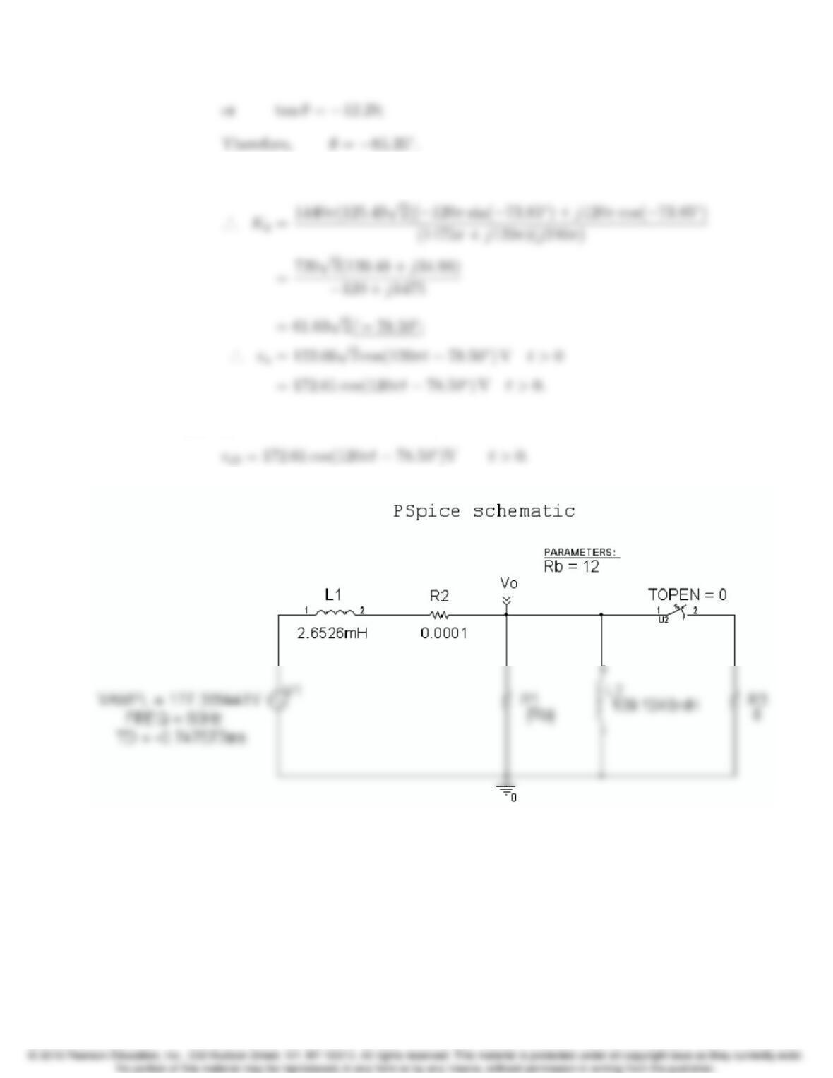
Problems 13–101
[b] When θ=−85.35,β=−73.85.
[c] vo1= 169.71 cos(120πt−85.35)V t<0;