The Laplace Transform in Circuit
Analysis
Assessment Problems
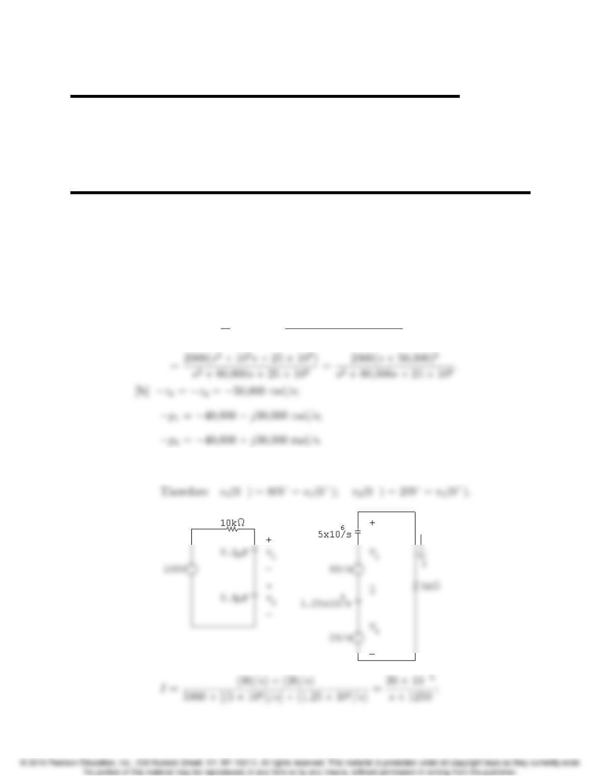
AP 13.1 [a] Z= 2000 + 1
Y= 2000 + 4⇥107s
s2+80,000s+25⇥108
AP 13.2 [a] At t=0
,0.2v1= (0.8)v2;v1=4v2;v1+v2= 100 V;
13–1
13
13–2 CHAPTER 13. The Laplace Transform in Circuit Analysis
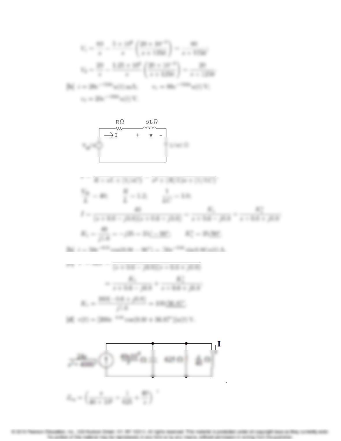
AP 13.3 [a]
AP 13.4 Transforming the circuit into the sdomain for t>0:
Problems 13–3
=40 ⇥106s
s2+64,000s+16⇥108;
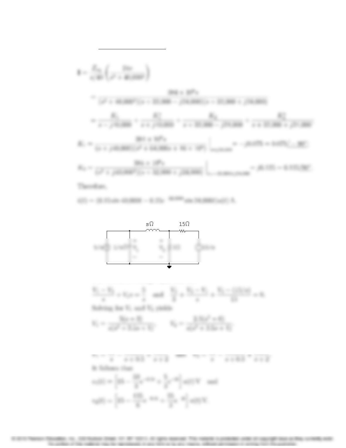
AP 13.5 [a]
The two node voltage equations are
[b] The partial fraction expansions of V1and V2are
13–4 CHAPTER 13. The Laplace Transform in Circuit Analysis
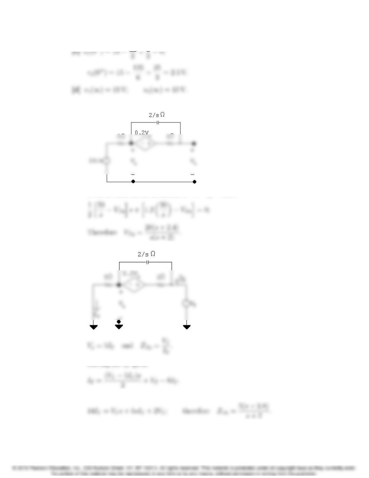
AP 13.6 [a]
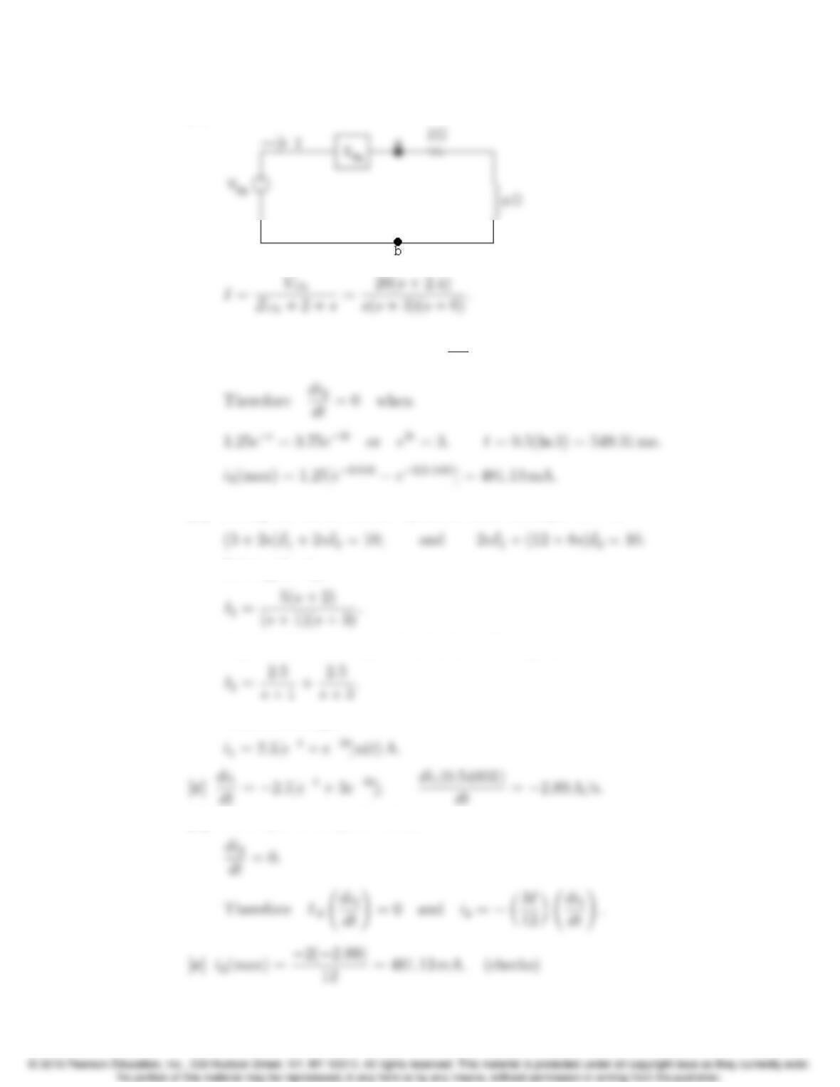
With no load across terminals abV
x= 20/s:
Therefore
Problems 13–5
[b]
AP 13.7 [a] i2=1.25et1.25e3t; so di2
dt =1.25et+3.75e3t.
[b] Solving the mesh current equations from Example 13.7 are
Solving for I1,
A partial fraction expansion leads to the expression
Therefore we get
[d] When i2is at its peak value,
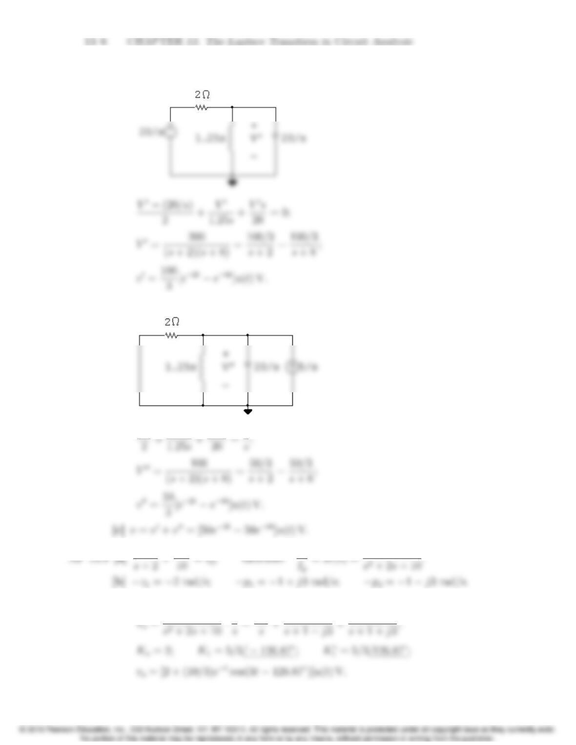
AP 13.8 [a] The s-domain circuit with the voltage source acting alone is
[b] With the current source acting alone,
V00
AP 13.10 [a]
1
Problems 13–7
2
AP 13.11 [a]
H(s)=L{h(t)}=L{vo(t)}
[b] Vo(s)=H(s)·1
s=9600
s2+ 140s+62,500
AP 13.12 From Assessment Problem 13.9:
H(s)= 10(s+2)
AP 13.13 [a]
13–8 CHAPTER 13. The Laplace Transform in Circuit Analysis
[b] Replacing R2by Rxgives us H(s)=RxCs 1
RxCs +1.
Therefore
Problems 13–9
Problems
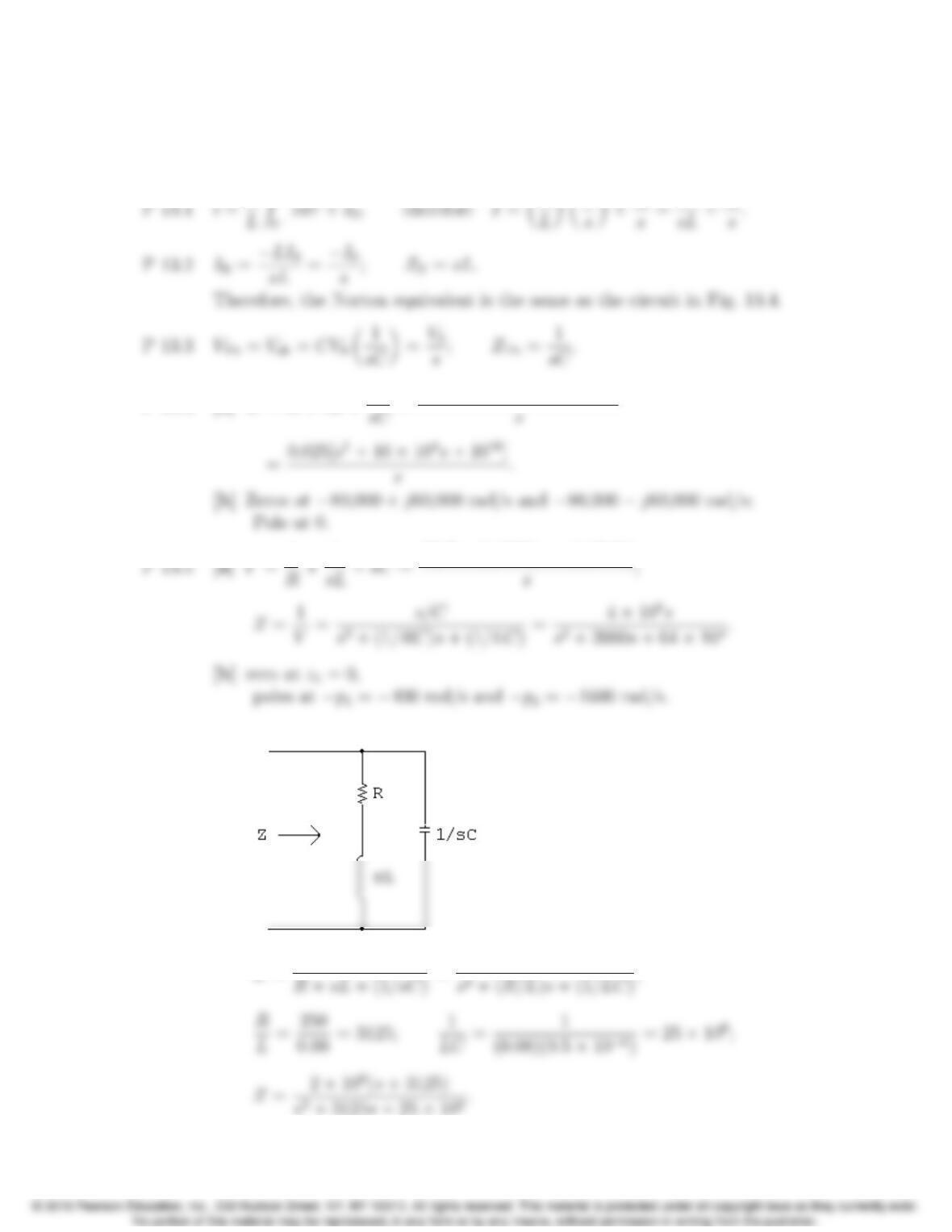
P 13.4 [a] Z=R+sL +1
P 13.6 [a]
Z=(R+sL)(1/sC)
13–10 CHAPTER 13. The Laplace Transform in Circuit Analysis
[b] Z=2⇥106(s+ 3125)
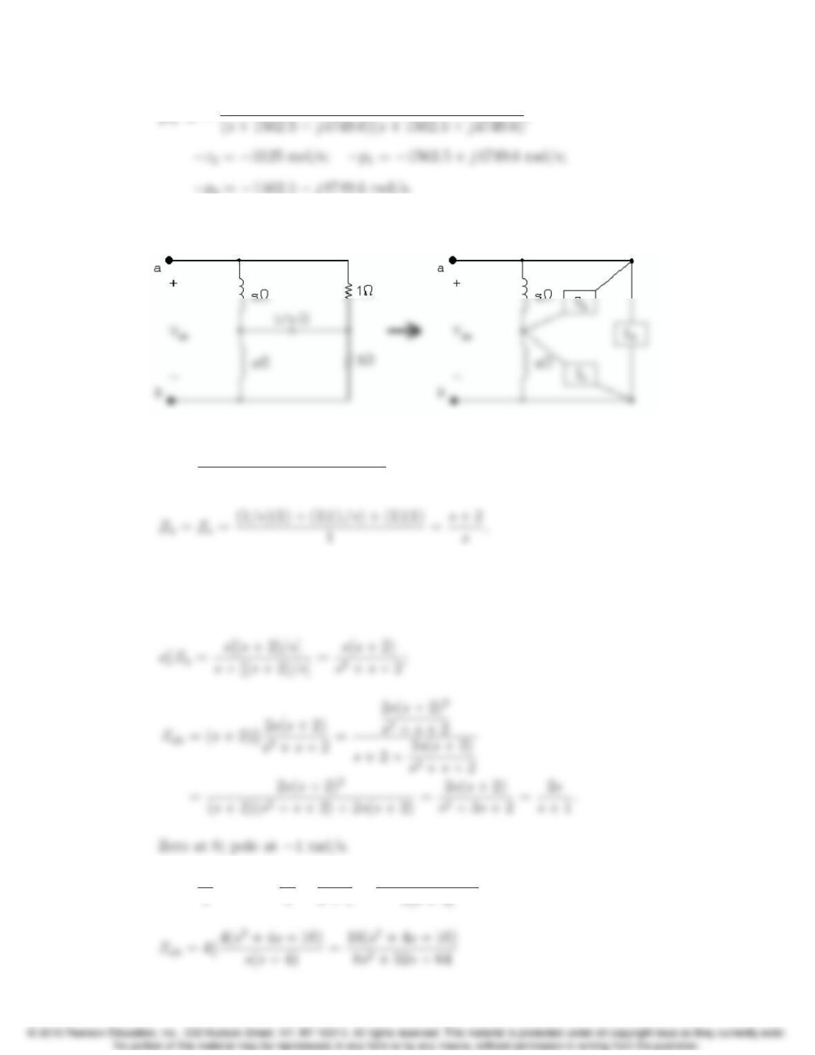
P 13.7 Transform the Y-connection of the two resistors and the capacitor into the
equivalent delta-connection:
where
Za=(1/s)(1) + (1)(1/s) + (1)(1)
(1/s)=s+2;
Then
Zab =Zak[(skZc)+(skZb)] = Zak2(skZb);
P 13.8 Z1=16
Problems 13–11
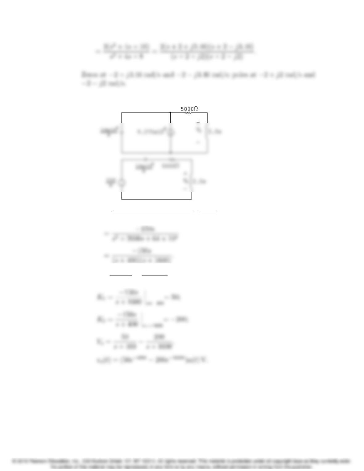
P 13.9 [a] For t>0:
[b] Vo=2.5s
(16 ⇥105)/s + 5000 + 2.5s✓150
s◆
[c] Vo=K1
s+ 400 +K2
s+ 1600.
13–12 CHAPTER 13. The Laplace Transform in Circuit Analysis
P 13.10 [a] io(0)= 20
4000 = 5 mA.
P 13.11
Vo=5⇥106/s
Problems 13–13
=15 ⇥108
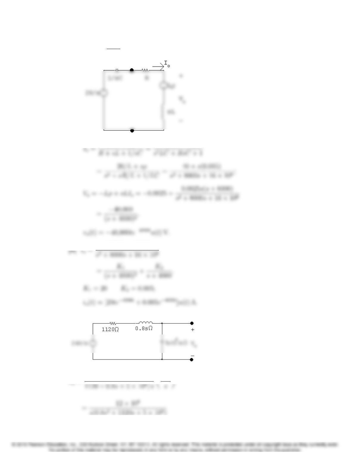
P 13.12
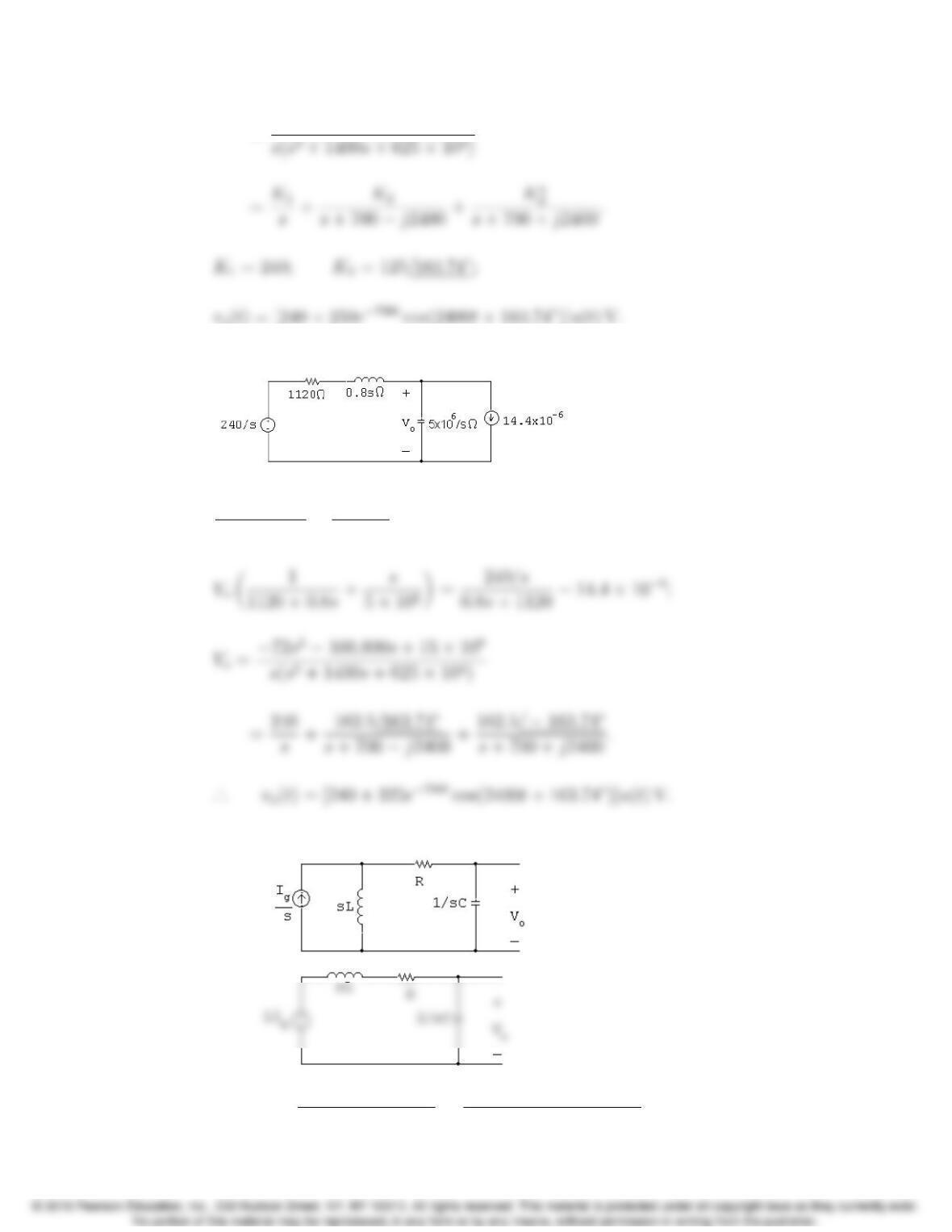
Vo240/s
1120 + 0.8s+Vos
5⇥106+14.4⇥106= 0;
P 13.13 [a]
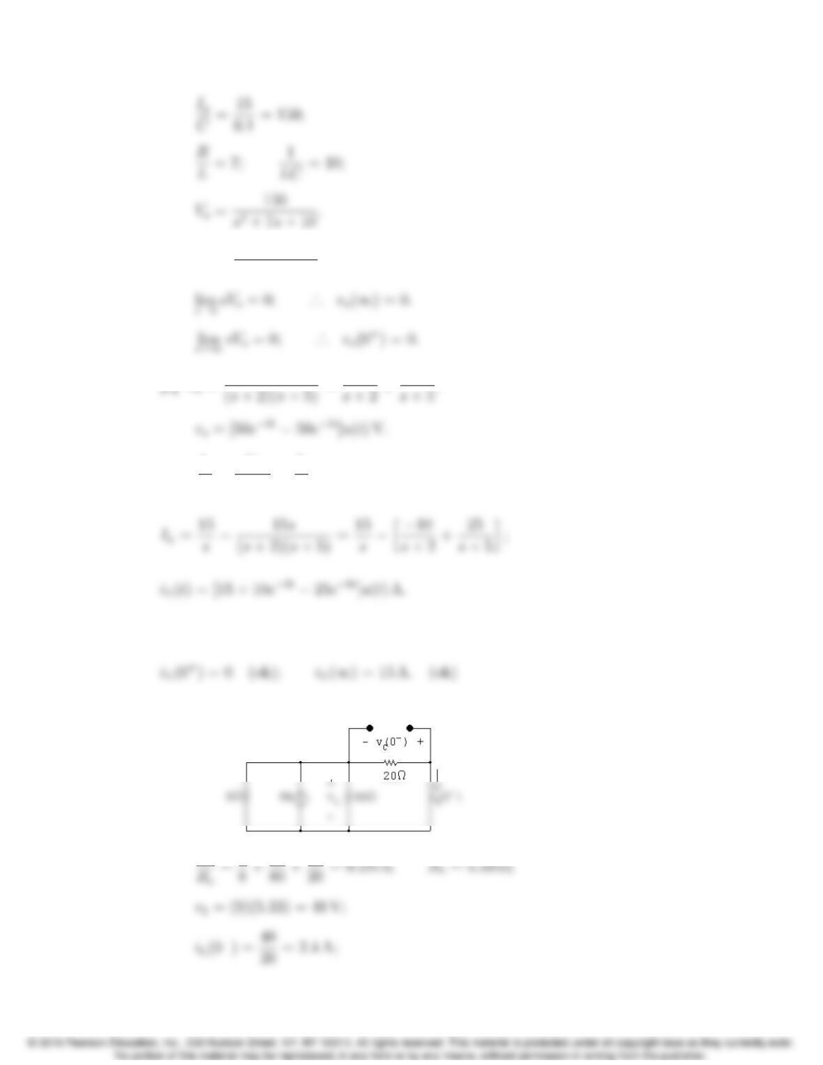
Vo=(1/sC)(sL)(Ig/s)
R+sL + (1/sC)=Ig/C
s2+ (R/L)s+ (1/LC);
13–14 CHAPTER 13. The Laplace Transform in Circuit Analysis
[b] sVo=150s
s2+7s+10;
[c] Vo=150
P 13.14 IL=Ig
sVo
1/sC =Ig
ssCVo;
Check:
P 13.15 [a] For t<0:
1
Problems 13–15
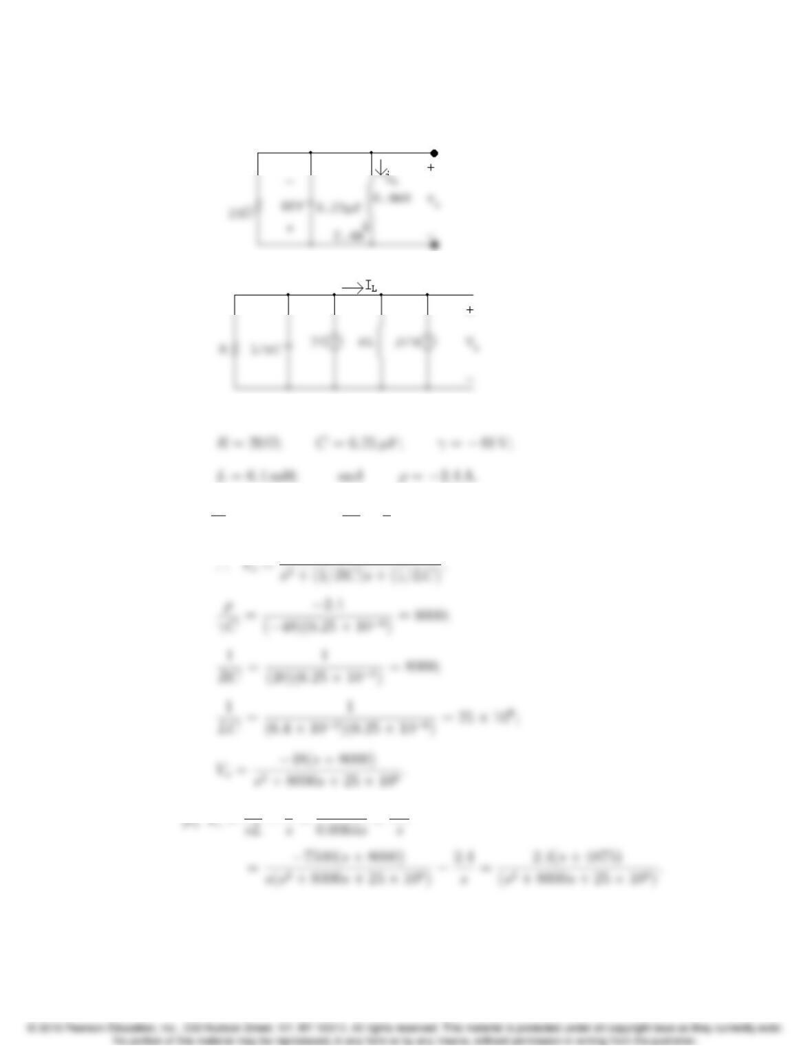
vC(0)=v1=48 V.
For t=0
+:
s-domain circuit:
where
[b] Vo
R+VosC γC+Vo
sL ρ
s= 0;
13–16 CHAPTER 13. The Laplace Transform in Circuit Analysis
[d] Vo=48(s+ 8000)
s2+ 8000s+25⇥106
[e] IL=2.4(s+ 4875)
s2+ 8000s+25⇥106
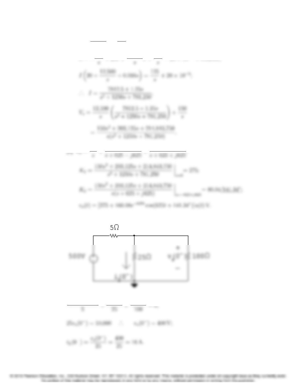
P 13.16 [a] For t<0:
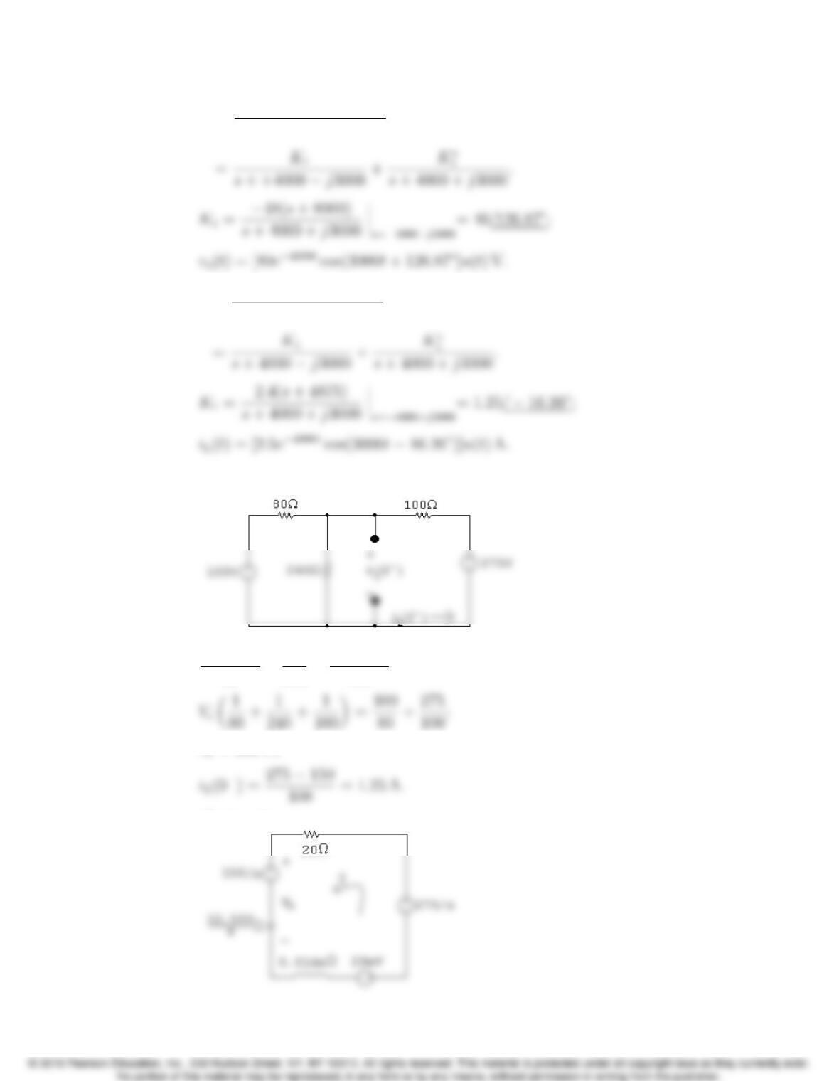
Vc100
80 +Vc
240 +Vc275
100 = 0;
Vc= 150 V;
For t>0:
Problems 13–17
[b] Vo=12,500
sI+150
s;
2
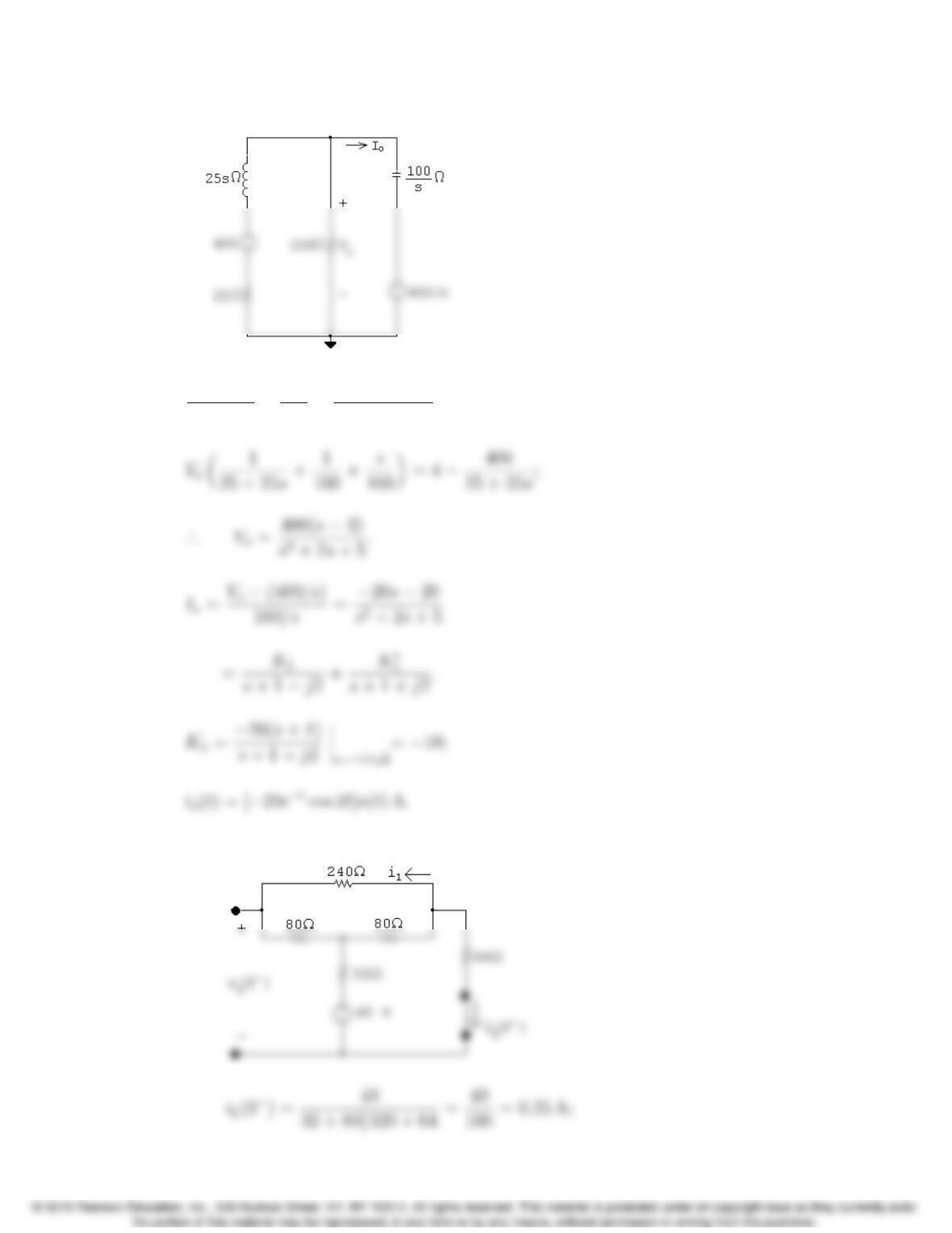
P 13.17 For t<0:
vo(0)500
13–18 CHAPTER 13. The Laplace Transform in Circuit Analysis
For t>0:
Vo+ 400
25 + 25s+Vo
100 +Vo(400/s)
100/s = 0;
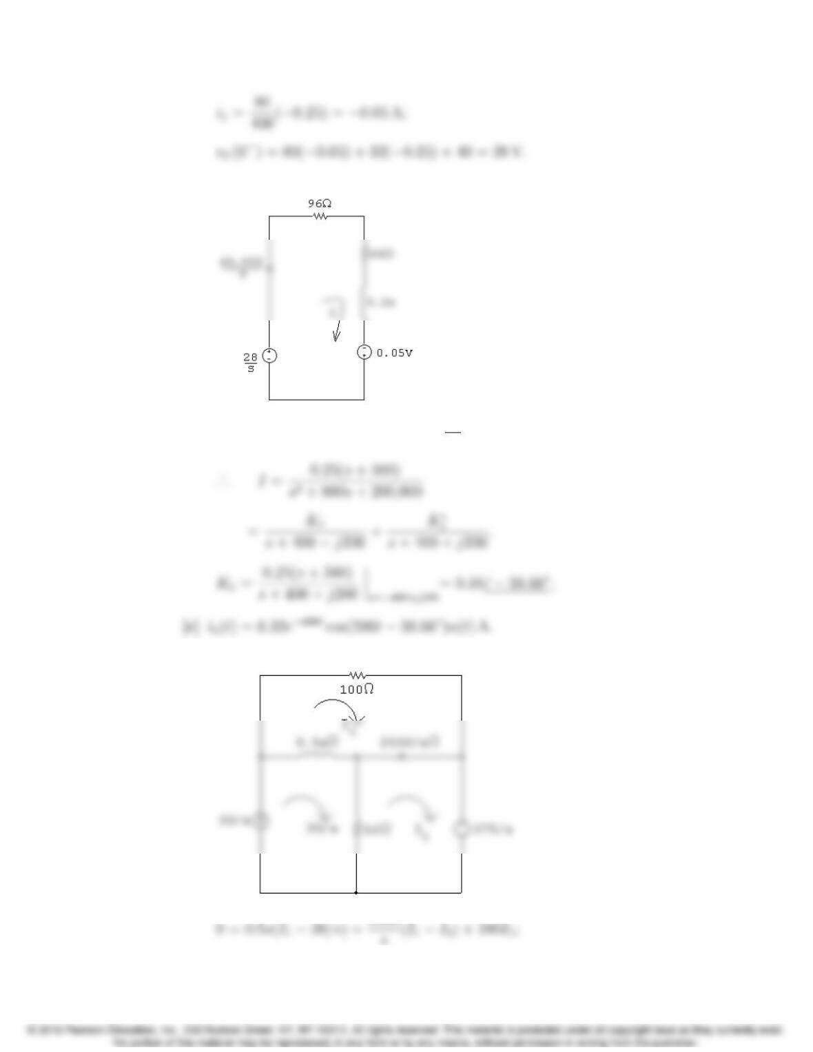
P 13.18 [a] For t<0:
Problems 13–19
For t>0:
[b] (160 + 0.2s+40,000/s)I=0.05 + 28
s;
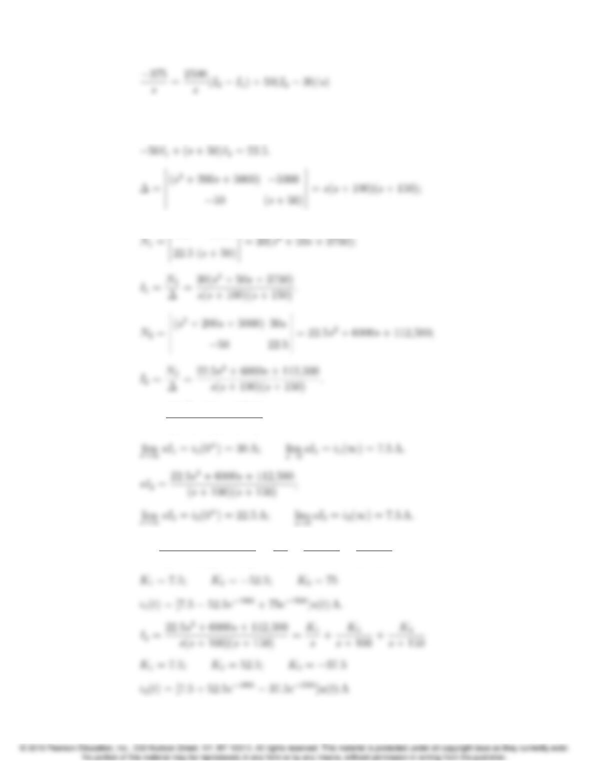
P 13.19 [a]
13–20 CHAPTER 13. The Laplace Transform in Circuit Analysis
or
(s2+ 200s+ 5000)I15000I2= 30s;
30s5000
[b] sI1=30(s2+50s+ 3750)
(s+ 100)(s+ 150)
[c] I1=30(s2+50s+ 3750)
s(s+ 100)(s+ 150) =K1
s+K2
s+ 100 +K3
s+ 150