Problems 13–81
Alternate:
Ig=Z4⇥10−3
0(10 ⇥103)est dt +Z6⇥10−3
4⇥10−3(20 ⇥103)est dt
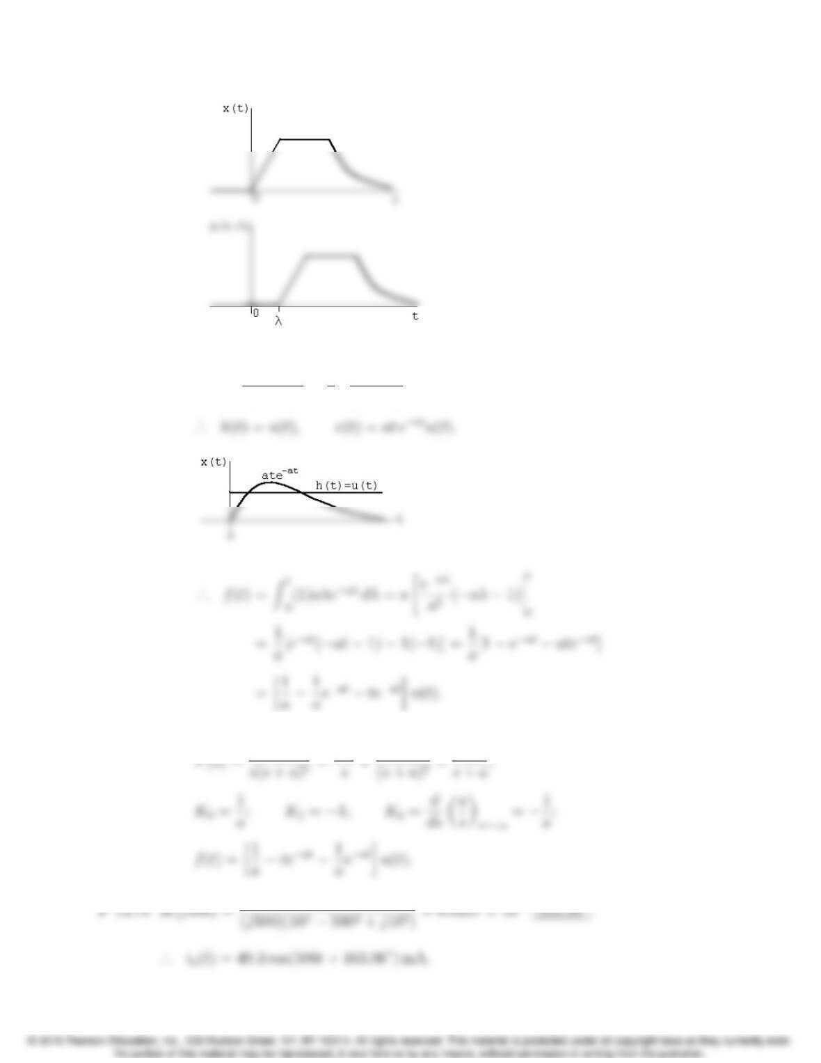
P 13.77 [a] Y(s)=Z1
0y(t)est dt.
Y(s)=Z1
0est Z1
0h(λ)x(tλ)dλdt
=Z1
13–82 CHAPTER 13. The Laplace Transform in Circuit Analysis
[b] F(s)= a
s(s+a)2=1
s
·
a
(s+a)2=H(s)X(s);
Check:
Problems 13–83
P 13.79 H(j3) = 4(3 + j3)
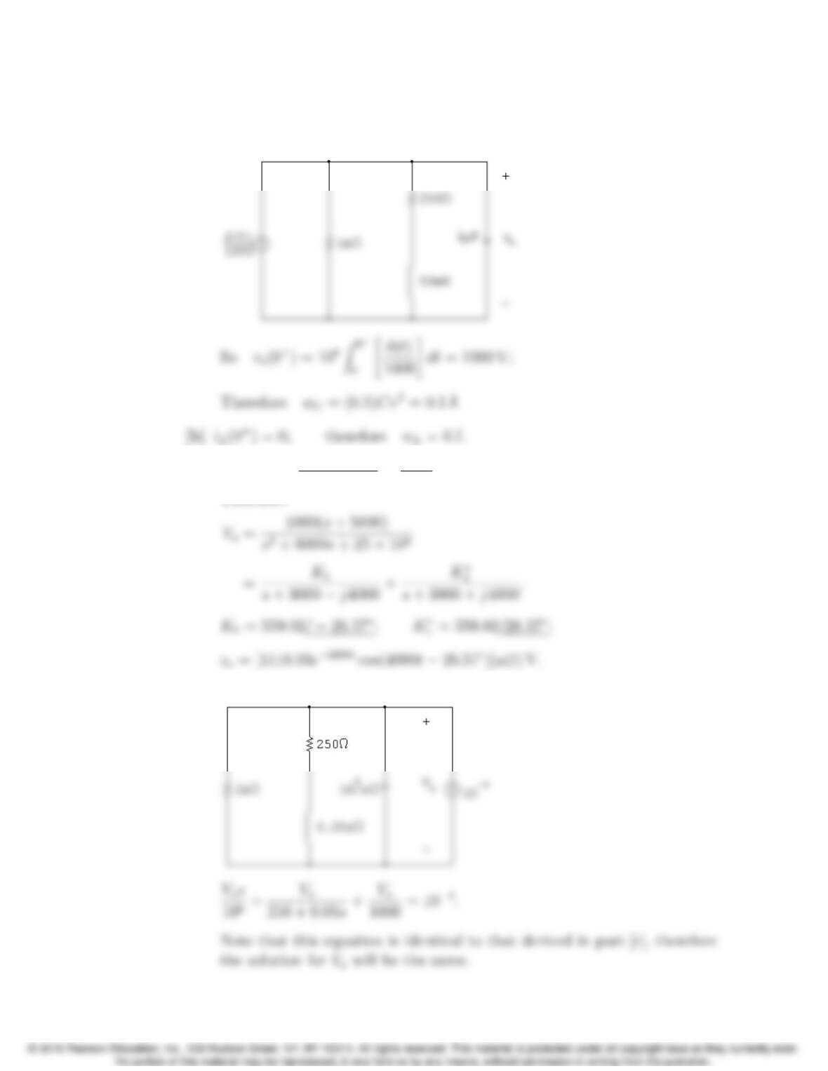
P 13.80 Vo=50
s+ 8000 20
s+ 5000 =30(s+ 3000)
(s+ 5000)(s+ 8000);
P 13.81 [a]
Vp=0.01s
80 + 0.01sVg=s
s+ 8000Vg;
Vn=Vp;
13–84 CHAPTER 13. The Laplace Transform in Circuit Analysis
[b] vg=0.6u(t); Vg=0.6
s;
[c] Vg= 2 cos 10,000tV;
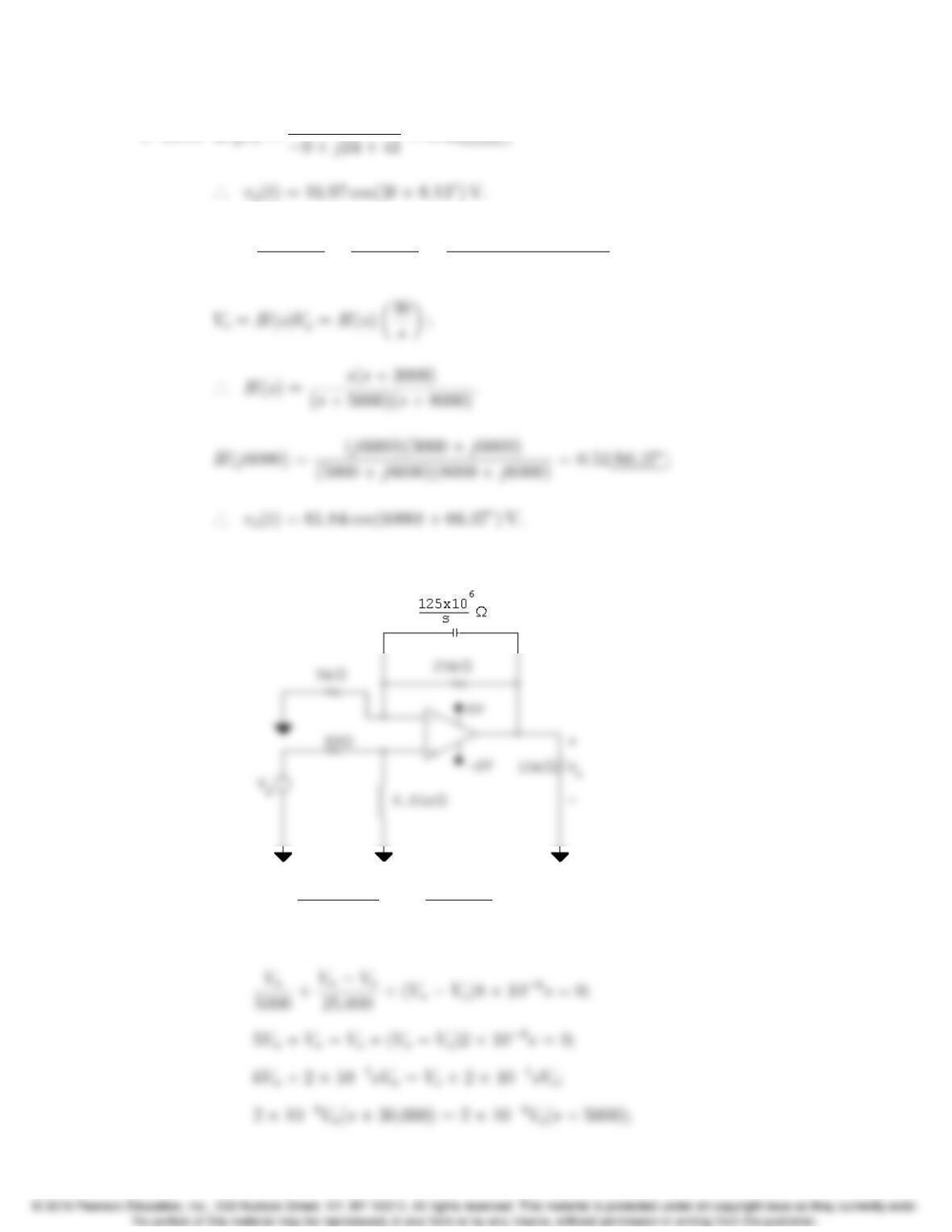
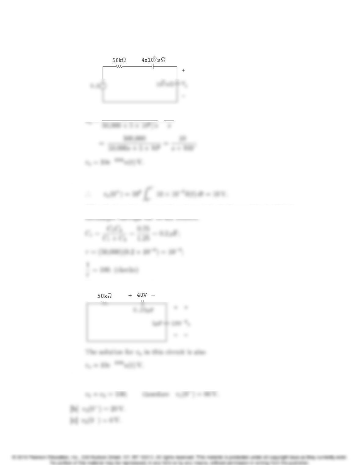
P 13.82 [a] H(s)=Zf
Zi
;
Zf=(1/Cf)
s+ (1/RfCf)=108
s+ 1000;
P 13.83 Original charge on C1;q1=V0C1.
Problems 13–85
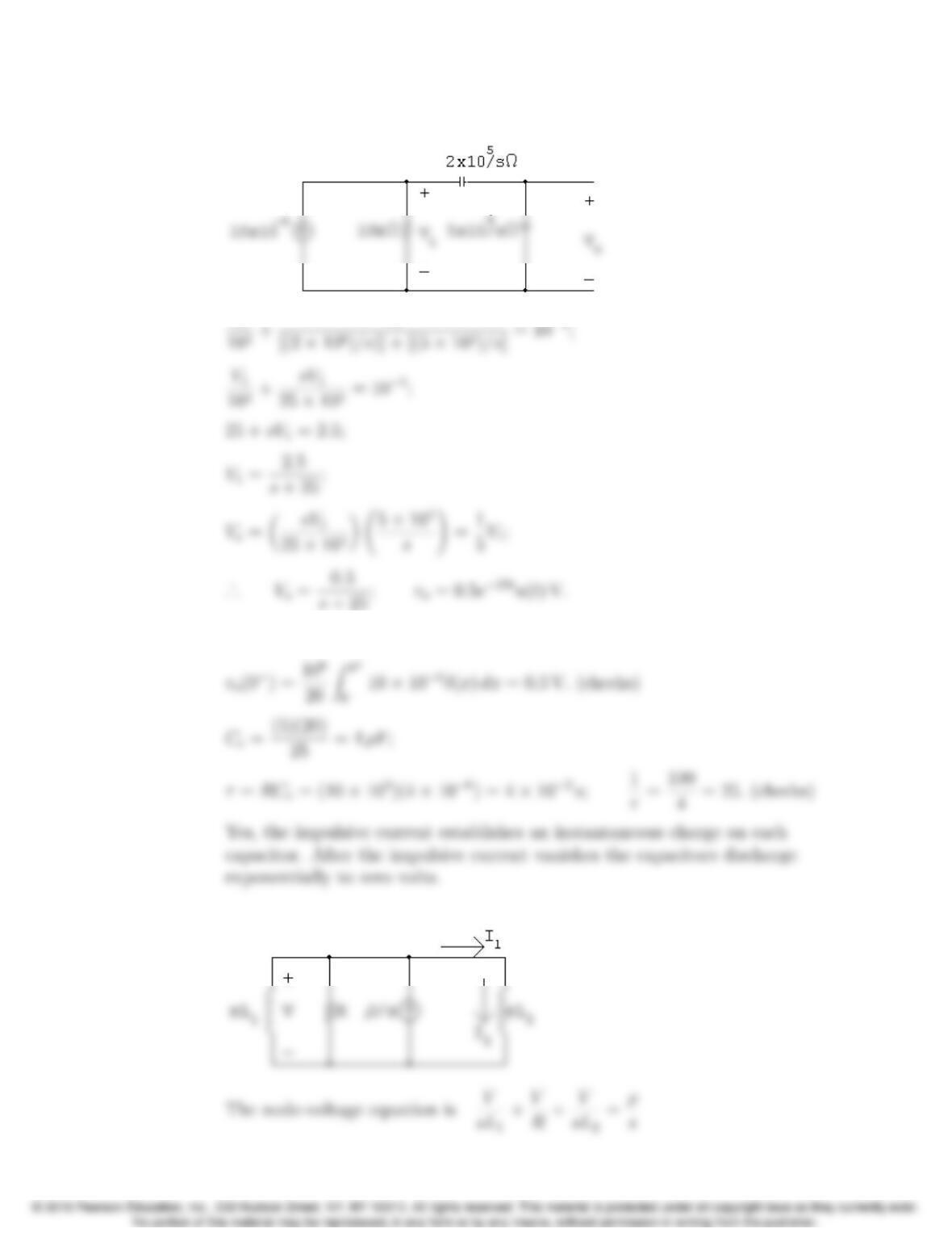
P 13.84 [a] After making a source transformation, the circuit is as shown. The
impulse current will pass through the capacitive branch since it appears
as a short circuit to the impulsive current,
[c] Vo(106)s+Vo
250 + 0.05s+Vo
1000 = 103;
Therefore
[d] The s-domain circuit is
13–86 CHAPTER 13. The Laplace Transform in Circuit Analysis
P 13.85 [a]
V1
[b] vo(0+)=0.5 V;
P 13.86 [a] The s-domain circuit is
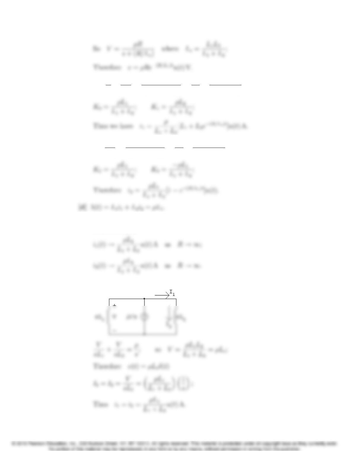
Problems 13–87
[b] I1=V
R+V
sL2
=ρ[s+(R/L2)]
s[s+(R/Le)] =K0
s+K1
s+(R/Le).
[c] I2=V
sL2
=(ρR/L2)
s[s+(R/Le)] =K2
s+K3
s+(R/Le).
P 13.87 [a] As R!1,v(t)!ρLeδ(t) since the area under the impulse generating
function is ρLe.
[b] The s-domain circuit is
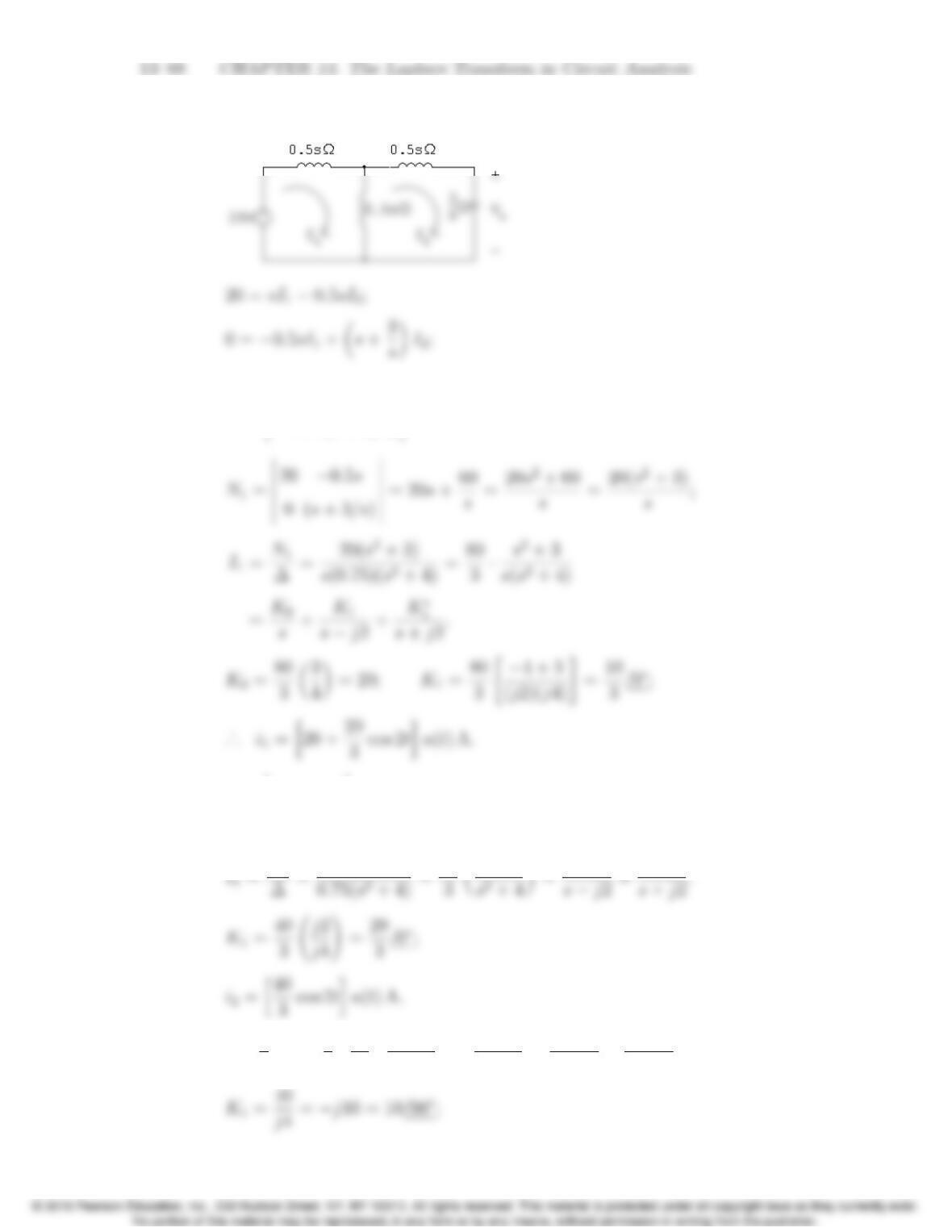
P 13.88 [a]
∆=
s0.5s
0.5s(s+3/s)
=s2+30.25s2=0.75(s2+ 4);
[b] N2=
s20
0.5s0
= 10s;
1
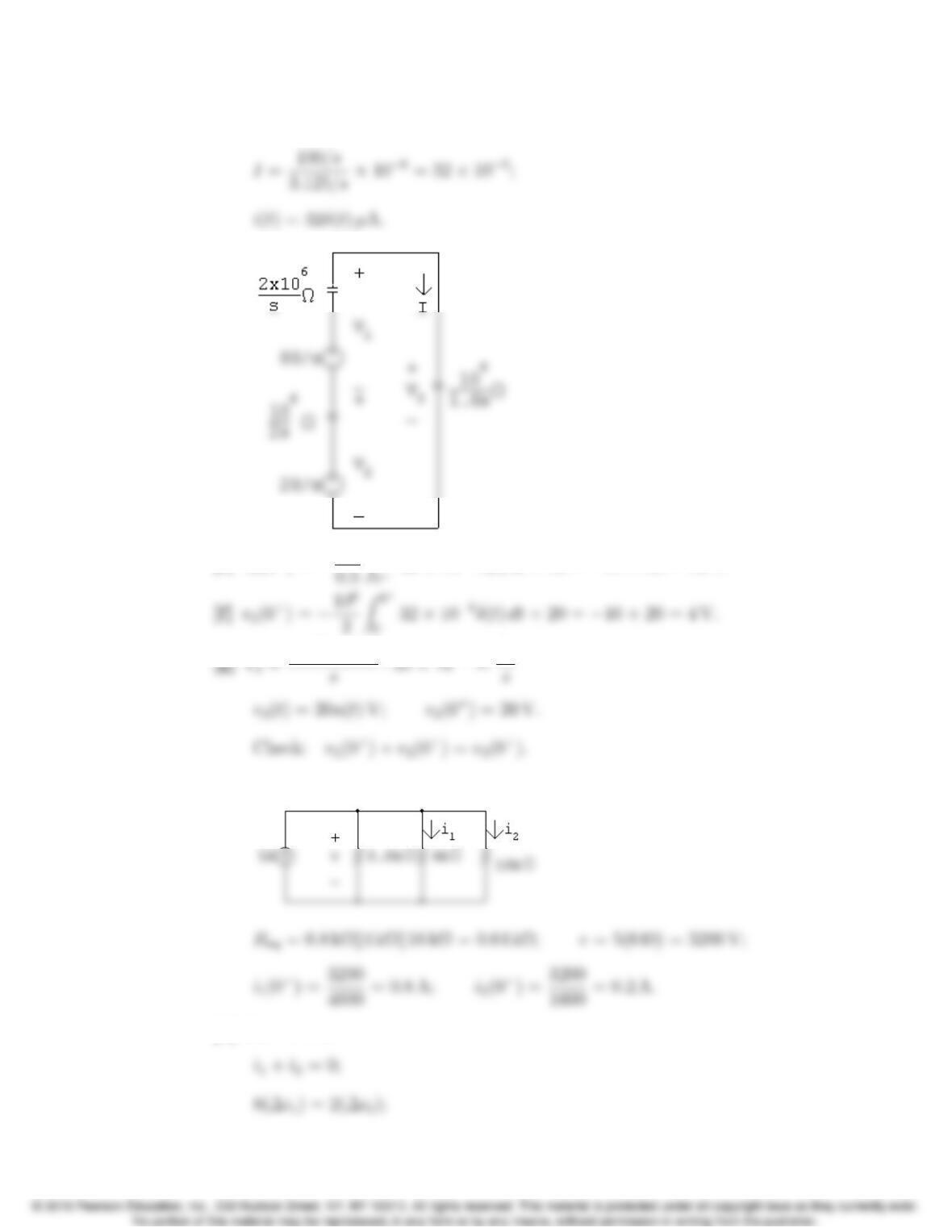
[c] V0=3
sI2=✓3
s◆40
3✓s
s2+4◆=40
s2+4 =K1
sj2+K⇤
1
s+j2.
Problems 13–89
[d] Let us begin by noting i1jumps from 0 to (80/3) A between 0and 0+
and in this same interval i2jumps from 0 to (40/3) A.Therefore in the
Thus our solutions for i1and i2are in agreement with known circuit
behavior.
Let us also note the impulsive voltage will impart energy into the circuit.
Since there is no resistance in the circuit, the energy will not dissipate.
Thus the fact that i1,i
2,and voexist for all time is consistent with
known circuit behavior.
13–90 CHAPTER 13. The Laplace Transform in Circuit Analysis
P 13.89 [a]
106
[b] At t= 0 the current in the 1 µF capacitor is 10δ(t)µA;
After the impulsive current has charged the 1 µF capacitor to 10 V it
Note – after the impulsive current passes the circuit becomes
P 13.90 [a] For t<0,0.5v1=2v2; therefore v1=4v2;
Problems 13–91
[d] For t>0:
[e] v1(0+)=106
32 ⇥106δ(t)dt +80=64 + 80 = 16 V.
P 13.91 [a] For t<0:
[b] For t>0: