CHAPTER 11
Exercises
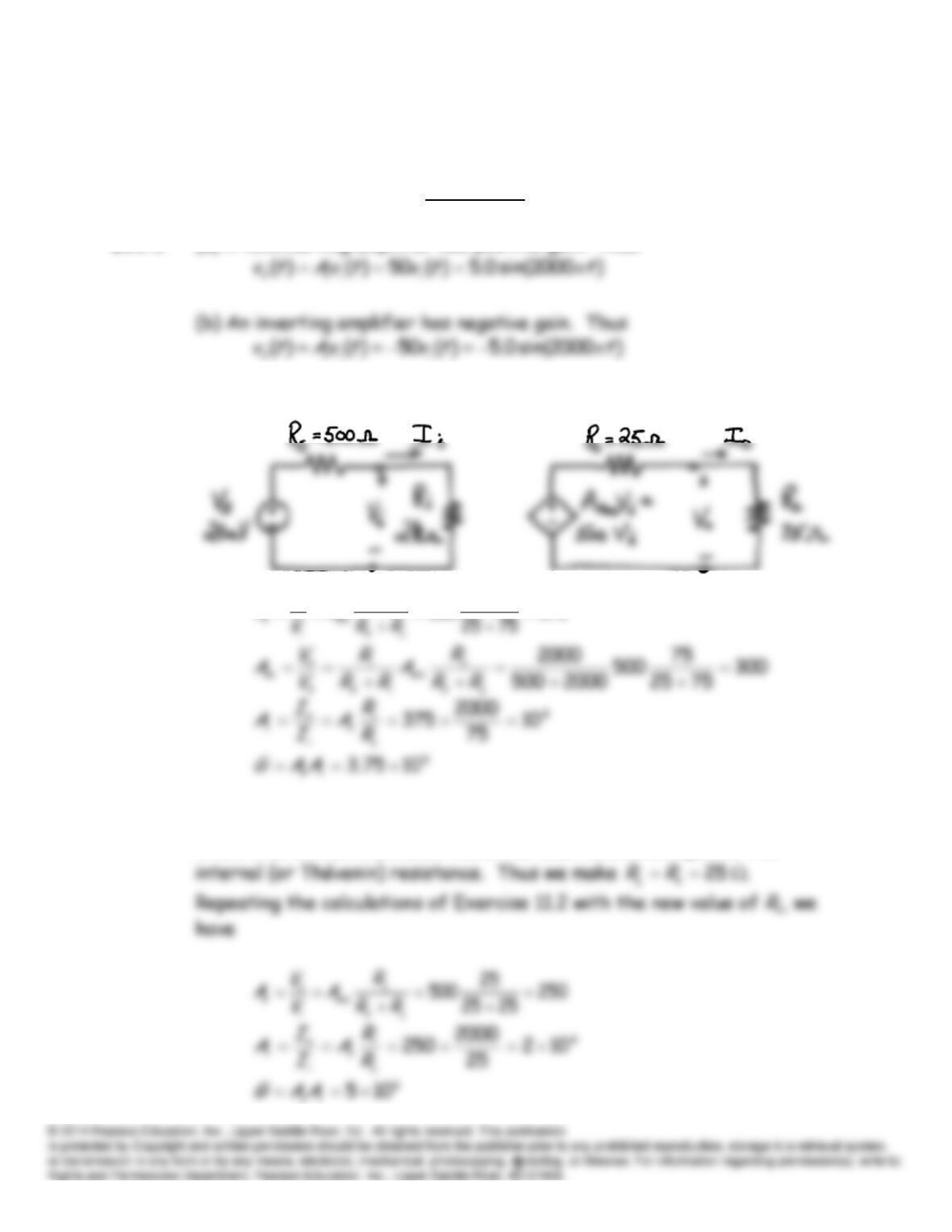
E11.1 (a) A noninverting amplifier has positive gain. Thus
E11.2
375
75
500
L
o
R
A
V
A
E11.3 Recall that to maximize the power delivered to a load from a source with
fixed internal resistance, we make the load resistance equal to the
250
25
500
L
o
R
A
V
A
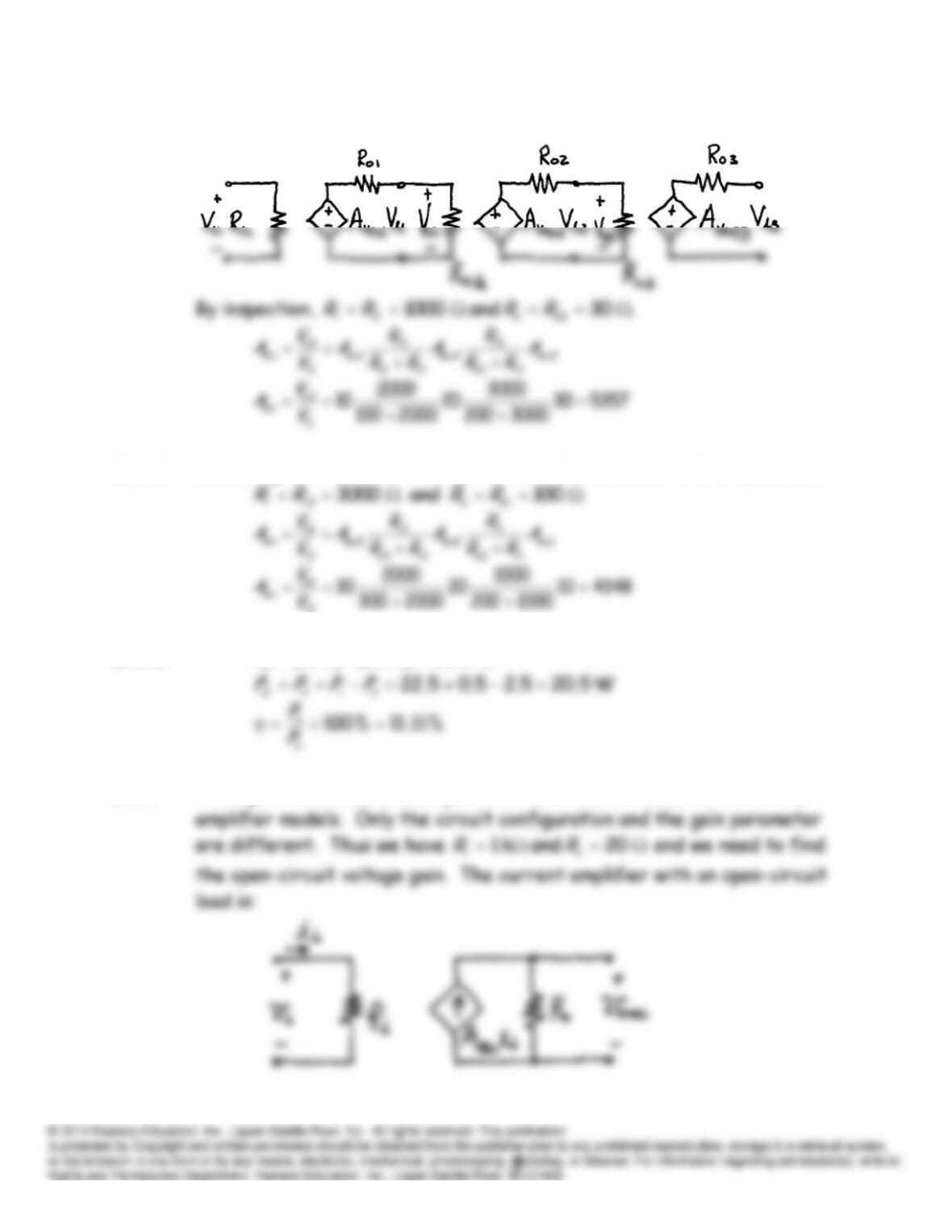
E11.4
E11.5 Switching the order of the amplifiers of Exercise 11.4 to 3-2-1, we have
E11.6
W 22.5A) (1.5V) 15(
P
E11.7 The input resistance and output resistance are the same for all of the
i
ii
i
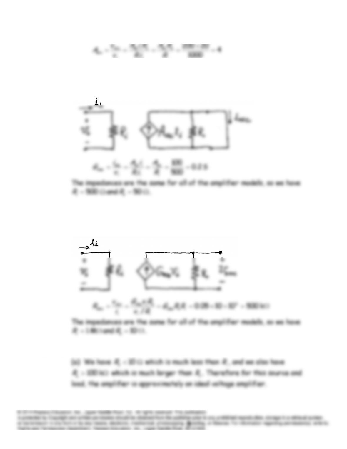
E11.8 For a transconductance-amplifier model, we need to find the short-
circuit transconductance gain. The current-amplifier model with a short-
circuit load is:
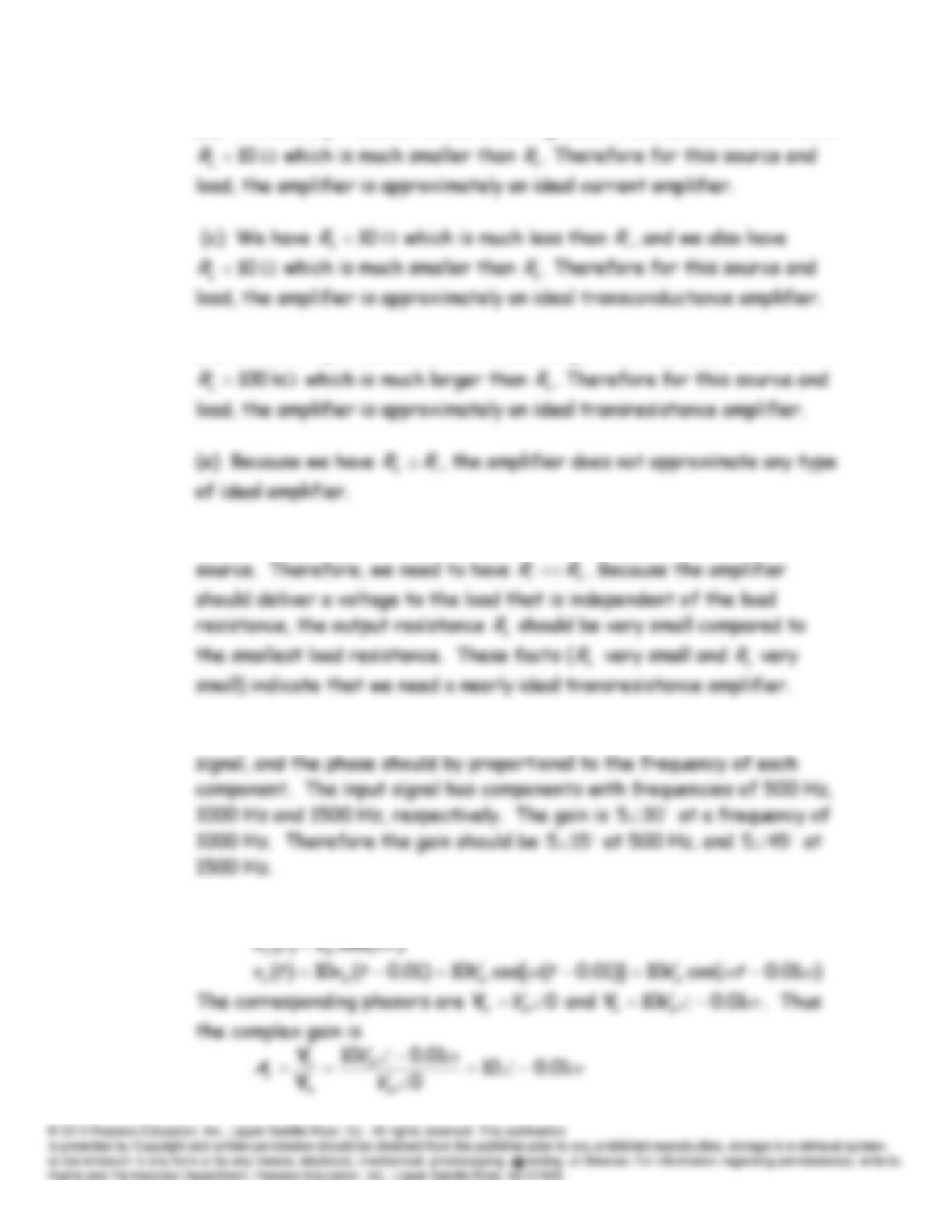
E11.9 For a transresistance-amplifier model, we need to find the open-circuit
transresistance gain. The transconductance-amplifier model with an
open-circuit load is:
E11.10 The amplifier has
. k 1 and k 1
o
iRR
(b) We have
k 100
s
R
which is much greater than
i
R
, and we also have
i
R
(d) We have
k 100
s
R
which is much larger than
i
R
, and we also have
k 100
E11.11 We want the amplifier to respond to the short-circuit current of the
E11.12 The gain magnitude should be constant for all components of the input
E11.13 We have
E11.15 Equation 11.13 states
E11.16 (a)
)()(100)( 2
tvtvtv ii
o
(b)
)()(100)( 2
tvtvtv ii
o
E11.17 With the input terminals tied together and a 1-V signal applied, the
E11.18 (a)
V 1
21
ii
id vvv
V 02/)( 21
cm
ii
ivvv
(b)
V 0
21
ii
id vvv
V 12/)( 21
cm
ii
ivvv
(c)
5.1002/)101100(2/)( 21
AAAd
E11.19 Except for numerical values this Exercise is the same as Example 11.13 in
the book. With equal resistances at the input terminals, the bias
The extreme contributions to the output voltage due to the offset
current are
E11.20 This Exercise is similar to Example 11.13 in the book with
1
s
R
= 50 kΩ and
2
s
R
= 0. With unequal resistances at the input terminals, the bias
The extreme contributions to the output due to the offset voltage are
The extreme contributions to the output voltage due to the offset
current are
Problems
P11.1 An inverting amplifier has negative voltage gain. The output waveform is
P11.3 Loading effects can occur either at the input or output of an amplifier.
The output voltage decreases when a load is connected because the
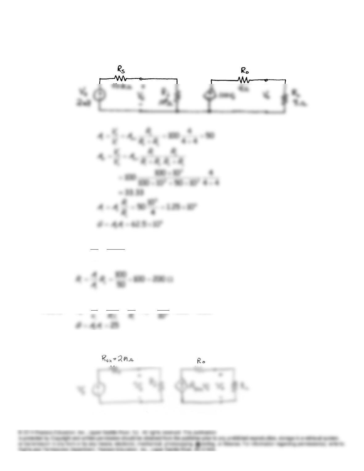
P11.4* The equivalent circuit is:
P11.5*
100
50
5000
v
iA
G
A
P11.6
05.0500
100
L
LL
o
R
iR
v
A
P11.7 The equivalent circuit is:
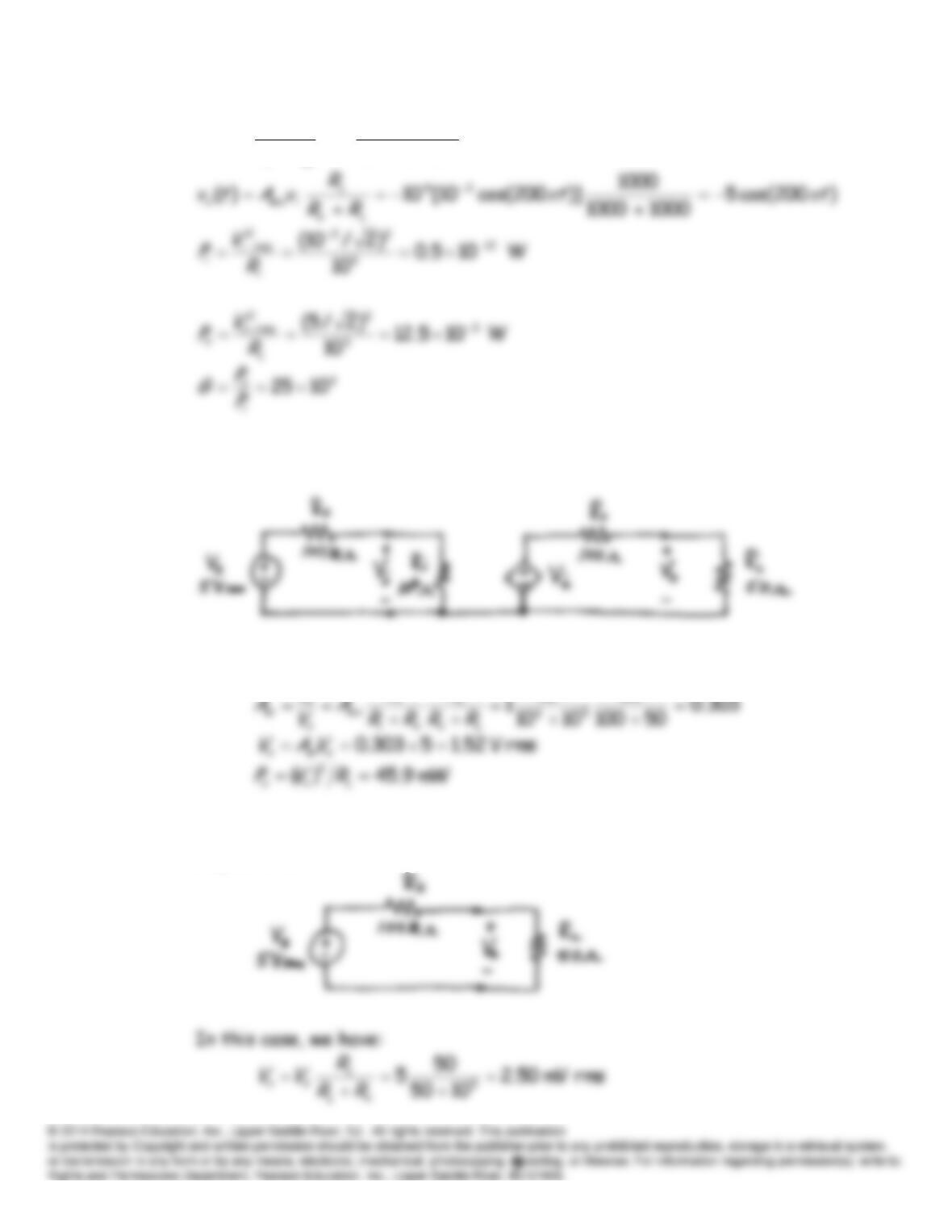
)200cos(10)]200cos(103[
10210
10
)( 33
66
6
ttv
RR
R
tv s
th
i
i
i
V
P11.8 The equivalent circuit using the amplifier is:
We have
50
10
6
R
R
V
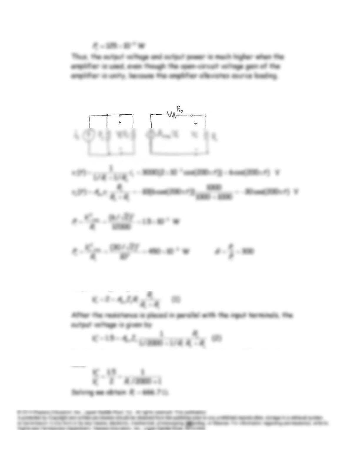
The equivalent for the load connected directly to the source without the
amplifier is:
P11.9 The equivalent circuit is:
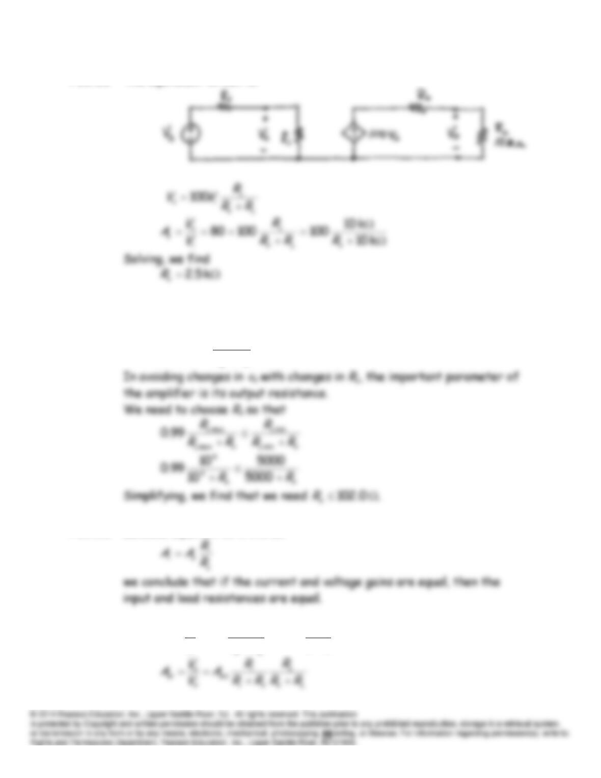
P11.10* Before the 2-k resistance is placed across the input terminals, the
output voltage is given by
Dividing the respective sides of Equation 2 by those of Equation 1, we
P11.11 The equivalent circuit is:
P11.12 We have
o
L
L
i
voco RR
R
vAv
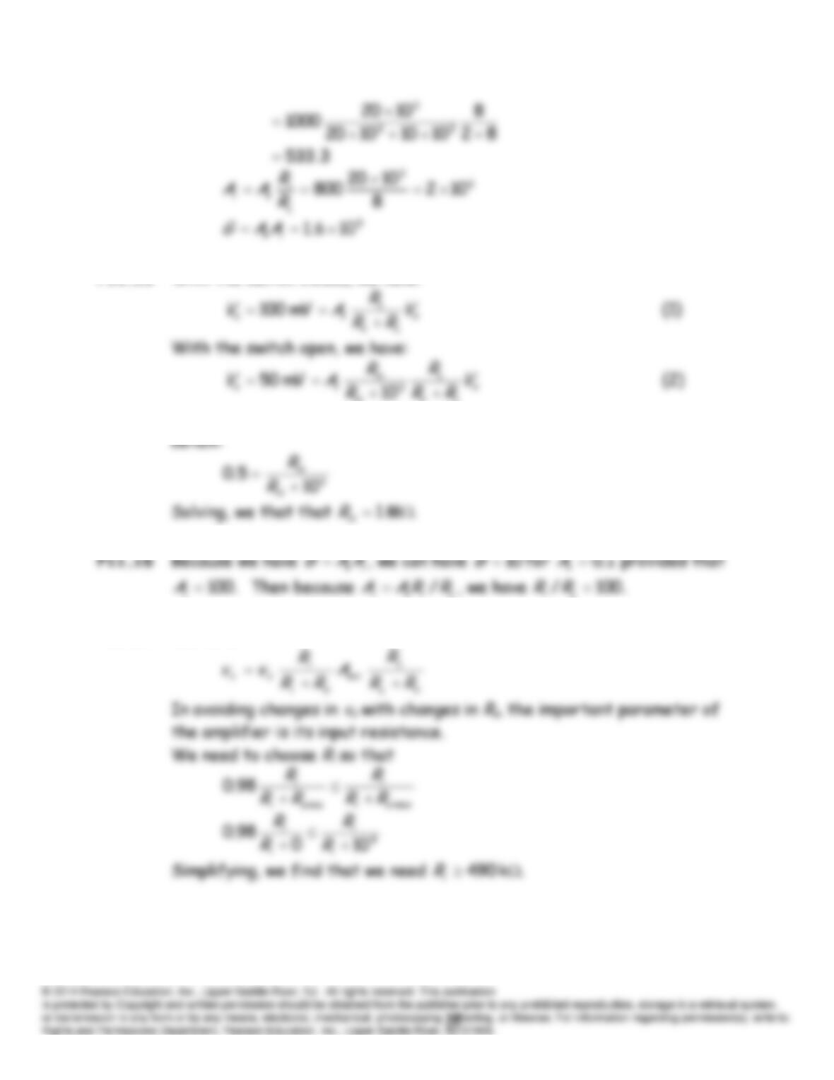
P11.13 Because Equation 11. 3 states
P11.14
800
82
8
1000
oc
L
o
L
v
i
o
vRR
R
A
V
V
A
P11.15* With the switch closed, we have:
L
o
in
Dividing the respective sides of Equation (2) by those of Equation (1), we
P11.17 We have
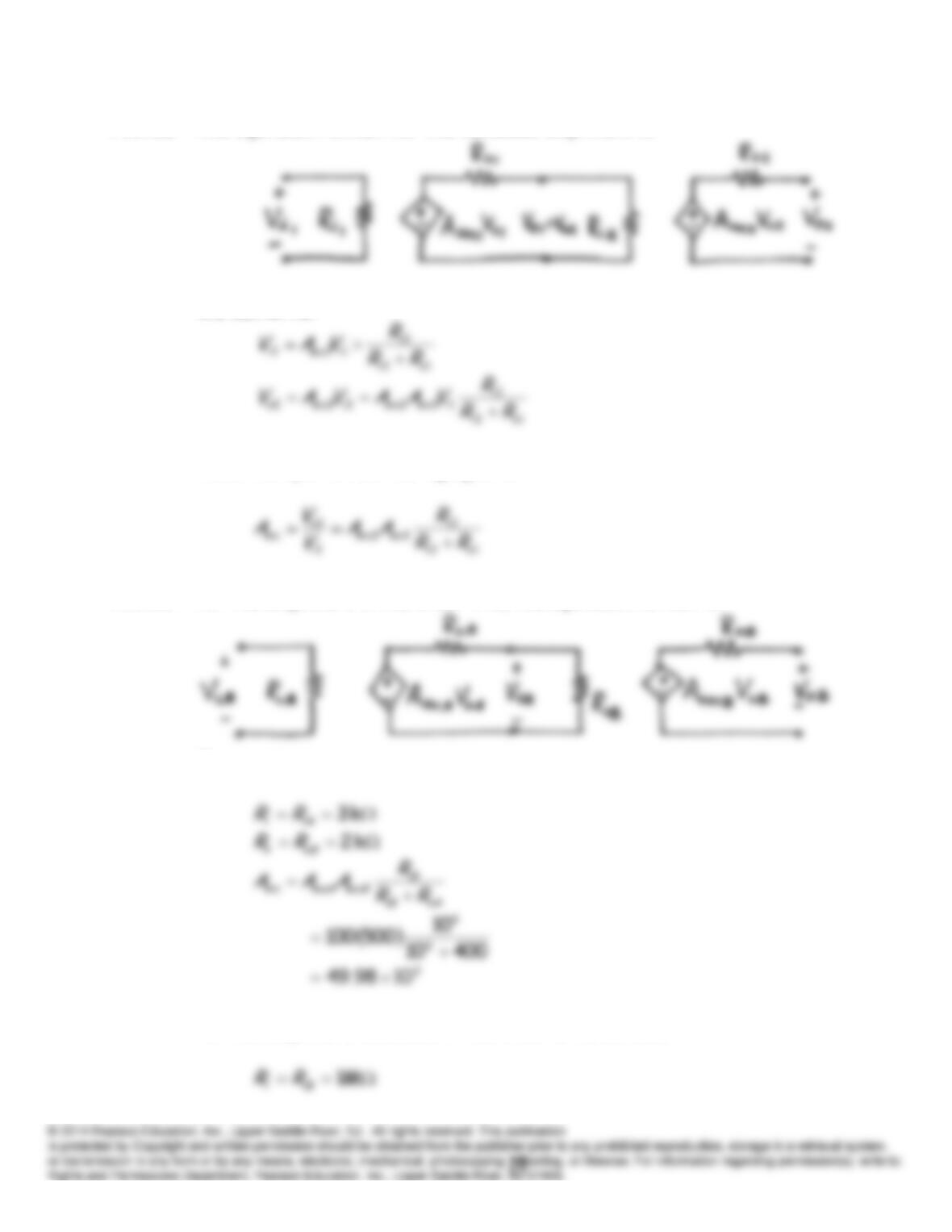
P11.18 The equivalent circuit for the cascaded amplifiers is:
We can write:
Thus, the open-circuit voltage gain is:
P11.19 For the amplifiers in the order
A
–
B
, the equivalent circuit is:
Thus, we have:
For the amplifiers cascaded in the order
B
–
A
, we have:
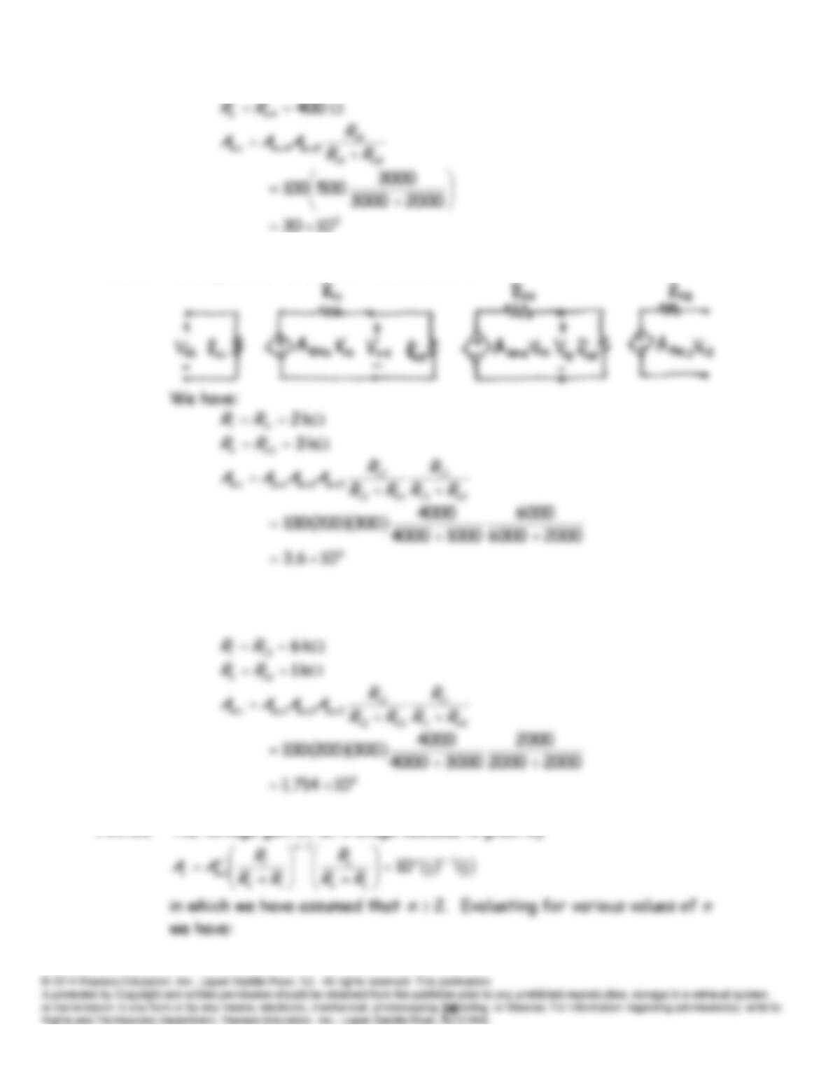
P11.20* The equivalent circuit for the cascade is:
P11.21 Reversing the order of the amplifiers of Problem P11.20, we have
P11.22* The voltage gain of an
n
-stage cascade is given by
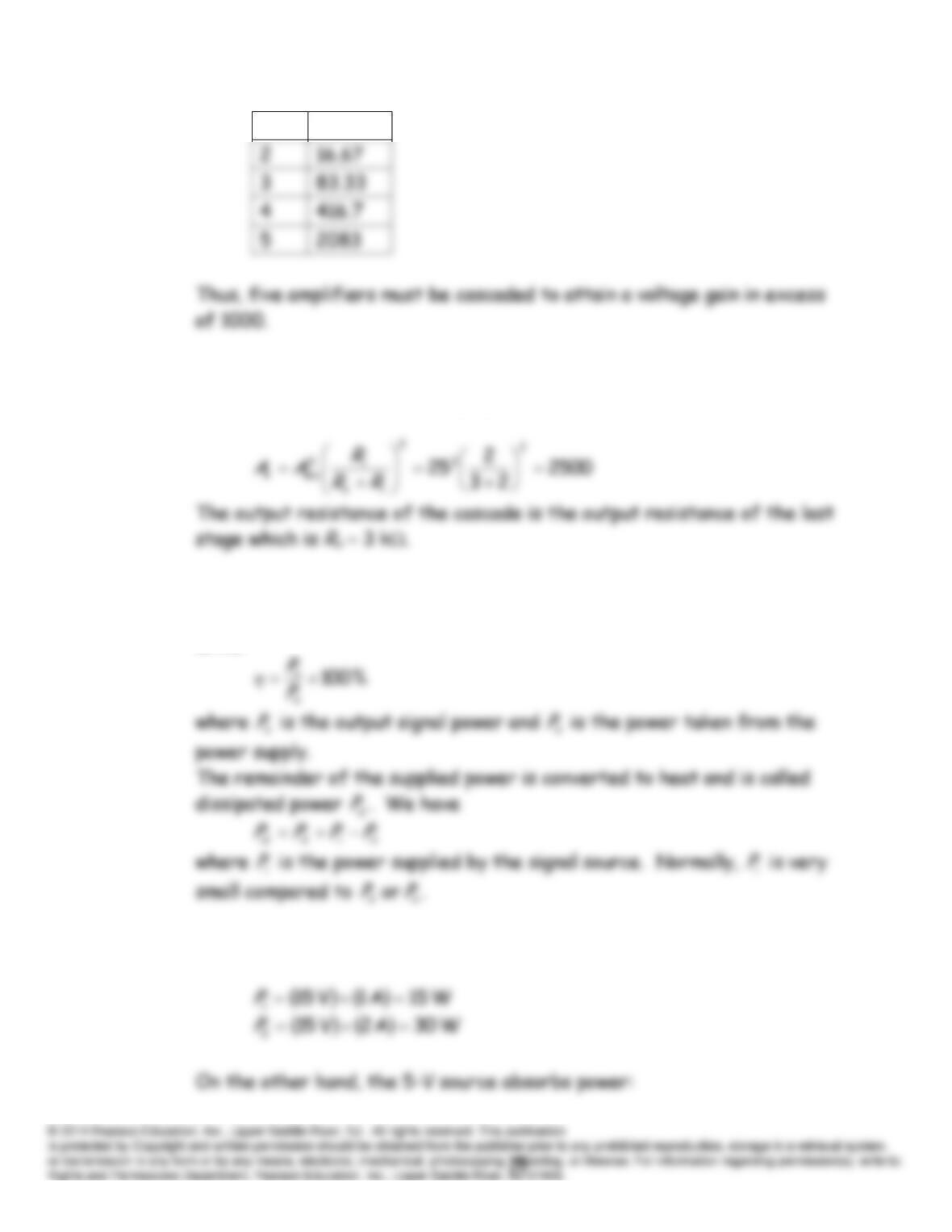
n
Av
P11.23 The input resistance of the cascade is that of the first stage which is
Ri
2 k. The open-circuit voltage gain is
P11.24 The power efficiency of an amplifier is the percentage of the power from
the dc power supply that is converted to output signal power. We can
write:
P11.25* The two 15-V sources deliver power:
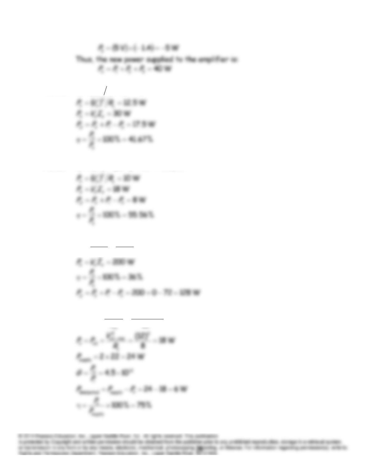
P11.26
W 10 7
2
iii RVP
P11.27
W 1.010)10(5262 μ
P11.28
W 72
8
)24(2
2
L
rmso
oR
V
P
P11.29
pW 4
10
)102(
6
23
2
1
1
rmsi
i
iR
V
PP
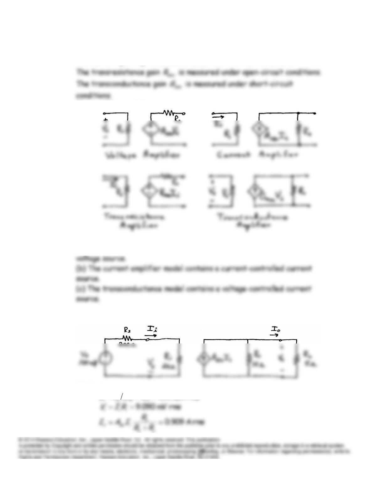
P11.30 The voltage gain
oc
v
A
is measured under open-circuit conditions.
The current gain
isc
A
is measured under short-circuit conditions.
The amplifier models are:
P11.31 (a) The transresistance amplifier model contains a current-controlled
P11.32* The equivalent circuit is:
We have:
rms A5.454 μ
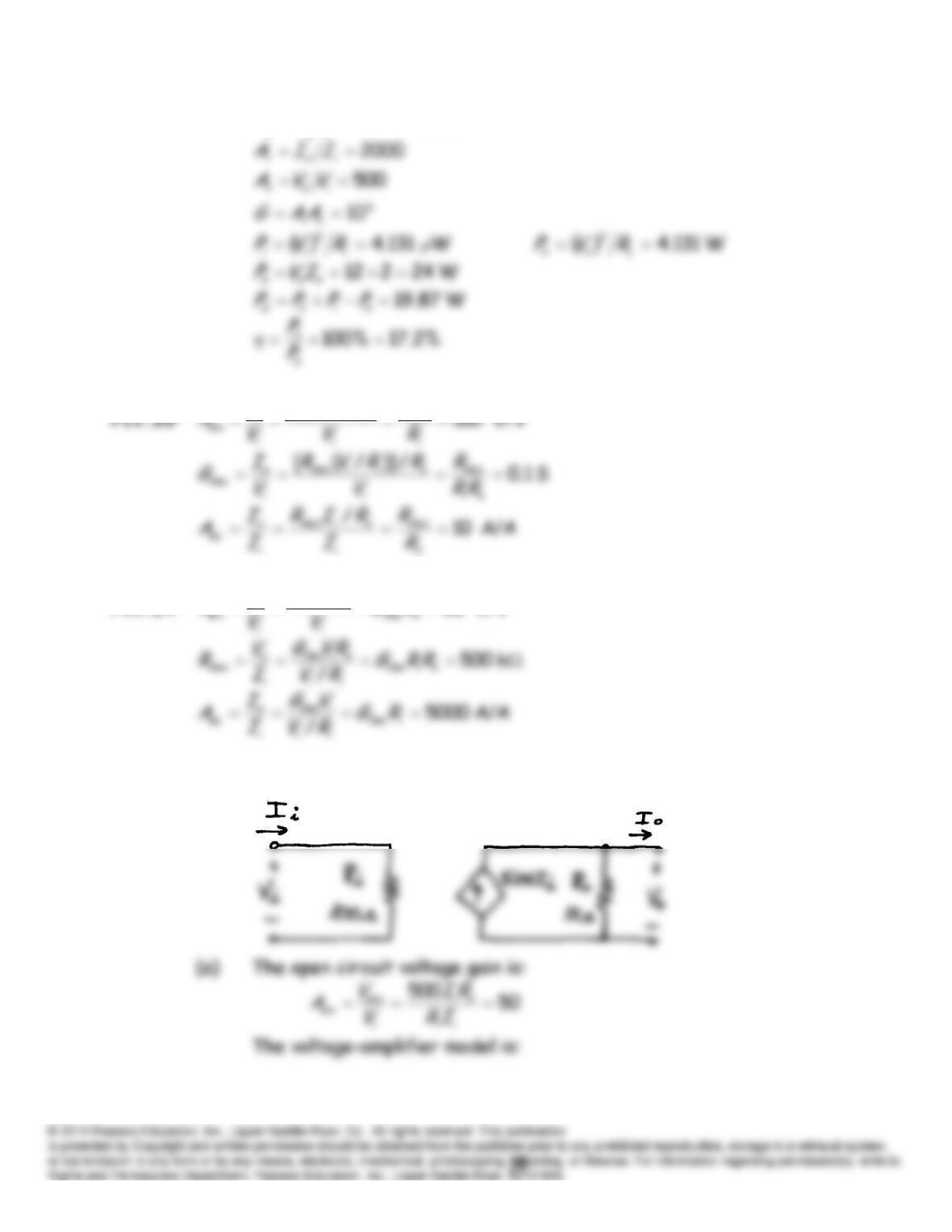
rmsV 554.4
o
L
oIRV
)/( ococ
m
ii
m
o
R
RVR
V
P11.34
V/V 50
sc
o
i
m
o
RVG
V
A
P11.35 We are given the parameters for the current amplifier model:
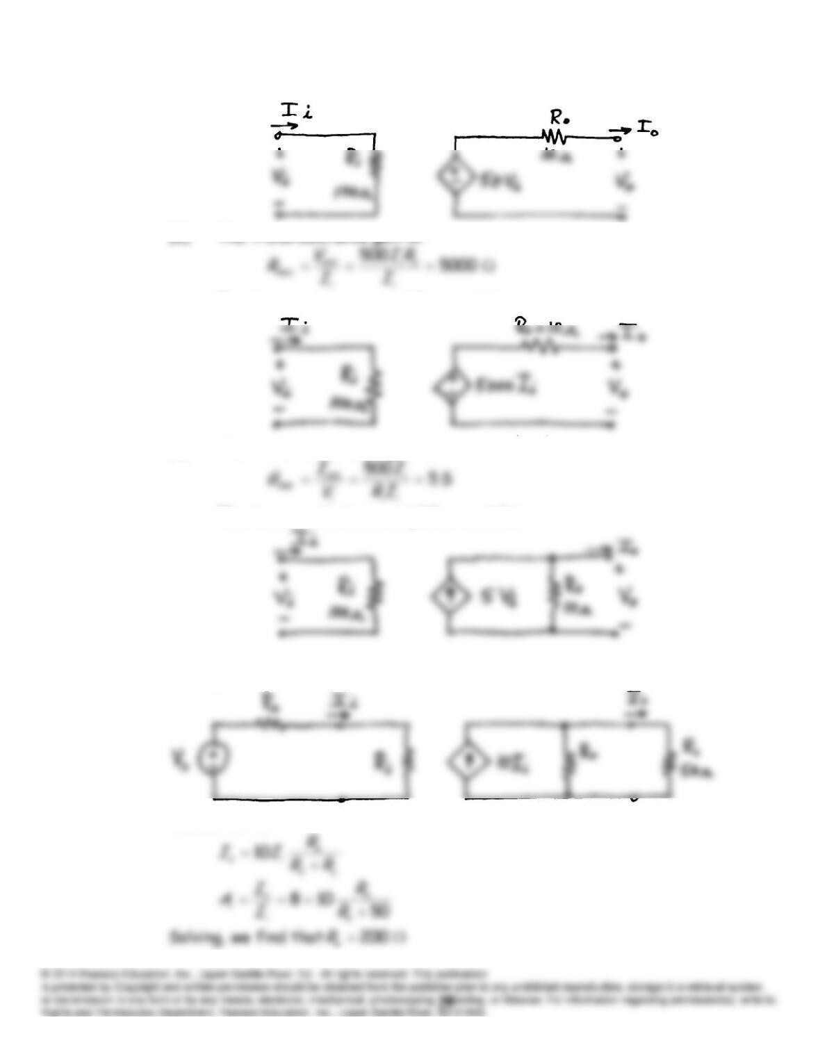
(b) The transresistance gain is:
The transresistance-amplifier model is:
(c) The transconductance gain is:
The transconductance-amplifier model is:
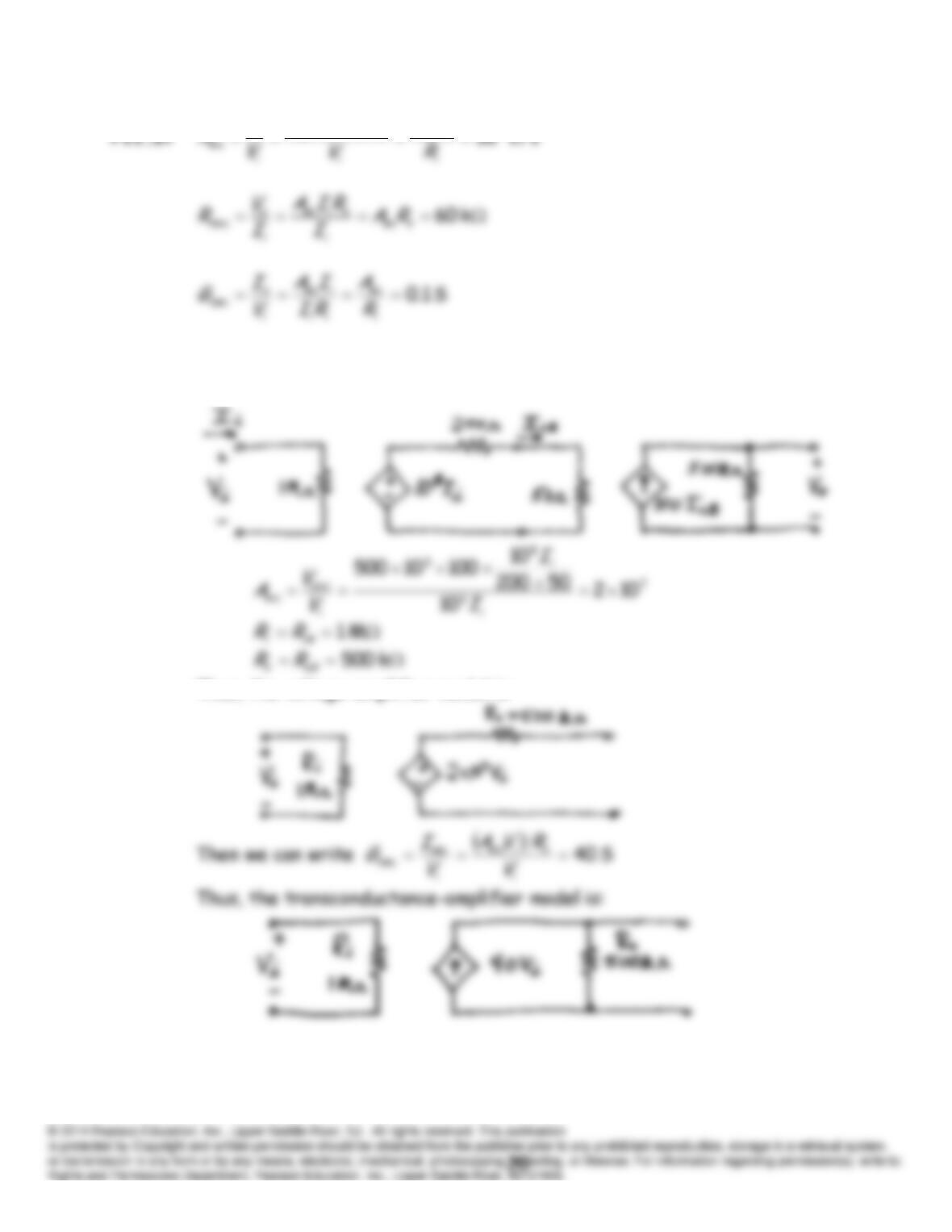
P11.36 The equivalent circuit is:
We can write:
)/( scsc
o
i
o
iii
o
RA
RRVA
V
P11.38* The equivalent circuit is:
Thus, the voltage-amplifier model is: