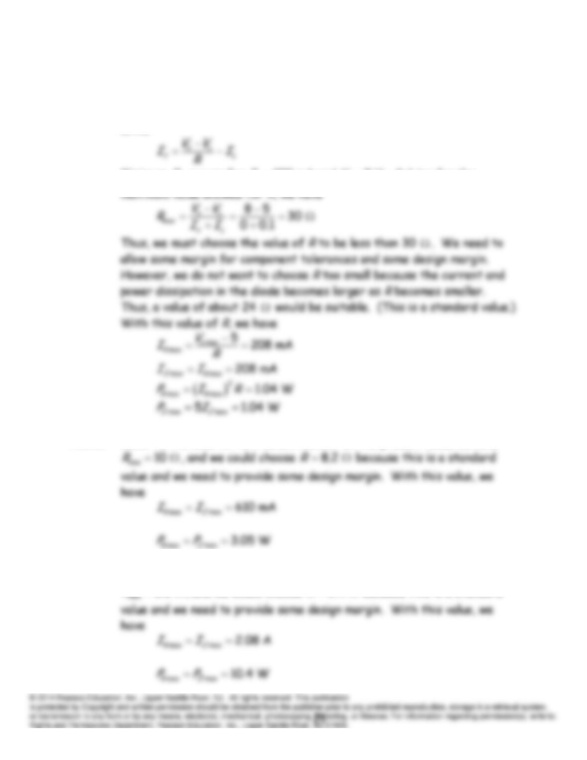
We must be careful to choose the value of
R
small enough so
z
I
remains
positive for all values of source voltage and load current. (Keep in mind
that the Zener diode cannot supply power.) From the circuit, we can
write
Minimum
z
I
occurs for
100 mA and 8 V
s
L
IV
. Solving for the
P10.27 Refer to the solution to Problem P10.26. In the present case, we have
8.2
R
P10.28 Refer to the solution to Problem P10.26. In the present case, we have
R
, and we would choose
2.4
R
because this is a standard
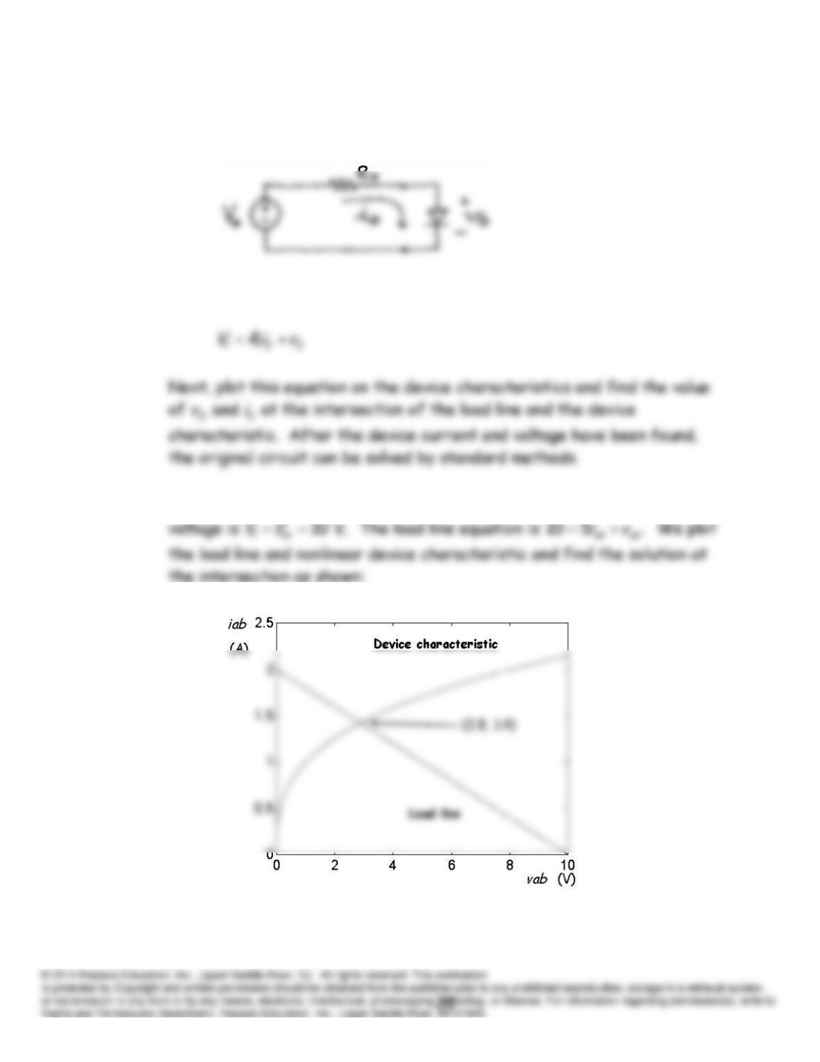
P10.29 First, find the Thévenin equivalent for the circuit as seen looking back
from the terminals of the nonlinear device:
Then, write the KVL equation for the equivalent circuit:
P10.30* The Thévenin resistance is
/ 10/2 5 .
t oc sc
R V I
Also the Thévenin
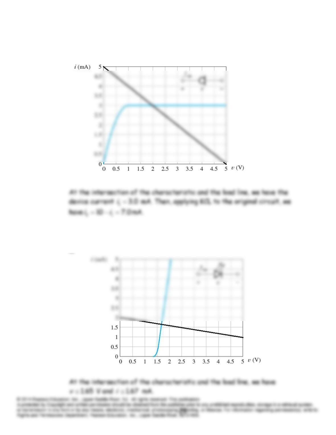
P10.31 If we remove the diode, the Thévenin equivalent for the remaining circuit
consists of a 5-V source in series with a 1-k resistance. The load line is
P10.32 If we remove the diode, the Thévenin equivalent for the remaining circuit
consists of a 10-V source in series with a 5-k resistance. The load line
is
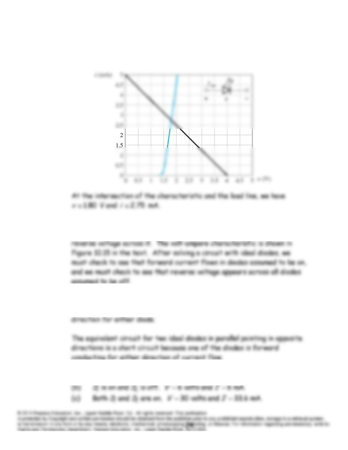
P10.33 If we remove the diode, the Thévenin equivalent for the remaining circuit
consists of a 4-V source in series with an 800- resistance. The load line
is
P10.34 An ideal diode acts as a short circuit as long as current flows in the
forward direction. It acts as an open circuit provided that there is
P10.35 The equivalent circuit for two ideal diodes in series pointing in opposite
directions is an open circuit because current cannot flow in the reverse
P10.36* (a)
12
is on and is off. 10 volts and 0.
D D V I
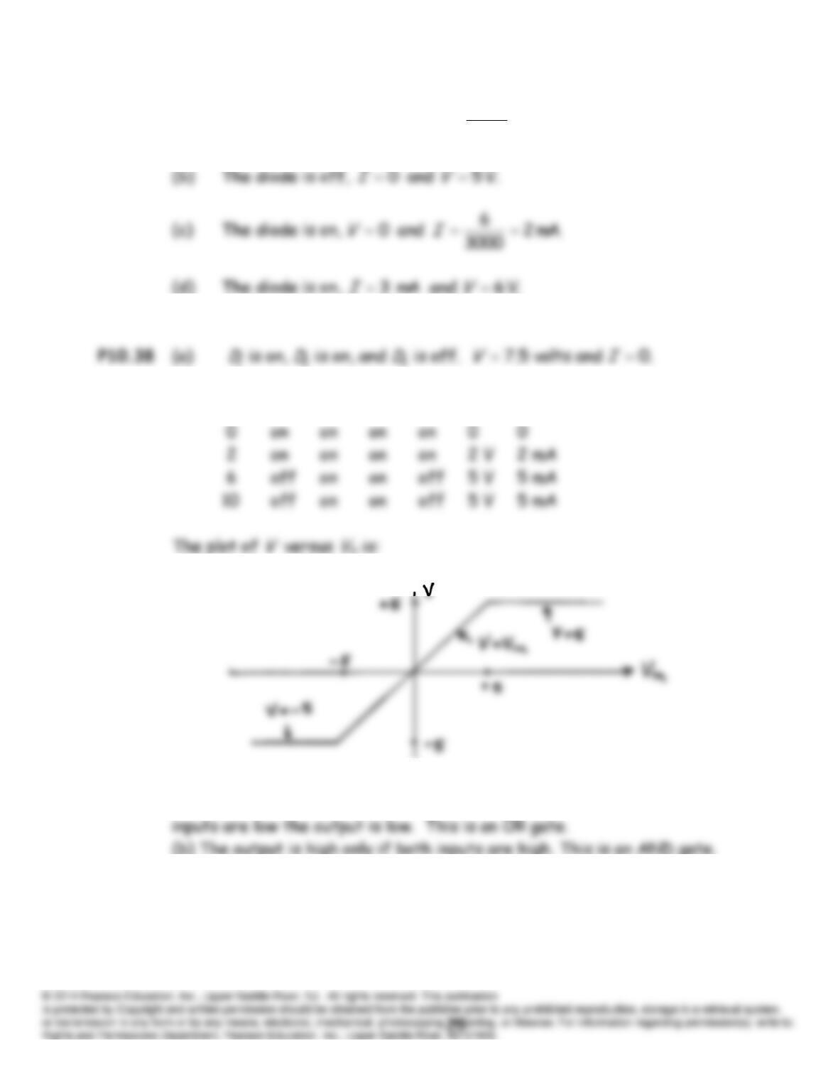
P10.37 (a) The diode is on,
mA. 2
5000
10
and 0
IV
(b)
in
V
1
D
2
D
3
D
4
D
V
I
P10.39 (a) The output is high if either or both of the inputs are high. If both
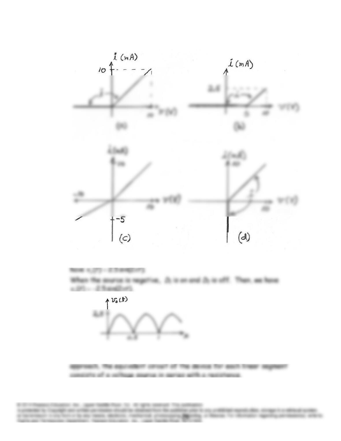
P10.40
P10.41 When the sinusoidal source is positive,
D
2 is on and
D
1 is off. Then, we
P10.42 If a nonlinear two-terminal device is modeled by the piecewise-linear
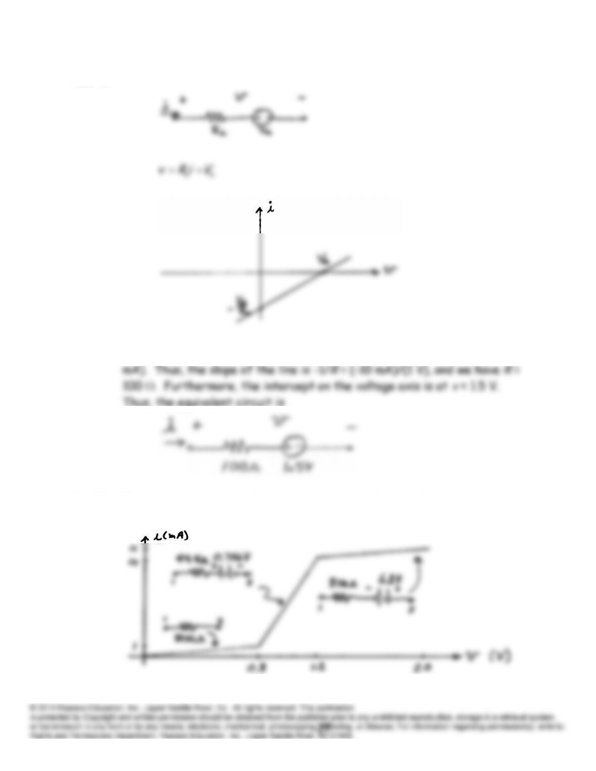
P10.43
P10.44 We know that the line passes through the points (2 V, 5 mA) and (3 V, 15
10.45* The equivalent circuits for each segment are shown below:
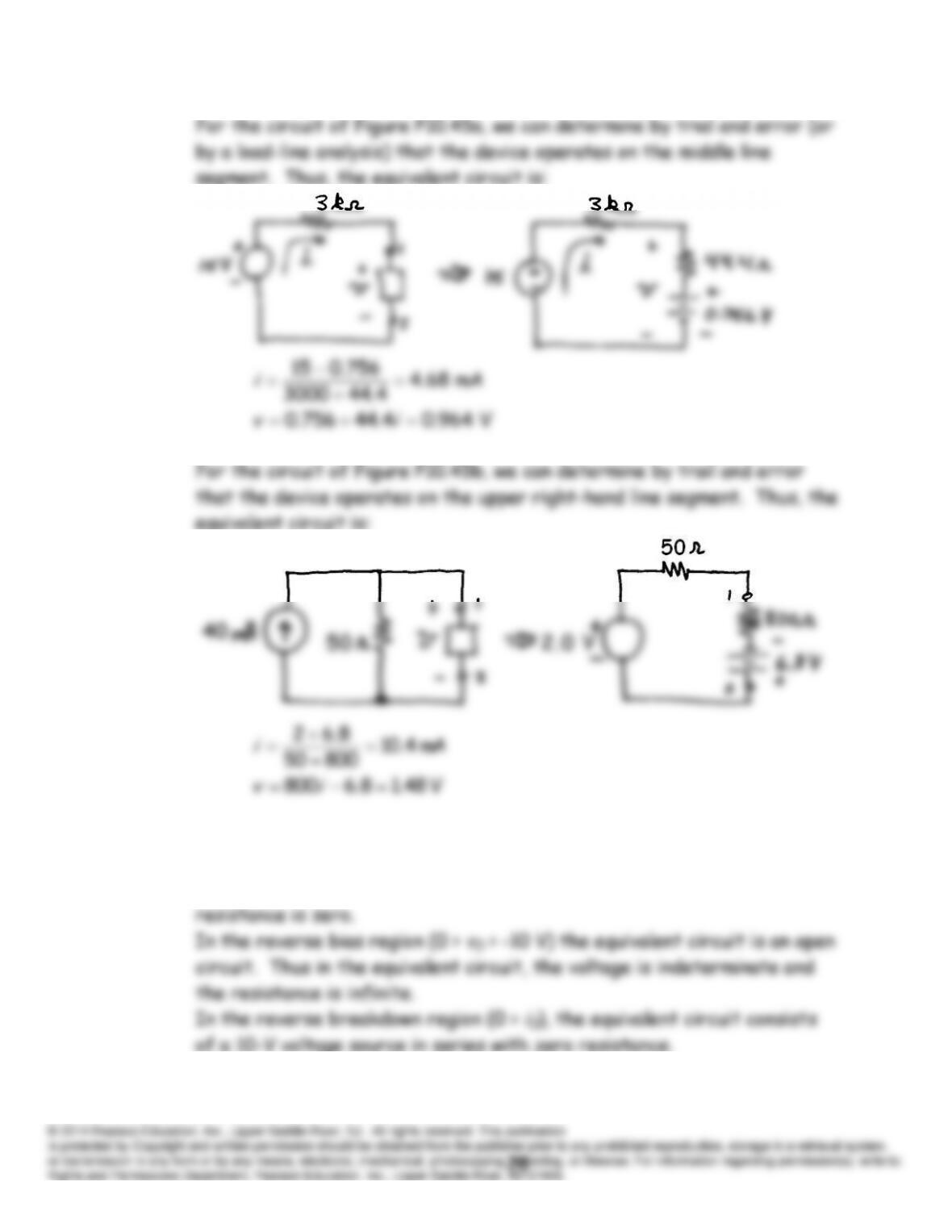
P10.46 In the forward bias region (
iD
> 0), the equivalent circuit is a short
circuit. Thus in the equivalent circuit, the voltage source is zero and the
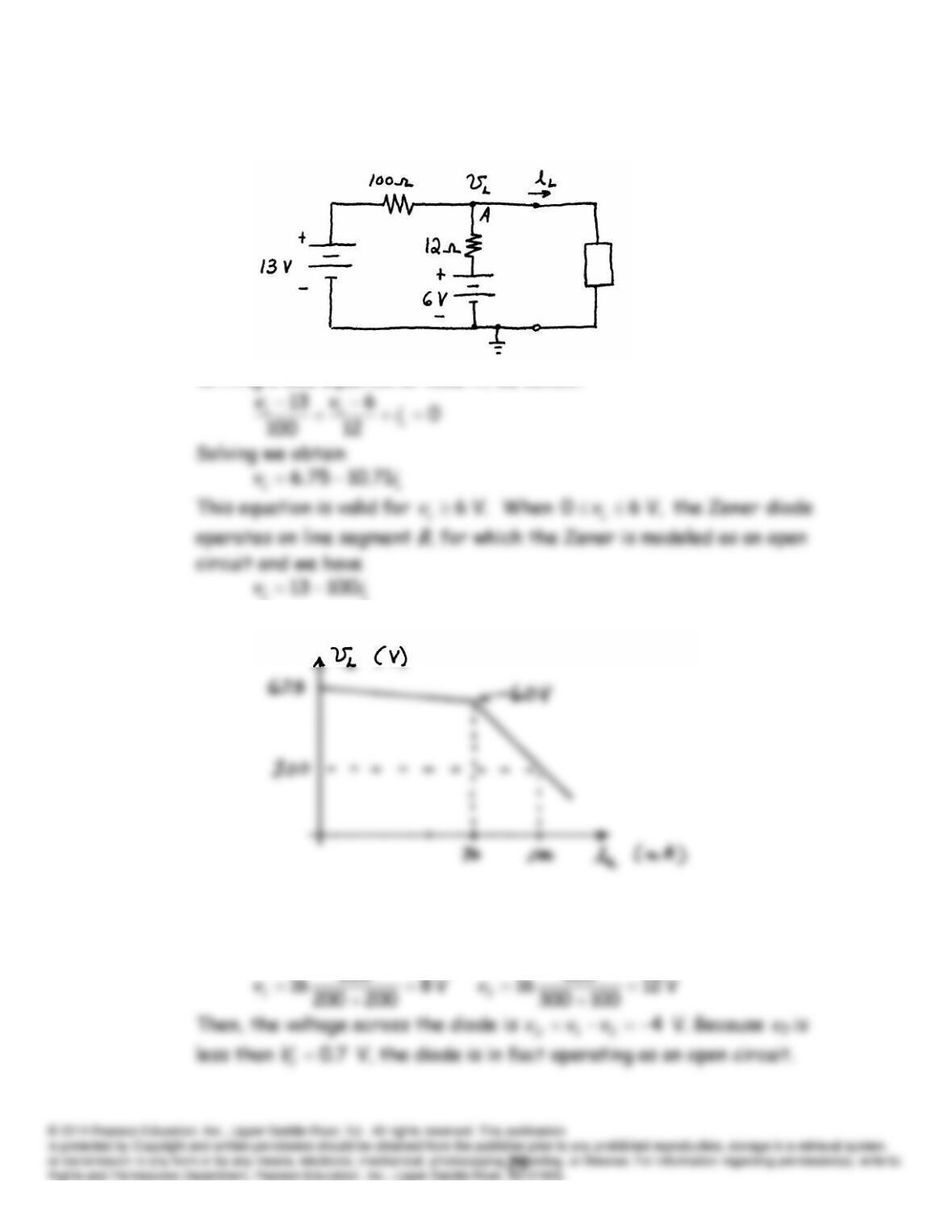
P10.47* For small values of
iL
, the Zener diode is operating on line segment
C
of
Figure 10.19, and the equivalent circuit is
Writing a KCL equation at node A, we obtain:
Plotting these equations results in
P10.48 (a) Assuming that the diode is an open circuit, we can compute the node
voltages using the voltage-division principle.
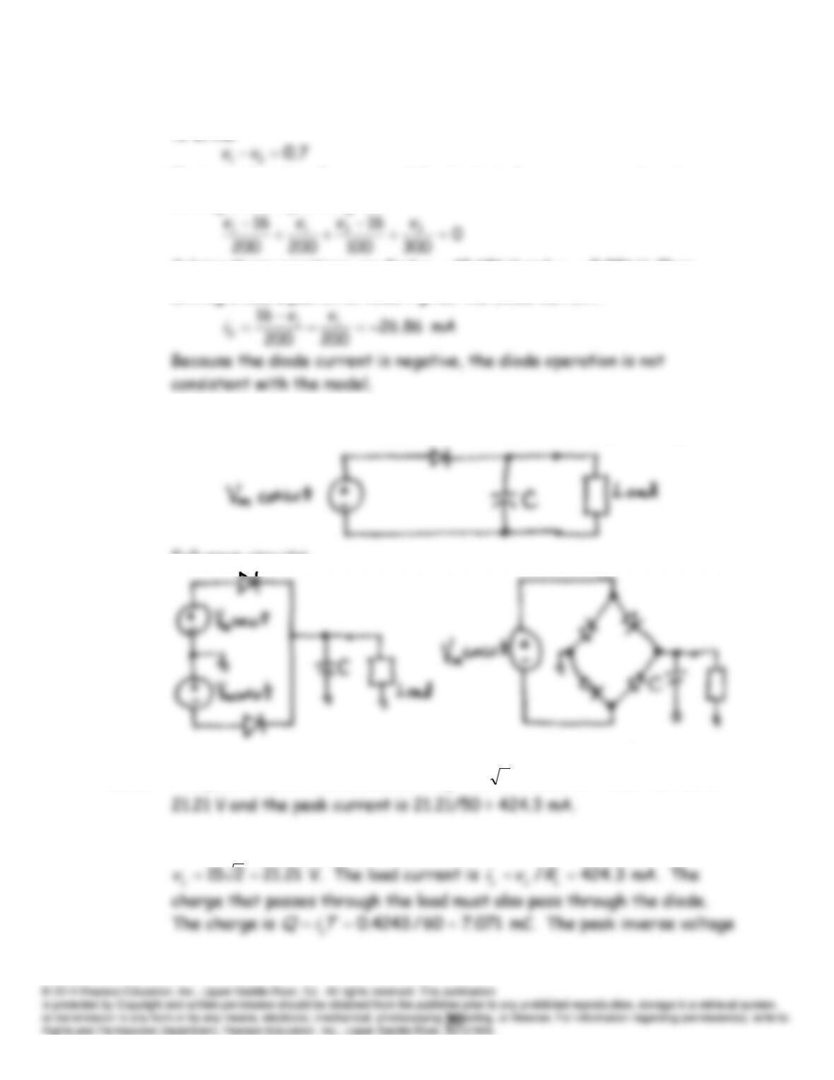
(b) Assuming that the diode operates as a voltage source, we can use KVL
to write:
Placing a closed surface around the diode to form a super node and
writing a KCL equation gives
Solving these equations, we find
686.10
1
v
V and
986.9
2
v
V. Then,
writing a KCL equation at node 1 gives the diode current.
P10.49 Half-wave rectifier with a capacitance to smooth the output voltage:
Full-wave circuits:
P10.50 The peak value of the ac source is
21.21215
m
V
V. Thus the PIV is
P10.51 The dc output voltage is equal to the peak value of the ac source, which is
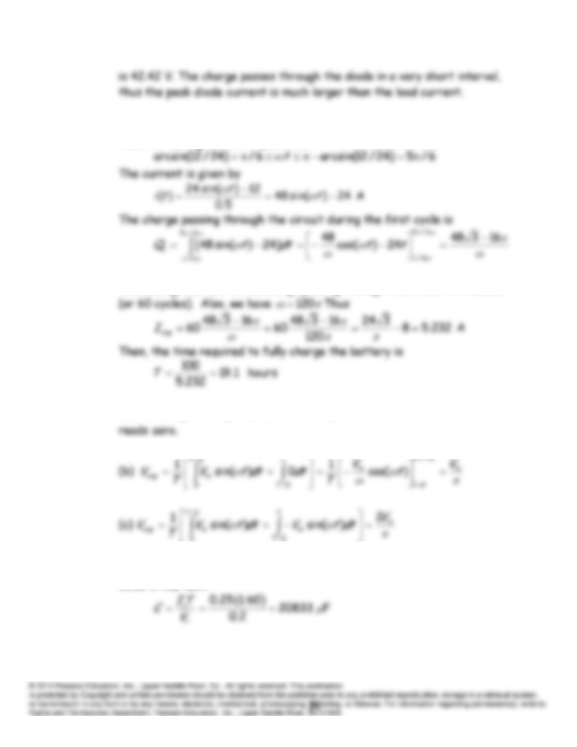
P10.52 The diode is on for
)sin(
tVV m
B
. Substituting values and solving, we
find that during the first cycle after
t
= 0 the diode is on for
The average current is the charge passing through the circuit in 1 second
P10.53 (a) The integral of
)sin(
tVm
over one cycle is zero, so the dc voltmeter
P10.54* For a half-wave rectifier, the capacitance required is given by Equation
10.10 in the text.
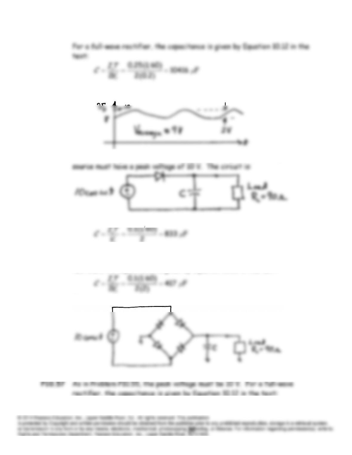
P10.55* The output voltage waveform is:
The peak voltage is approximately 10 V. Assuming an ideal diode, the ac
The capacitance required is given by Equation 10.10 in the text.
r
P10.56 As in Problem P10.55, the peak voltage must be 10 V. For a full-wave
rectifier, the capacitance is given by Equation 10.12 in the text:
The circuit diagram is:
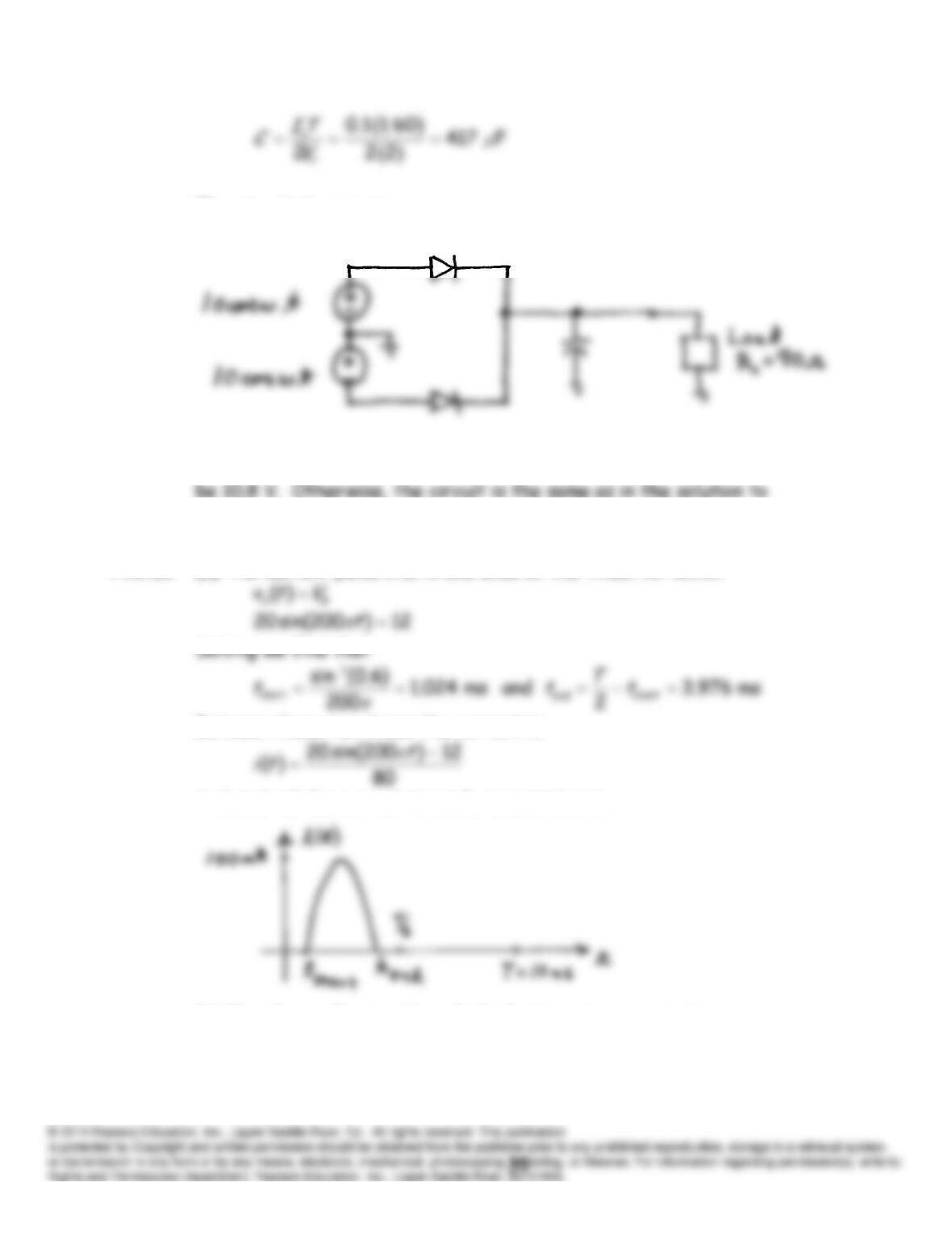
The circuit diagram is:
P10.58 If we allow for a forward diode drop of 0.8 V, the peak ac voltage must
Problem P10.55.
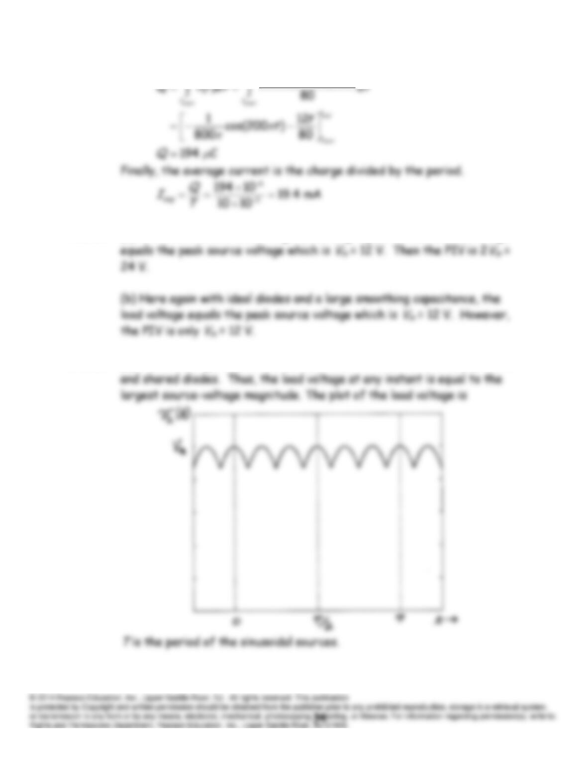
P10.59 (a) The current pulse starts and ends at the times for which
Between these two times the current is
A sketch of the current to scale versus time is
(b) The charge flowing through the battery in one period is
20 sin(200 ) 12
end end
tt
t
P10.60 (a) With ideal diodes and a large smoothing capacitance, the load voltage
P10.61 (a) The circuit operates as three full-wave rectifiers with a common load
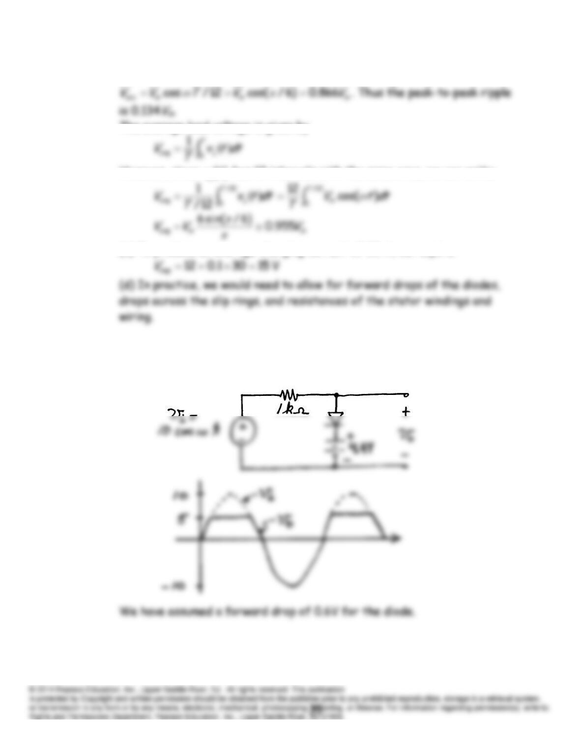
(b) The minimum voltage occurs at
12/
Tt
and is given by
The average load voltage is given by
However, since
)(
tv L
has 12 intervals with the same area, we can write:
(c) To produce an average charging current of 30 A, we require
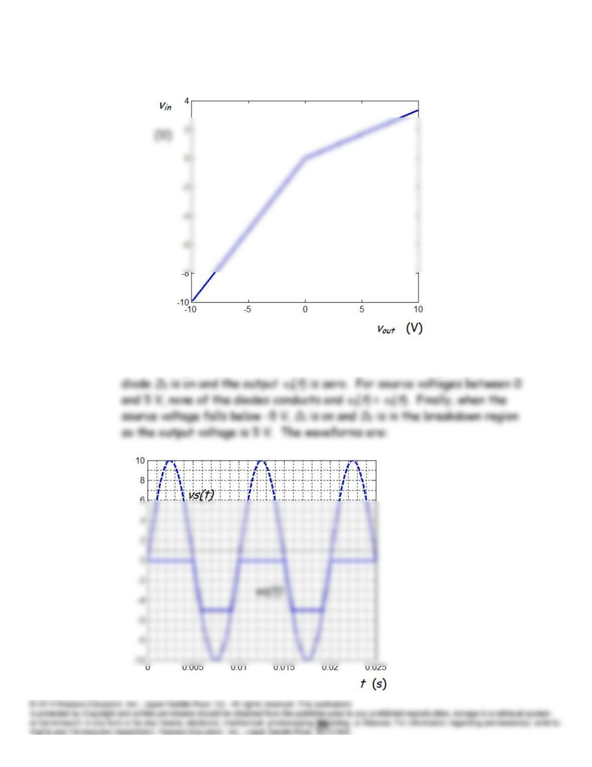
P10.62 A clipper circuit removes or clips part of the input waveform. An
example circuit with waveforms is:
P10.63
P10.64 Refer to Figure P10.64 in the book. When the source voltage is positive,