316
CHAPTER 12
SHAFT DESIGN
GENERAL NOTES CONCERNING SOLUTIONS TO SHAFT DESIGN PROBLEMS
Shafts with Only Radial Loads Applied to Them:
Torques and Forces Acting Radial to Shaft Comprehensive
Figure P12 1:
Figure P12 2:
Shafts with both Radial and Axial Loads Applied to Them:
Torques and Forces Acting Radial and Axial to Shaft Comprehensive
Other Comprehensive Design Problems
318
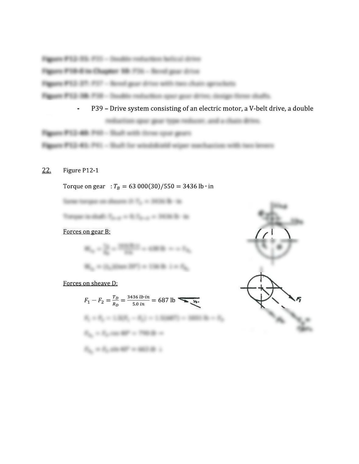
Figure P12 39:
B
319
A
320
A
C
D
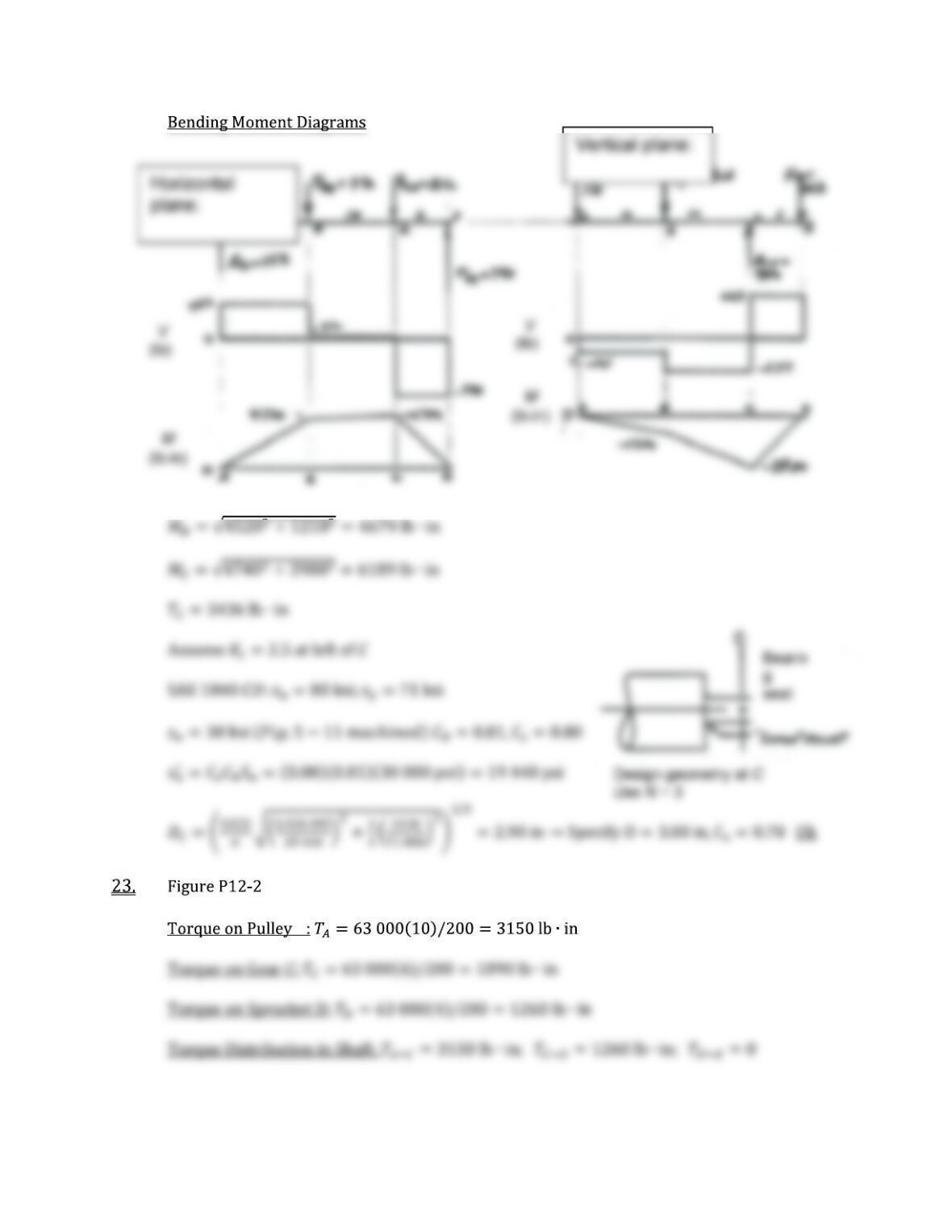
Horizontal
plane:
Vertical
plane:
321
24. Figure P12-3
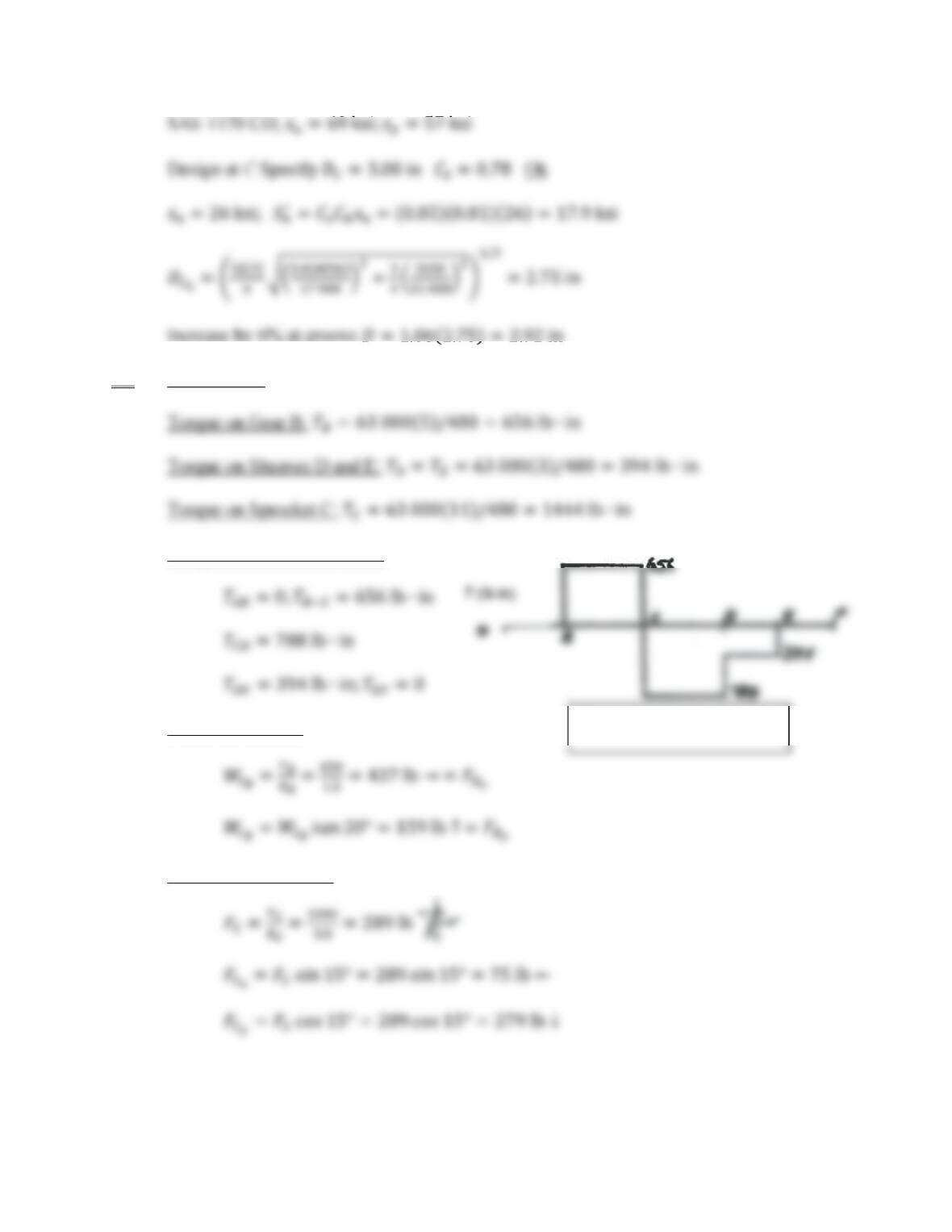
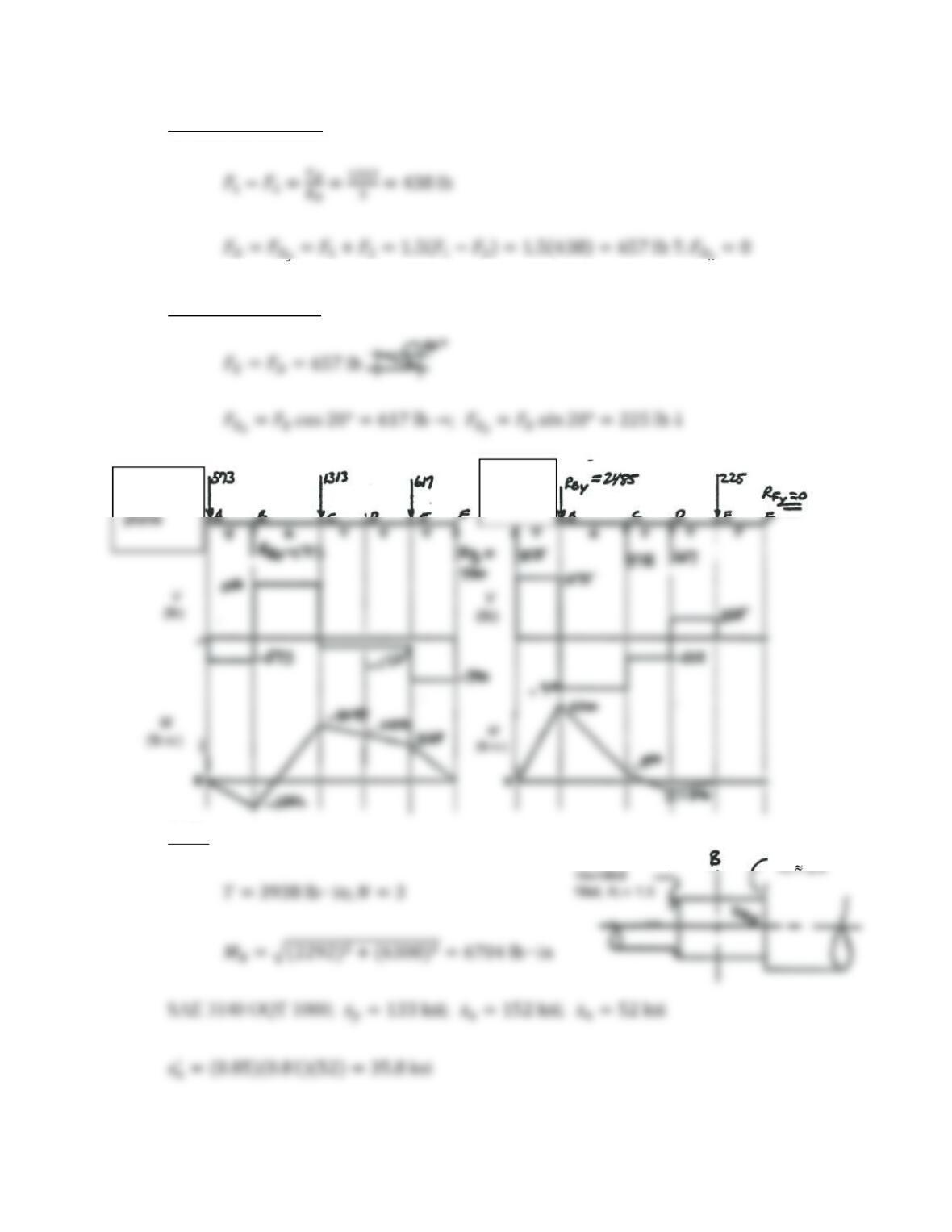
Torque Distribution in Shaft:
Forces on Gear B:
Forces on Sprocket C:
Torque diagram for shaft
322
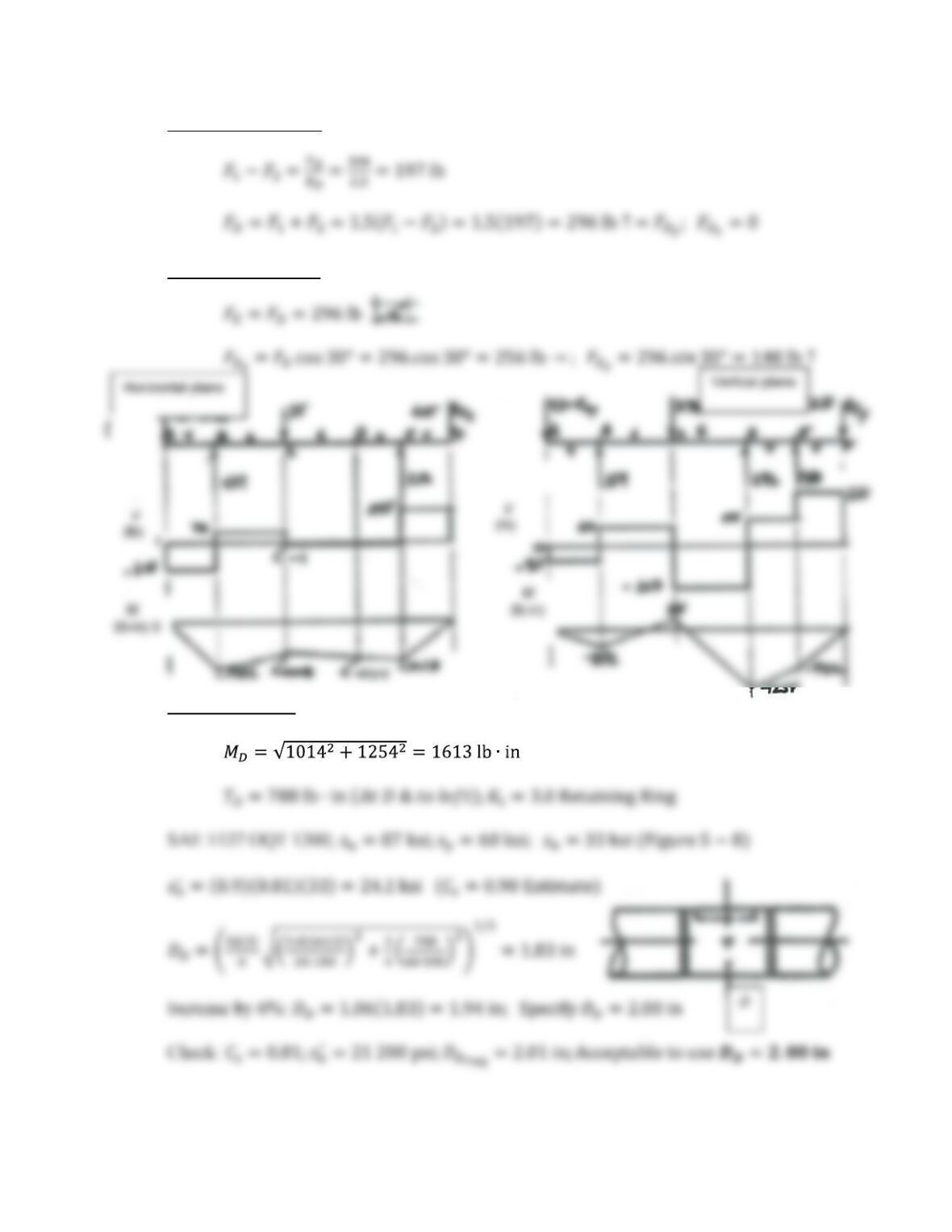
Forces on Sheave D:
Forces on Sheave E:
Worst Case at D:
323
25. Figure P12-4
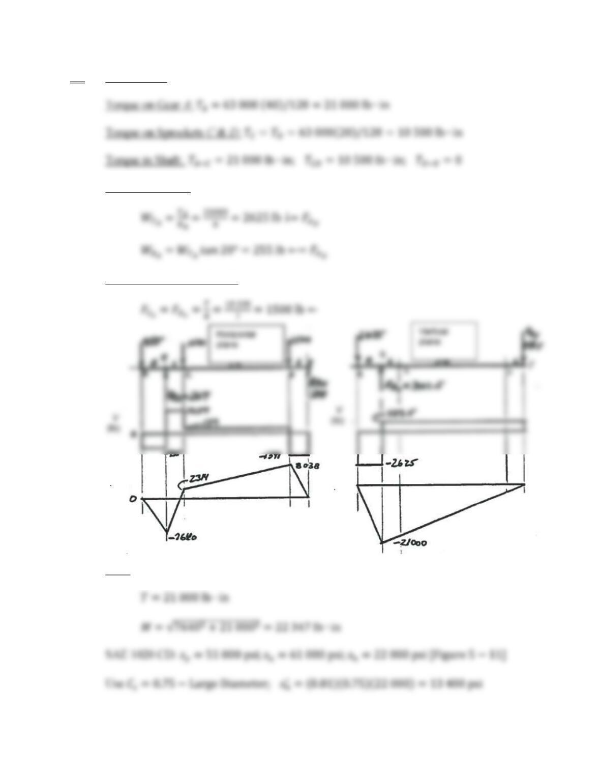
Forces on Gear A:
Forces on Sprockets C & D:
At B:
M
(lb in) M
(lb in)
324
To the right of B:
To the left of B:
26. Figure P12-5
Forces on Sheave A:
Forces on Gear D:
Bearing
seat
D
DBR
Small radius, Kt
2 5
DBL
325
Forces on Sprocket E:
At C:
C Kt 1.5
326
27. Figure P12-6
Torque on Sheave A and Gear E:
Forces on Sheave A:
Forces on Gear E:
327
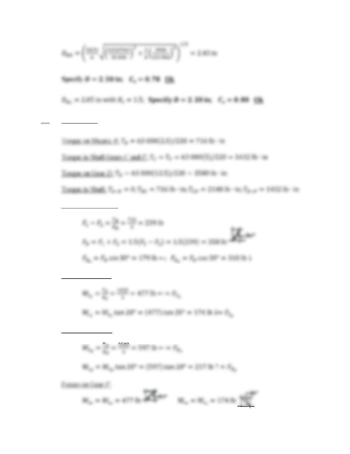
28. Torque on Gear A:
Figure P12-7
Forces on Gear A:
Forces on Gear C:
T
(lb in)
328
Forces on Sheave D:
Forces on Sheave E:
At B:
Horizonta
l
Vertical
plane
Sharp fillet
Well-
329
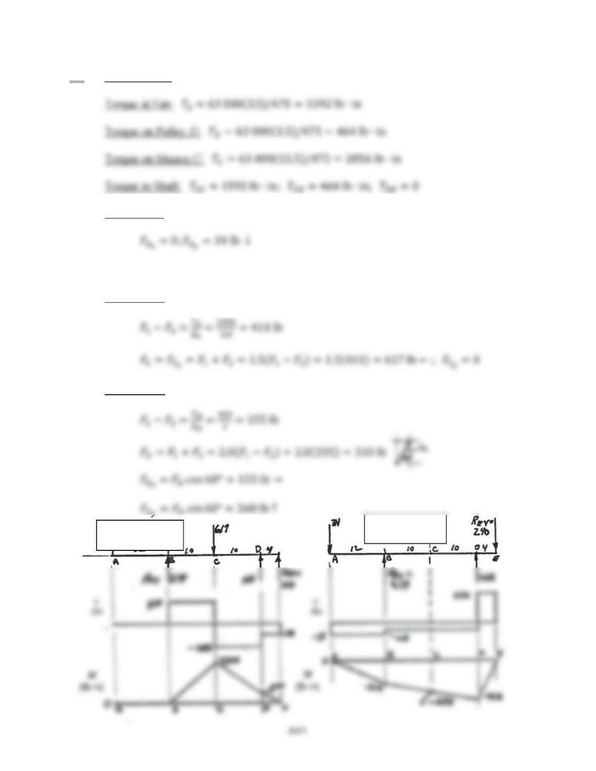
29. Figure P12-9
Forces on Sheave B:
Forces on Gear C:
Forces on Gear D:

330
At C:
Horizonta
l
Vertical
plane
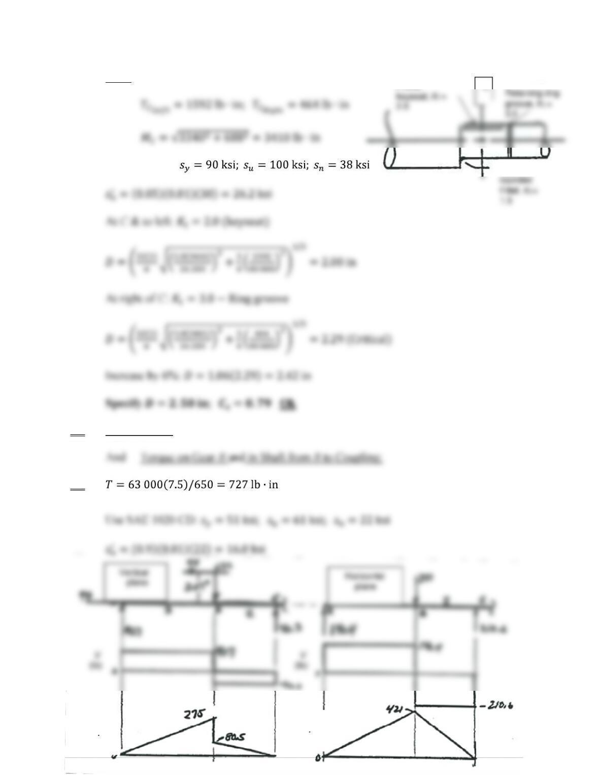
30. Figure P12-17
Forces on A:
The fan would also produce an axial thrust force but its effect on shaft diameter is small.
Forces on C: (V-Belt sheave)
Forces on D: (Flat belt pulley)
Horizontal plane Vertical plane
332
At C:
SAE 1144 CD:
31. Figure P12-31
32.
Well-
Profile
M
(lb in)
M
(lb in)
333
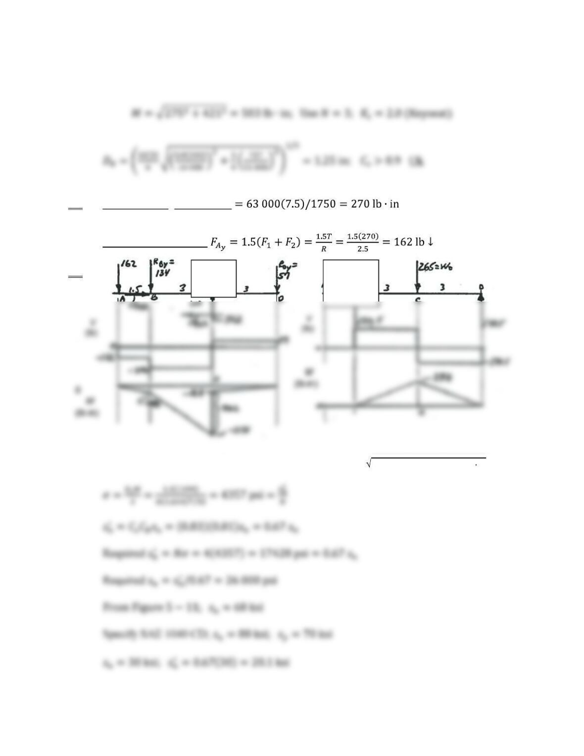
At B:
33. Figure P12-33: Torque at A:
And Forces on Sheave at A:
34.
Assume Torque is Negligible, Use N = 4 MC = (1131)2 + (398)2 = 1199 lb in
Vertical
plane Horizontal
plane
334
Check using Equation 12-24 with
35. Figure P12-35
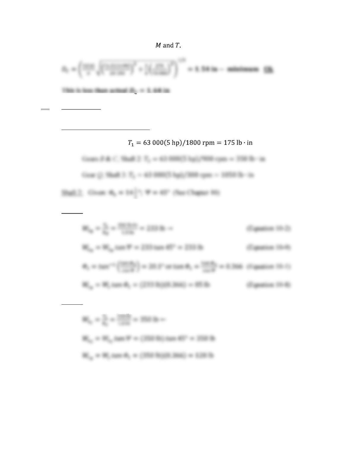
Torques on Gears and in Shafts:
Gear P, Shaft 1:
Gear B:
Gear C: