
INSTRUCTOR’S MANUAL
TO ACCOMPANY
40th Anniversary Edition
DATABASE PROCESSING
Fundamentals, Design, and Implementation
15th Edition
Chapter 6
Transforming Data Models into Database Designs
David M. Kroenke | David J. Auer | Scott L. Vandenberg | Robert C. Yoder

Chapter 6 – Transforming Data Models into Database Designs
Page 6-2
❖ CHAPTER OBJECTIVES
• To understand how to transform data models into database designs
• To be able to identify primary keys and understand when to use a surrogate key
❖ ERRATA
There are no known errors at this time. Any errors that are discovered in the future will
❖ TEACHING SUGGESTIONS
• This is the chapter for which many students have been waiting. It gets into how
tables look based upon the design created in earlier chapters. Start by reviewing the
elements of design in Figure 6-1. Remind students that designs must be
implemented and the implementation must follow the design.

Chapter 6 – Transforming Data Models into Database Designs
Page 6-3
• The companion to referential integrity constraints is referential integrity actions. Most
systems will support cascade and restrict (which we refer to as prohibit in Figure 6-
29).
• Make sure you cover what happens when you use a delete cascade integrity action
with a database structure that has several levels. You can have the cascade action
at level one but the cascade may violate a referential integrity constraint at the next
level. This makes the first level fail. Also, if you use enough delete cascade actions,
you could think you are deleting a single row and potentially delete the entire
database. This is when a rollback can become important.
Chapter 6 – Transforming Data Models into Database Designs
Page 6-4
❖ ANSWERS TO REVIEW QUESTIONS
6.1 Identify the three major tasks for transforming a data model into a database design.
(1) Replacing entities and attributes with tables and columns
6.2 What is the relationship between entities and tables? Between attributes and columns?
6.3 Why is the choice of the primary key important?
The choice of a primary key is important because:
(1) The DBMS will use the primary key to facilitate searching and sorting of table rows.
6.4 What are the three characteristics of an ideal primary key?
6.5 What is a surrogate key? What are its advantages
A surrogate key is a unique, DBMS-supplied identifier used as the primary key of a relation. Its
advantages are:
6.6 When should you use a surrogate key?
A surrogate key is used when a table does not have a unique key, or when a unique key is too

Chapter 6 – Transforming Data Models into Database Designs
Page 6-5
6.7 Describe two disadvantages of surrogate keys.
First, foreign keys that are based on surrogate keys have no meaning to the users. The second
6.8 What is the difference between an alternate key and a candidate key?
6.9 What does the notation LastName (AK2.2) mean?
6.10 Name four column properties.
Four column properties are: null status, data type, default value, and data constraints.
6.11 Explain why primary keys may never be null, but alternate keys can be null.
Primary keys can never be null since each row must have a unique identifier. Alternate keys can
6.12 List five generic data types.
6.13 Describe three ways that a default value can be assigned.
6.14 What is a domain constraint? Give an example.
6.15 What is a range constraint? Give an example.
A range constraint limits the values of a column to a value within a specified range of values. For

Chapter 6 – Transforming Data Models into Database Designs
Page 6-6
6.16 What is an intrarelation constraint? Give an example.
An intrarelation constraint limits the values of a column by a comparison to the values of another
6.17 What is an interrelation constraint? Give an example.
An interrelation constraint limits the values of a column by a comparison to the values of another
6.18 What tasks should be accomplished when verifying normalization of a database design?
6.19 Describe two ways to represent a 1:1 strong entity relationship. Give an example other
than one in this chapter.
A 1:1 strong entity relationship can be represented by placing one of the primary keys as a
6.20 Describe how to represent a 1:N strong entity relationship. Give an example other than
one in this chapter.
A 1:N strong entity relationship can be represented by placing the primary key of the parent entity
(the “1” entity) in the child entity (the “N” entity) as a foreign key.

Chapter 6 – Transforming Data Models into Database Designs
6.21 Describe how to represent an N:M strong entity relationship. Give an example other than
one in this chapter.
An N:M strong entity relationship can be represented by placing the primary key of each of the
6.22 What is an intersection table? Why is it necessary?
An intersection table is a table that stores the foreign key combinations that link two entities in an
6.23 What is the difference between the table that represents an ID-dependent association
entity and an intersection table?
6.24 List four uses for ID-dependent entities.
ID-dependent entities may be used (1) for representing N:M relationships, (2) for creating

Chapter 6 – Transforming Data Models into Database Designs
Page 6-8
6.25 Describe how to represent an association entity relationship. Give an example other than
one in this chapter.
An association entity relationship is represented by storing primary key values of two entities in
6.26 Describe how to represent a multivalued attribute entity relationship. Give an example
other than one in this chapter.
To represent a multivalued attribute, we replace the multivalued attribute with a table and replace
each multivalued attribute with a column in the new table.
6.27 Describe how to represent an archetype/instance entity relationship. Give an example
other than one in this chapter.
To represent a version (Archetype)/instance entity relationship, we place the instances in a
separate table (similar to how we handled the multivalued attribute problem).
6.28 What happens when an instance entity is given a non-ID–dependent identifier? How
does this change affect relationship design?
When an instance entity is given a non-ID-dependent identifier, the relationship changes from an

Chapter 6 – Transforming Data Models into Database Designs
6.29 What happens when the parent in an ID-dependent relationship is given a surrogate
key? What should the key of the child become?
When the parent in an ID-dependent relationship is given a surrogate key, there is no change in
6.30 Describe how to represent a mixed entity relationship. Give an example other than one
in this chapter.
A mixed entity relationship is a combination of strong and ID-dependent designs. We represent it
by:
(1) Creating an ID-dependent relationship between the appropriate parent entity and the ID-
dependent child entity. This will form a typical ID-dependent composite primary key in the ID-
6.31 Describe how to represent a supertype/subtype entity relationship. Give an example
other than one in this chapter.
To represent a supertype/subtype entity relationship, use the same entities in the original database

Chapter 6 – Transforming Data Models into Database Designs
Page 6-10
6.32 Describe two ways to represent a 1:1 recursive relationship. Give an example other than
one in this chapter.
A 1:1 recursive relationship is represented just like a 1:1 strong entity relationship. We place the
primary key as a foreign key in the entity itself. There are two ways to represent the relationship.
6.33 Describe how to represent a 1:N recursive relationship. Give an example other than one
in this chapter.
A 1:N recursive relationship is represented just like a 1:N strong entity relationship. We place the
primary key of the entity acting as the parent entity (the “1” entity) in the entity itself acting as
child entity (the “N” entity) as a foreign key.

Chapter 6 – Transforming Data Models into Database Designs
6.34 Describe how to represent an N:M recursive relationship. Give an example other than
one in this chapter.
An N:M recursive relationship is represented just like an N:M strong entity relationship. We
place the primary key of the entity twice into a separate table, thus forming two 1:N relationships.
6.35 In general, how are ternary relationships represented? Explain how a binary constraint
may impact such a relationship.
Ternary relationships are generally represented by multiple binary relationships. Business rules
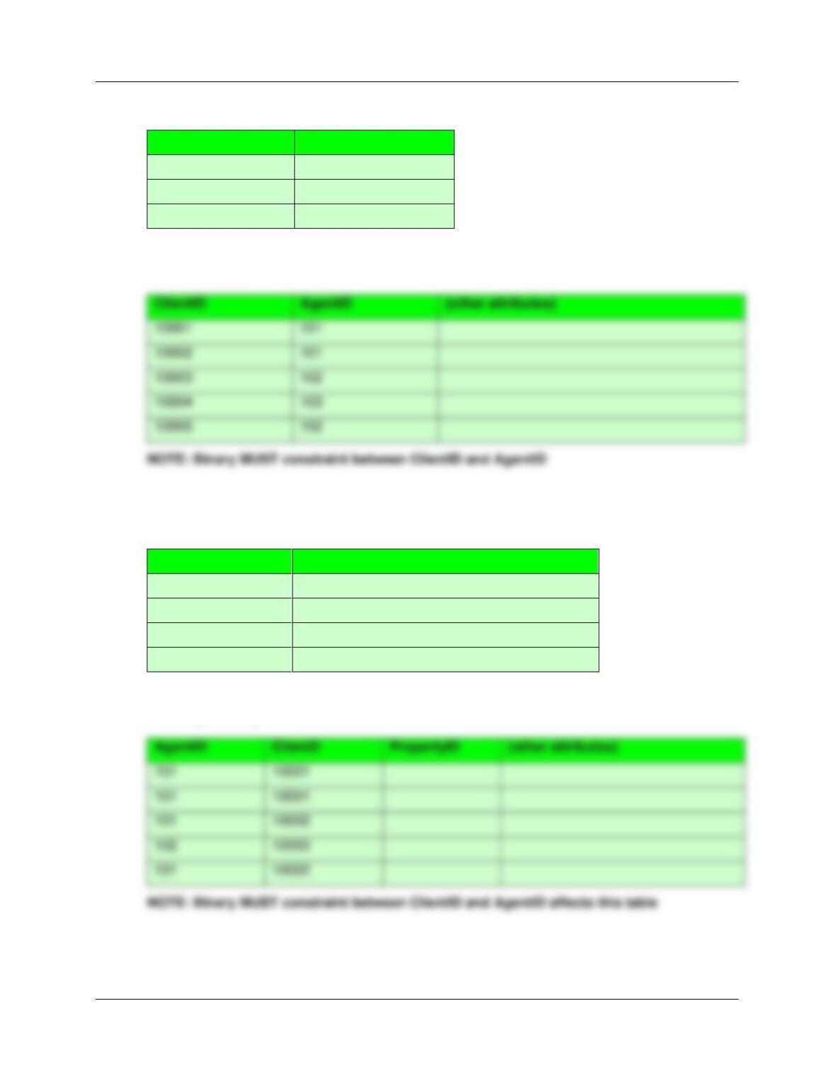
6.36 Describe a MUST constraint. Give an example other than one in this chapter.
In a MUST constraint, the binary relationship indicates combinations that are permitted to occur
in the ternary relationship. For the Real Estate Agency example, how do we represent that
specific clients must be assigned to specific agents? This constraint must be documented and
Chapter 6 – Transforming Data Models into Database Designs
Page 6-12
AGENT TABLE
AgentID
{other attributes}
101
102
103
CLIENT TABLE
PROPERTY TABLE
PropertyID
{other attributes}
100001
100002
100003
100004
AGENT_CLIENT_PROPERTY TABLE
AgentID
ClientD
PropertyID
{other attributes}
101
10001
101
10001
101
10002
102
10003
101
10002
ClientID
AgentID
{other attributes}
10002
101
10003
102
10004
103
10005
102
Chapter 6 – Transforming Data Models into Database Designs
Page 6-13
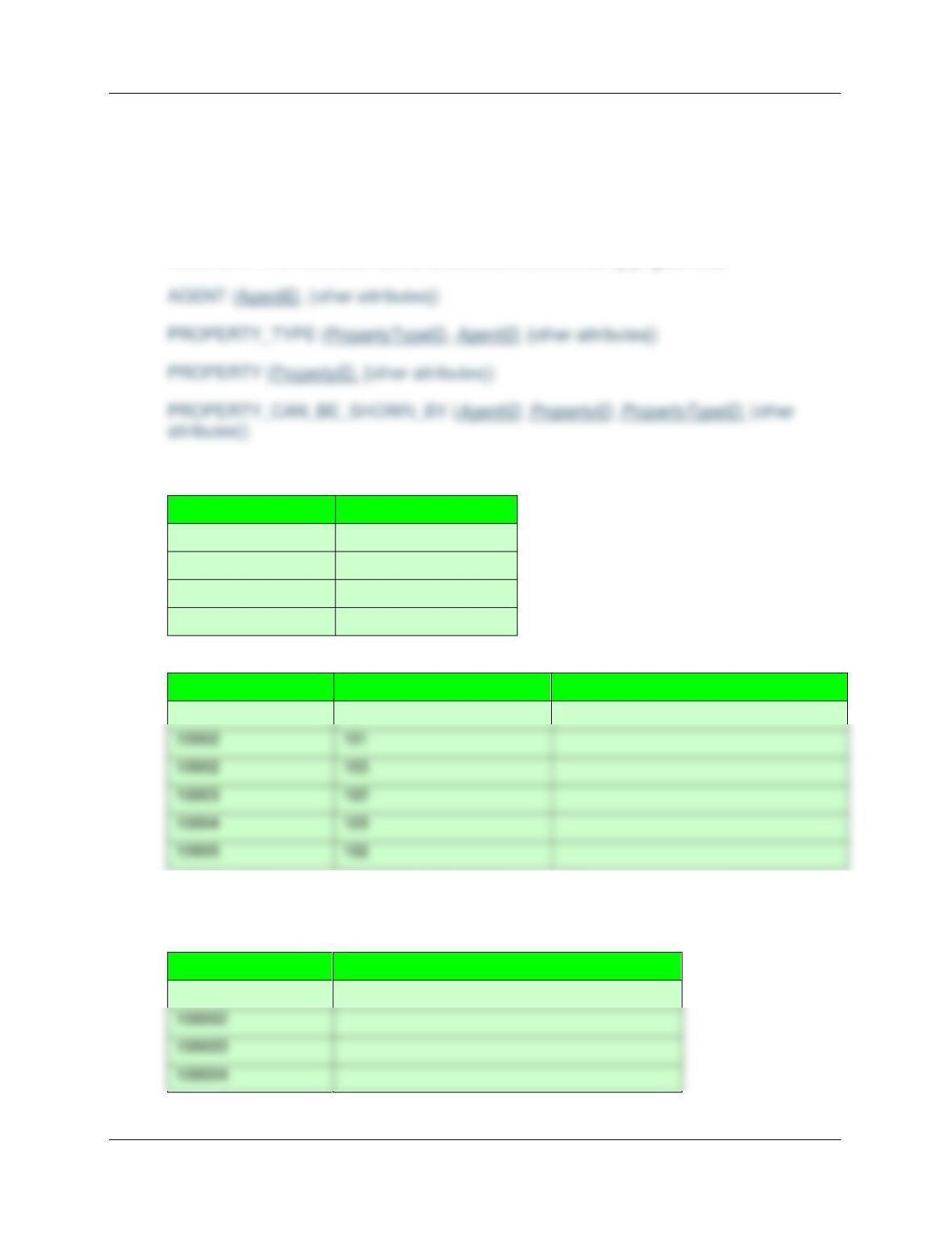
6.37 Describe a MUST NOT constraint. Give an example other than one in this chapter.
In a MUST NOT constraint, the binary relationship indicates combinations that are not allowed
to occur in the ternary relationship.
In the Real Estate Agency example, how do we represent that agents are not qualified to handle
certain properties? Consider the ternary relationship between CLIENT, FINANCING and
PROPERTY. This constraint must be documented and enforced by program code.
AGENT TABLE
AgentID
{other attributes}
101
102
103
104
PROPERTY_TYPE TABLE
PropertyTypeID
NonQualifiedAgentID
{other attributes}
10001
101
10002
101
10002
103
10003
102
10004
103
10005
102
NOTE: Binary MUST NOT constraint between AGENT and PROPERTY_TYPE
PROPERTY TABLE
PropertyID
{other attributes}
100001
100002
100003
Chapter 6 – Transforming Data Models into Database Designs
Page 6-14
PROPERTY_CAN_BE_SHOWN_BY TABLE
AgentID
PropertyID
PropertyTypeID
{other attributes}
102
100001
10002
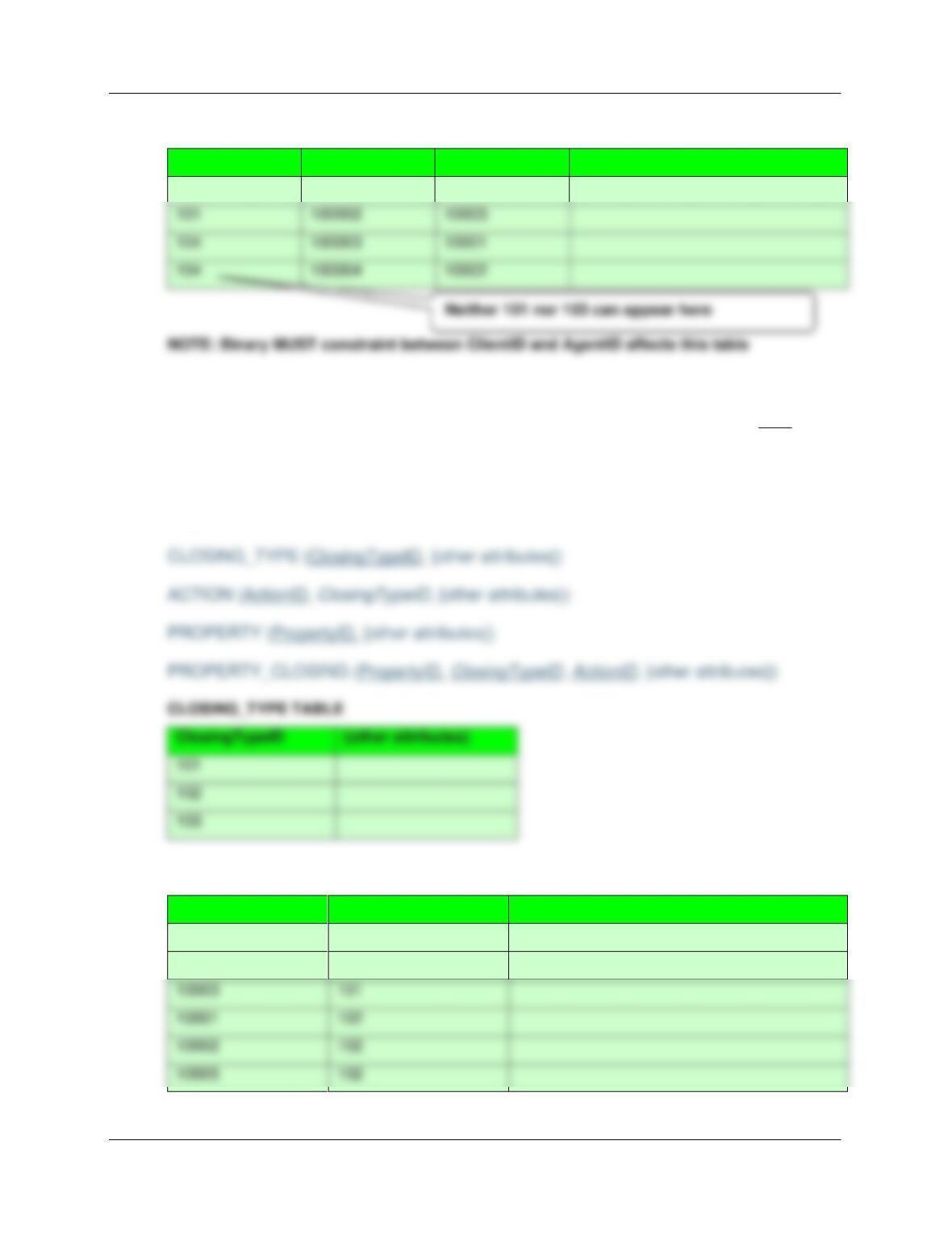
6.38 Describe a MUST COVER constraint. Give an example other than one in this chapter.
In a MUST COVER constraint, the binary relationship indicates all combinations that must
appear in the ternary relationship.
In the Real Estate Agency example, a specific closing type must have a set of specific actions that
must be performed. Consider the ternary relationship between CLIENT, FINANCING and
PROPERTY.
ACTION TABLE
ActionID
ClosingTypeID
{other attributes}
10001
101
10002
101
10003
101
10001
102
10002
102
PROPERTY TABLE
101
100002
10003
104
100003
10001
104
100004
10002
Chapter 6 – Transforming Data Models into Database Designs
PropertyID
{other attributes}
100001
100002
100003
100004
PROPERTY_CLOSING TABLE
PropertyID
ClosingTypeID
ActionID
{other attributes}
100001
101
10001
100001
101
10002
100001
101
10003
100002
102
10001
100002
102
10002
100002
102
NOTE: Binary MUST COVER constraint between ClosingTypeID and ActionID affects this
table
6.39 Explain in general terms what needs to be done to enforce minimum cardinality.
To enforce minimum cardinality we must specify what actions will be taken (or prohibited) on
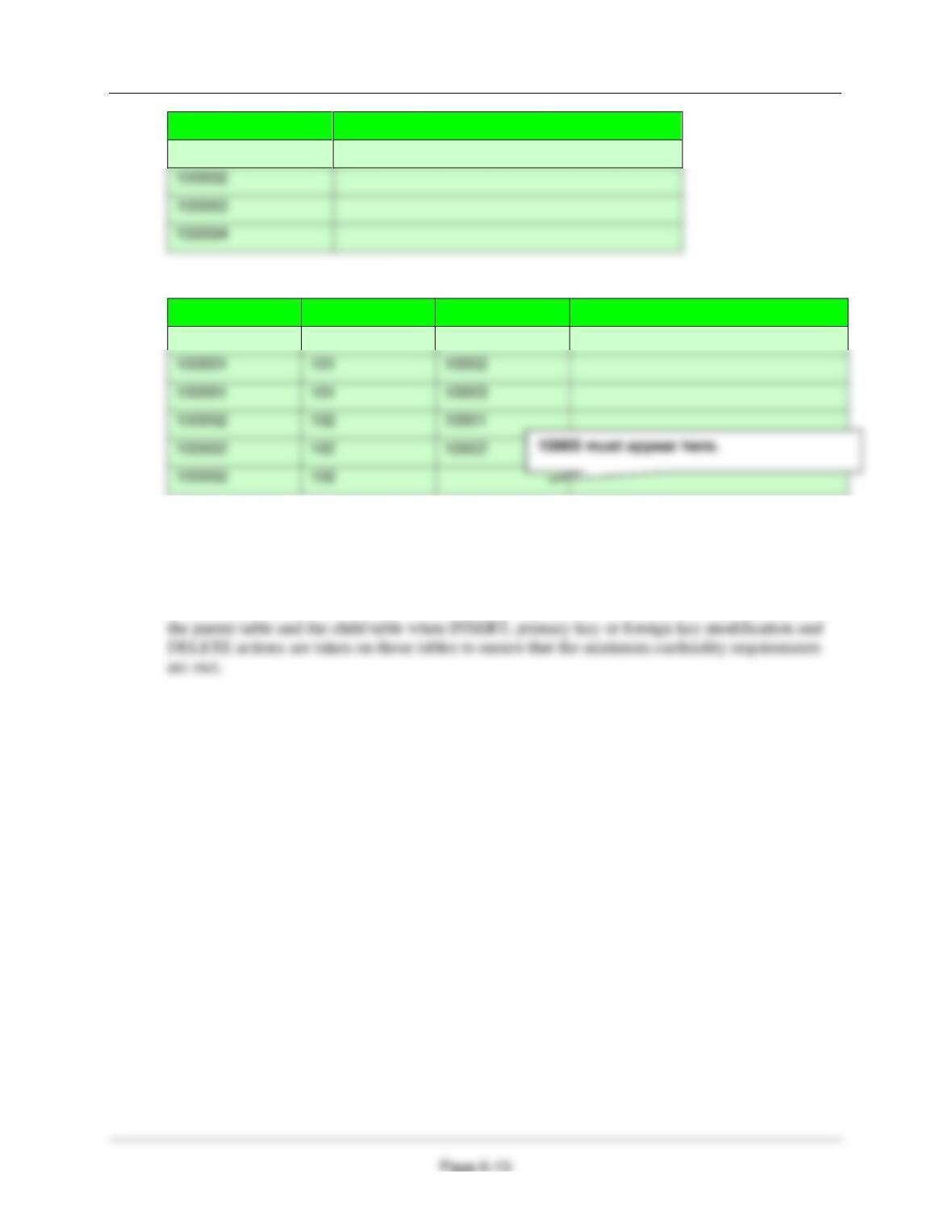
6.40 Explain the need for each of the actions in Figure 6-29(a).
Figure 6-29(a) – Actions When Parent Is Required
When a Parent table is required, every row in the Child table must have a valid, non-null value of
the foreign key.
For the Parent table:
(1) There is no action that needs to be done when a new Parent row is created.
For the Child table:
(1) When a new Child row is created, it must be immediately assigned a valid foreign key
value linking to a valid parent row, or disallow the insert action.
Chapter 6 – Transforming Data Models into Database Designs
Page 6-17
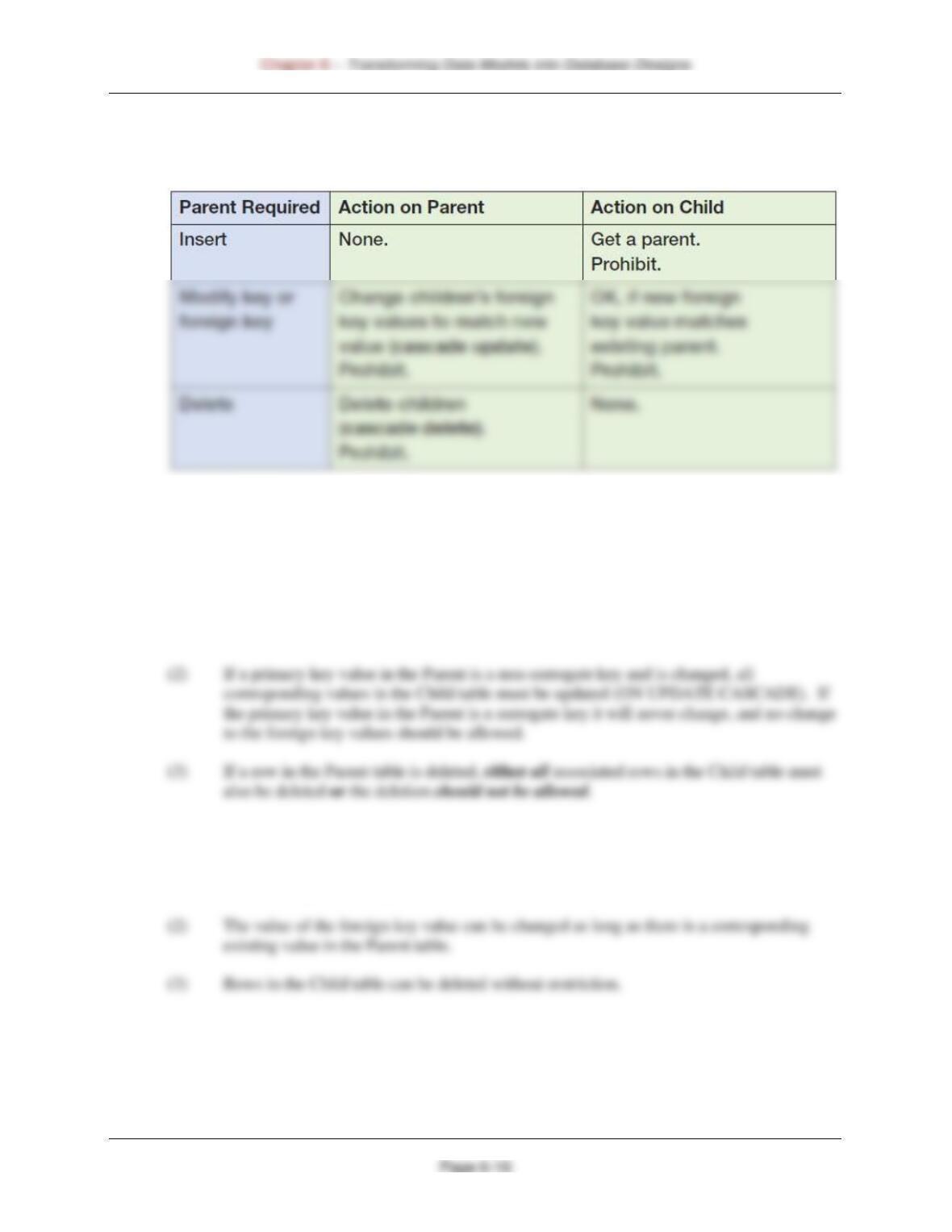
6.41 Explain the need for each of the actions in Figure 6-29(b).
Figure 6-29(b) – Actions When Child Is Required
When a Child table is required, the Parent table must have at least one associated Child table row
at all times.
For the Parent table:
(1) When a new Parent row is created, it must be immediately associated with a row in the
Child table. If this cannot be done, the creation should not be allowed.
For the Child table:
(1) When a new Child row is created, there are no actions that need to be done. The Child
row can exist without a corresponding Parent row. The foreign key in the child may be
null.
Chapter 6 – Transforming Data Models into Database Designs
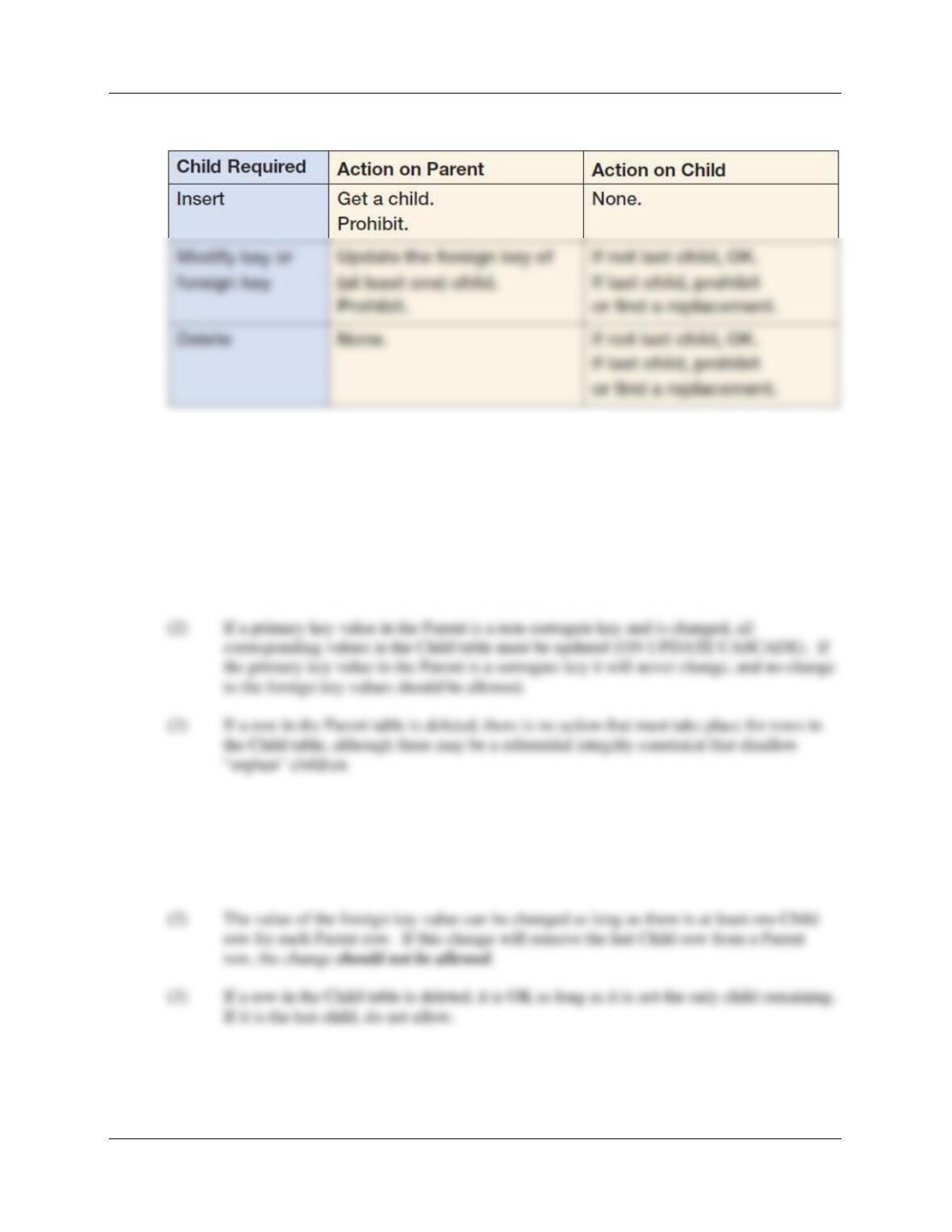
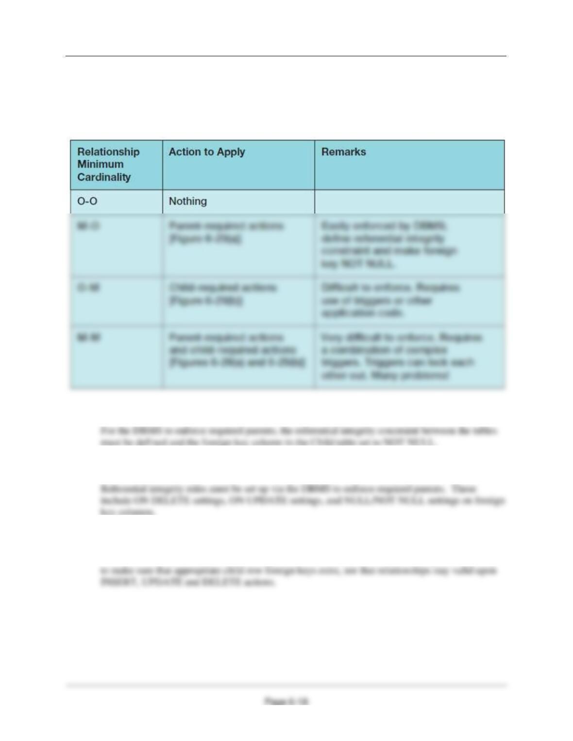
6.42 State which of the actions in Figure 6-29 must be applied for M-O relationships, O-M
relationships, and M-M relationships.
This information is summarized in Figure 6-31 in the text. In general we have (including O:O
relationships):
6.43 Explain what must be done for the DBMS to enforce required parents.
6.44 What design decisions must be made to enforce required parents?
6.45 Explain why the DBMS cannot be used to enforce required children.
The DBMS cannot be used to enforce required children because there is no straightforward way
Chapter 6 – Transforming Data Models into Database Designs
6.46 What is a trigger? How can triggers be used to enforce required children?
Triggers (which will be discussed in depth in Chapter Seven) are modules of code that are stored
6.47 Explain why the enforcement of M-M relationships is particularly difficult.
The enforcement of M-M relationships is particularly difficult because two sets of constraints
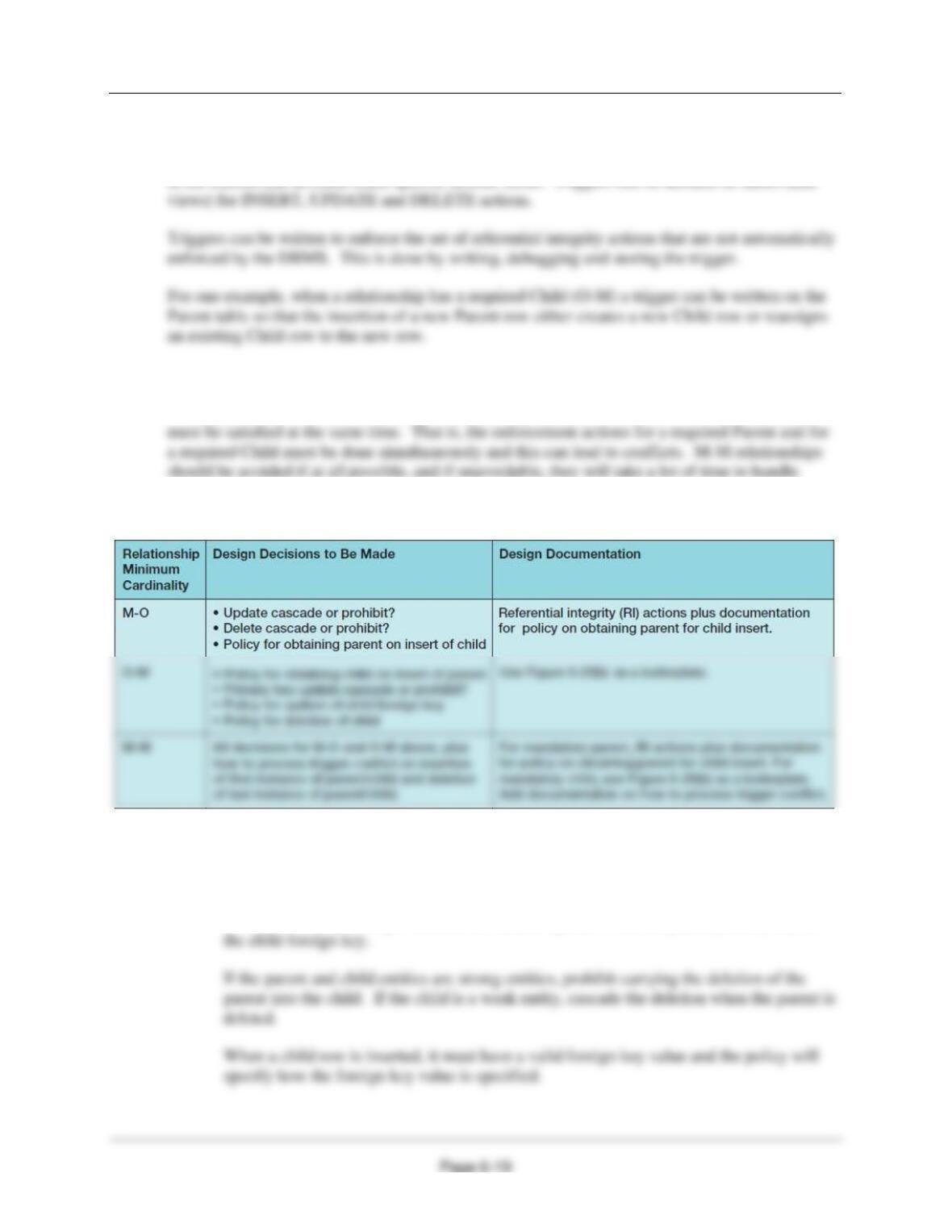
6.48 Explain the need for each of the design decisions in Figure 6-34.
(1) M-O design decisions – The M-O design decisions are based on a mandatory parent.
If the primary key is a surrogate key (or equivalent), updates should be prohibited since
the key will never change. Otherwise, cascade updates from the parent primary key to

Chapter 6 – Transforming Data Models into Database Designs
(2) O-M design decisions — The O-M design decisions are based on a mandatory child.
If the child is required, there must be a child row associated with a parent row as soon as
the parent row is created. The policy will specify how this is done.
(3) M-M design decisions — The M-M design decisions are based on both a mandatory
parent and a mandatory child.
All of the above considerations apply. However, the requirements that a parent obtain a