
Chapter Five – Database Design
N:M Recursive; If agents in the community where PNWREA is located want to acquire property
themselves, they are required to use another agent (not necessarily at PNWREA) to act as the
selling agent on the deal. If an agent makes several purchases, he or she can use a different
selling agent for each deal. Further, that agent may be the selling agent in other deals.
However, no agent is required to buy property, so working with a selling agent is optional.
Similarly, no agent is required to be the selling agent in this type of a transaction. Therefore,
each agent is optionally associated with many other selling agents, and may optionally be a
selling agent to many other agents.
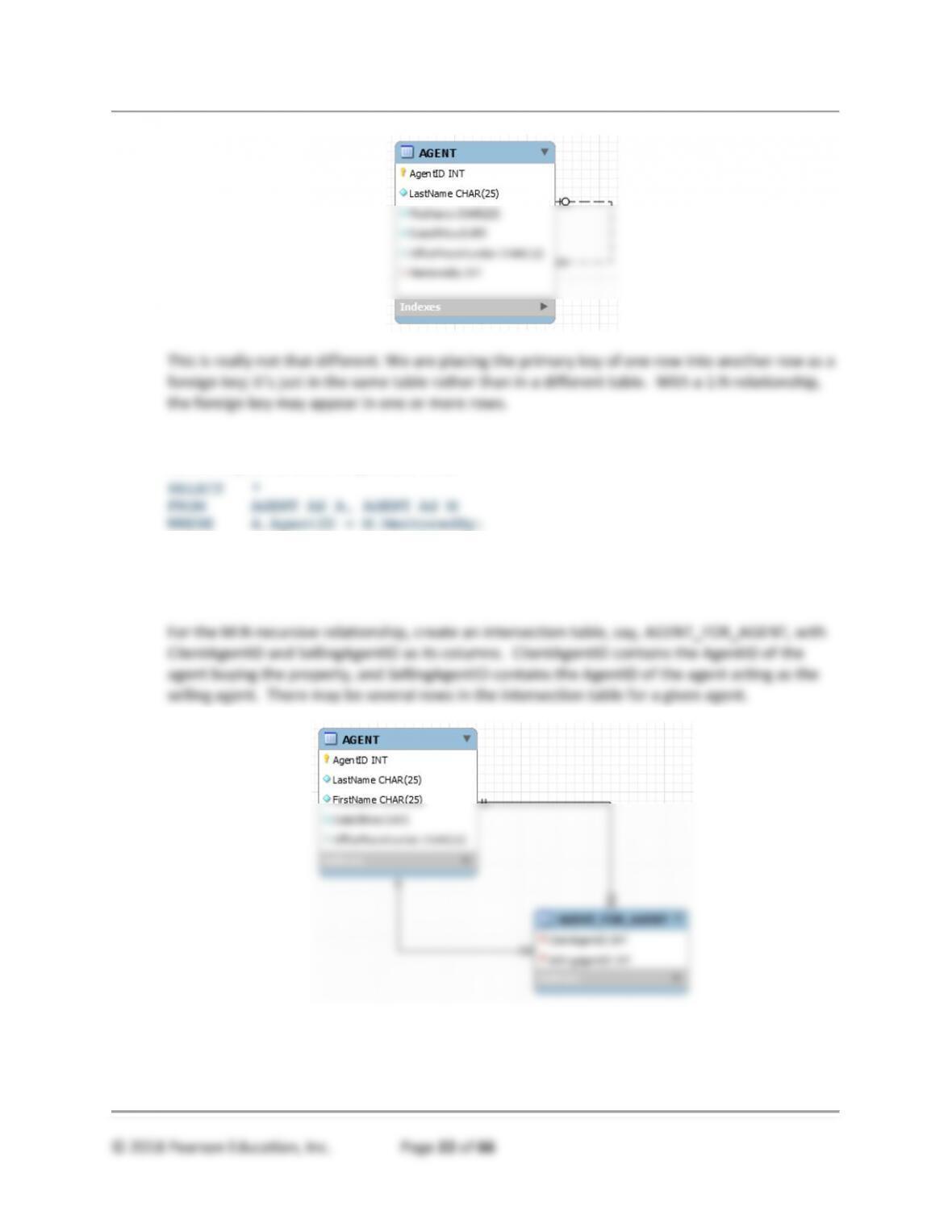
5.30 Show how to represent the 1:1 recursive relationship in your answer to question 5.29.
How does this differ from the representation of 1:1 nonrecursive relationships?
See MySQL Workbench file DBC-e08-RQ-5-30.mwb.
5.31 Code an SQL statement that creates a table with all columns from the parent and child
tables in your answer to question 5.30.
5.32 Show how to represent a 1:N recursive relationship in your answer to question 5.29.
How does this differ from the representation of 1:N nonrecursive relationships?
See MySQL Workbench file DBC-e08-RQ-5-32.mwb.
Chapter Five – Database Design
5.33 Code an SQL statement that creates a table with all columns from the parent and child
tables in your answer to question 5.32.
5.34 Show how to represent the M:N recursive relationship in your answer to question 5.29.
How does this differ from the representation of M:N nonrecursive relationships?
See MySQL Workbench file DBC-e08-RQ-5-34.mwb.
This is basically the same technique used for any intersection table relation used for any M:N
relationships. The only difference is that values in the intersection table come from only one
source relation.

Chapter Five – Database Design
5.35 Code an SQL statement that creates a table with all columns from the parent and child
tables in your answer to question 5.34. Code an SQL statement using a left outer join
that creates a table with all columns from the parent and child tables. Explain the
difference between these two SQL statements.
The basic SQL join of the two tables is:
The SQL left outer join of the two tables is:
The first query will only show agents who have purchased property. The second query
statement will show all agents, regardless of whether or not they have purchased property.

Chapter Five – Database Design
ANSWERS TO EXERCISES
5.36 Consider the following table, which holds data about employee project assignments:
Assume that ProjectNumber determines ProjectName, and explain why this relation is
not normalized. Demonstrate an insertion anomaly, a modification anomaly, and a
deletion anomaly. Apply the normalization process to this relation. State the referential
integrity constraint.
The ASSIGN relation is not normalized because there is a determinant, ProjectNumber, which is
not a candidate key.
Normalized relations:
where

Chapter Five – Database Design
5.37 Consider the following relation that holds data about employee assignments:
ASSIGNMENT (EmployeeNumber, ProjectNumber, ProjectName, HoursWorked)
Assume that ProjectNumber determines ProjectName, and explain why this relation is
not normalized. Demonstrate an insertion anomaly, a modification anomaly, and a
deletion anomaly. Apply the normalization process to this relation. State the referential
integrity constraint.
The solution is nearly the same as the solution for question 5.36. The only difference is the
primary key for the normalized ASSIGN relation:
The ASSIGN relation is not normalized because there is a determinant, ProjectNumber, that is
not a candidate key.
Normalized relations:
where
5.38 Explain the difference between the two ASSIGNMENT tables in questions 5.36 and
5.37. Under what circumstances is the table in question 5.36 more correct? Under what
circumstances is the table in question 5.37 more correct?

Chapter Five – Database Design
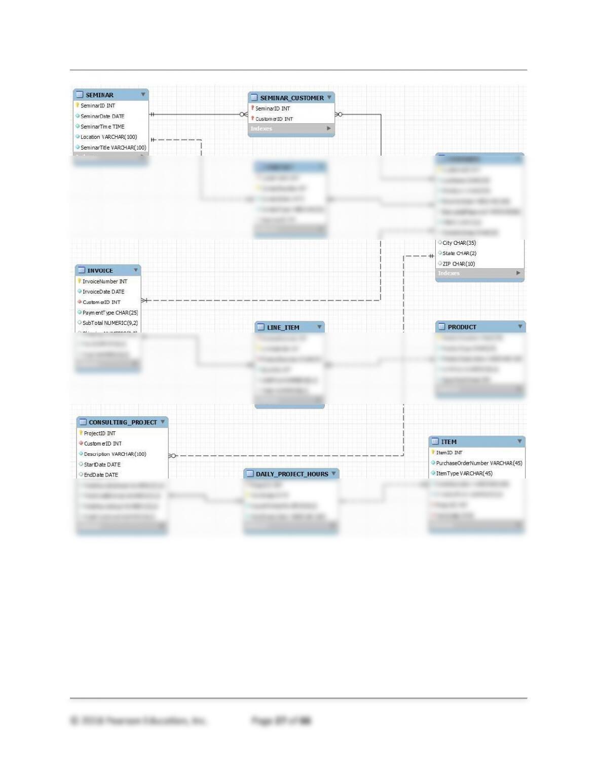
5.39 Create a relational database design for the data model you developed for question 4.30.
See the E-R diagram on the next page.
SEMINAR (SeminarID, SeminarDate, SeminarTime, Location, SeminarTitle)
CUSTOMER (CustomerID, LastName, FirstName, EmailAddress, EncryptedPassword, Phone,
StreetAddress, City, State, Zip)
SEMINAR_CUSTOMER (SeminarID, CustomerID)
Where referential integrity constraints are:
SeminarID in SEMINAR_CUSTOMER must exist in SeminarID in SEMINAR
CustomerID in SEMINAR_CUSTOMER must exist in CustomerID in CUSTOMER
CustomerID in CONTACT must exist in CustomerID in CUSTOMER
Chapter Five – Database Design
© 2018 Pearson Education, Inc. Page 27 of 66
Chapter Five – Database Design
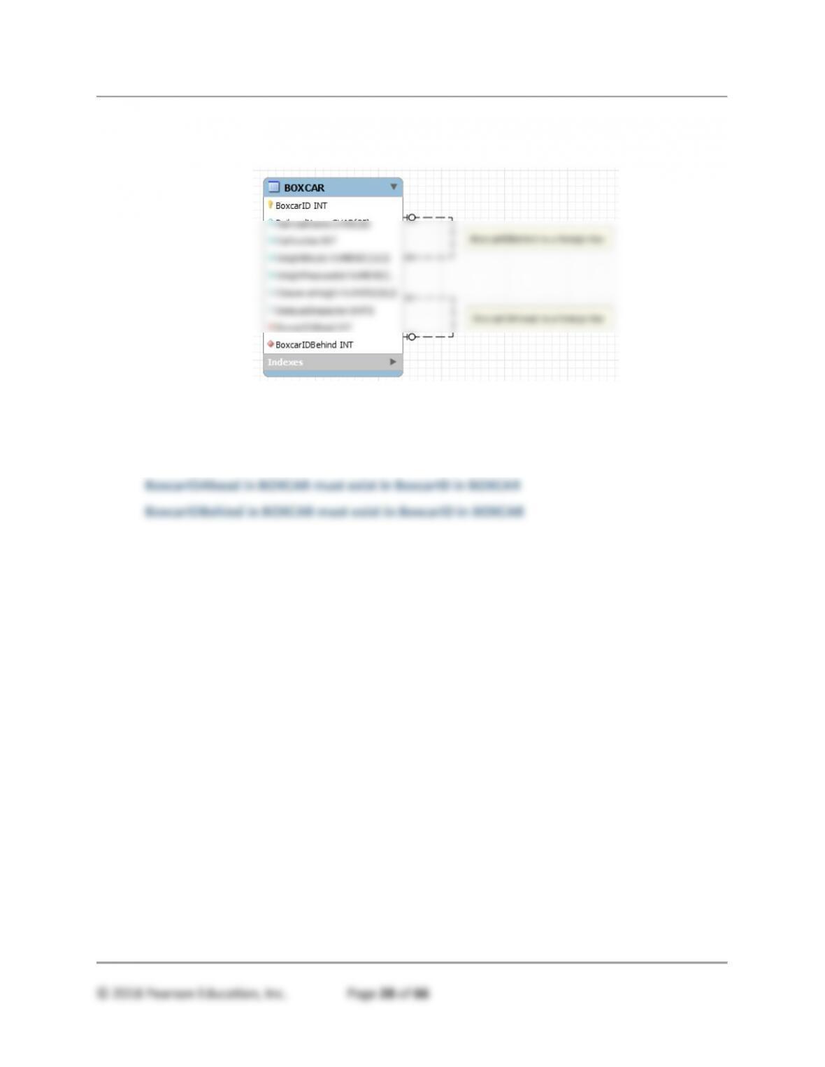
5.41 Create a relational database design for the data model you developed for question 4.31.
See MySQL Workbench file DBC-e08-EX–5-41.mwb.
BOXCAR (BoxcarID, RailroadName, CarNumber, WeightEmpty, WeightMaxLoaded,
ClearanceHeight, DateLastInspection, BoxcarIDAhead, BoxcarIDBehind)
Where:
Chapter Five – Database Design
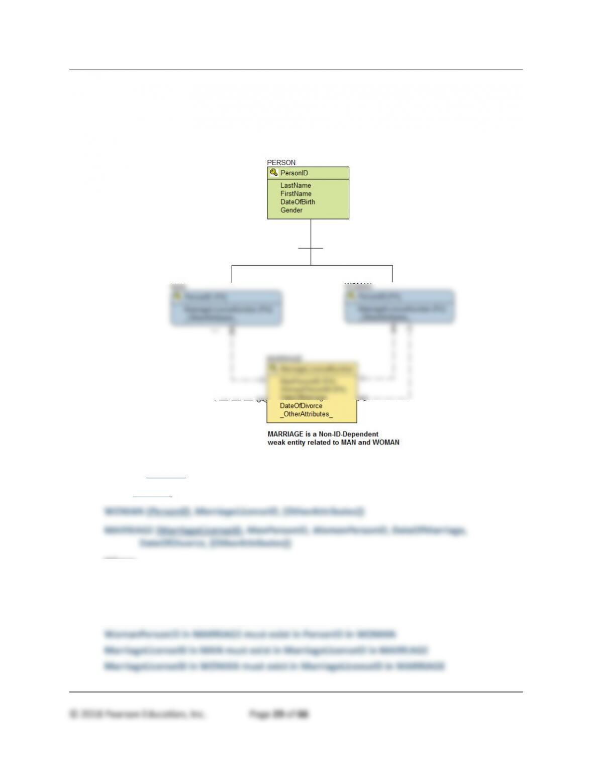
5.42 Create a relational database design for the data model you developed for question 4.32.
This solution is shown as drawn by ERwin instead of MySQL Workbench because of MySQL
Workbench’s lack of supertype/subtype tools. See Review Question 5.28 for a suggested
workaround for MySQL Workbench
PERSON (PersonID, LastName, FirstName, DateOfBirth, Gender)
MAN (PersonID, MarriageLicenseID, {OtherAttributes})
Where:
PersonID in MAN must exist in PersonID in PERSON
PersonID in WOMAN must exist in PersonID in PERSON
ManPersonID in MARRIAGE must exist in PersonID in MAN

Chapter Five – Database Design
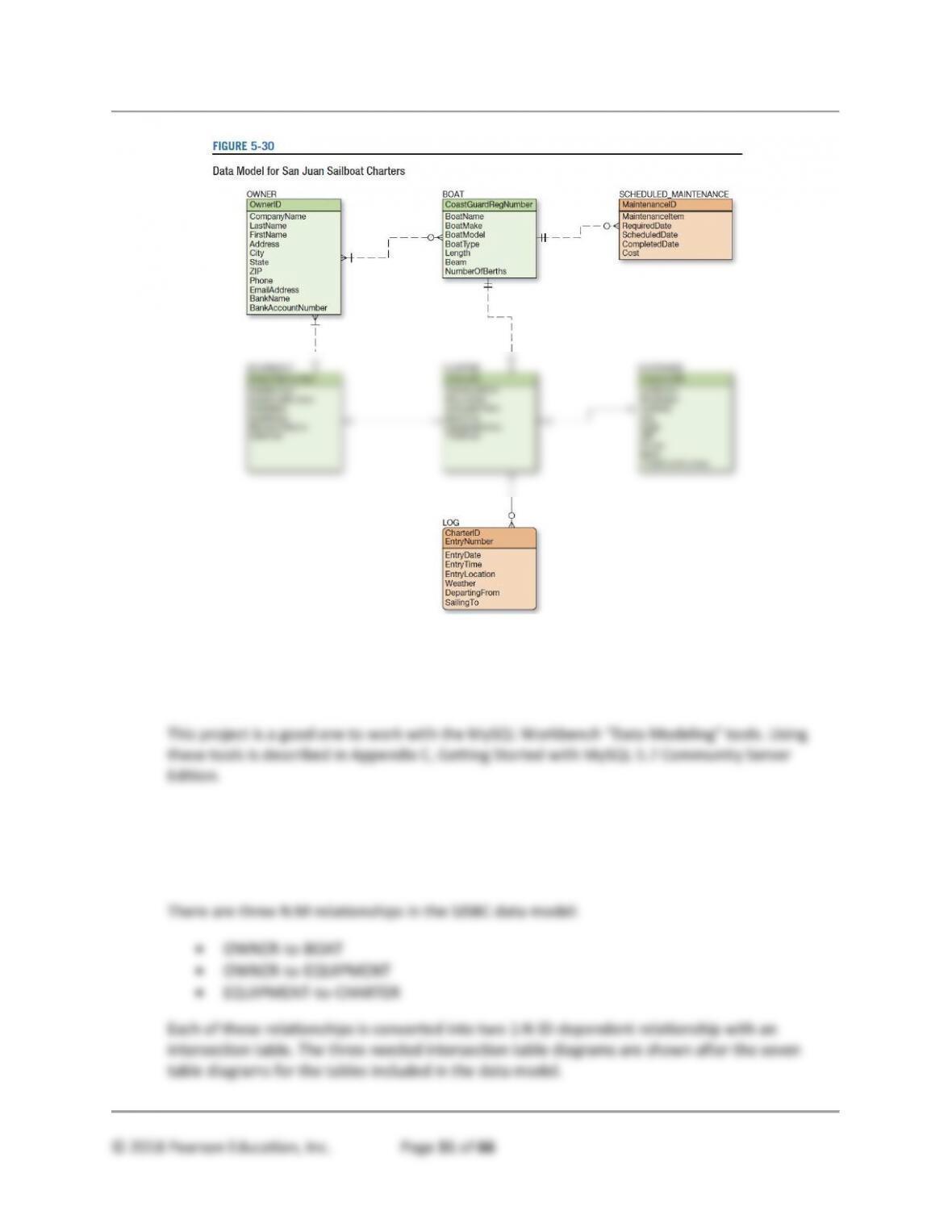
ANSWERS TO SAN JUAN SAILBOAT CHARTERS CASE QUESTIONS
San Juan Sailboat Charters (SJSBC) is an agency that leases (charters) sailboats.
SJSBC does not own the boats. Instead, SJSBC leases boats on behalf of boat owners
who want to earn income from their boats when they are not using them, and SJSBC
charges the owners a fee for this service. SJSBC specializes in boats that can be used
for multiday or weekly charters. The smallest sailboat available is 28 feet in length and
the largest is 51 feet in length.
Each sailboat is fully equipped at the time it is leased. Most of the equipment is provided
at the time of the charter. Most of the equipment is provided by the owners, but some is
provided by SJSBC. The owner-provided equipment includes equipment that is attached
to the boat, such as radios, compasses, depth indicators and other instrumentation,
Keeping track of equipment is an important part of SJSBC’s responsibilities. Much of the
equipment is expensive, and those items not physically attached to the boat can be
easily damaged, lost, or stolen. SJSBC holds the customers responsible for all of the
boat’s equipment during the period of the charter.
SJSBC likes to keep accurate records of its customers and charters, and customers are
required to keep a log during each charter. Some itineraries and weather conditions are
more dangerous than others, and the data from these logs provides information about
the customer experience. This information is useful for marketing purposes, as well as
for evaluating a customer’s ability to handle a particular boat and itinerary.
Chapter Five – Database Design
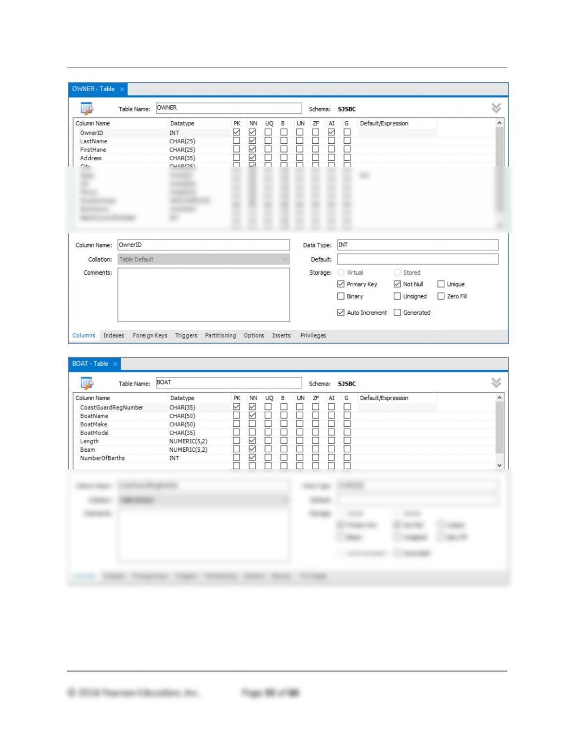
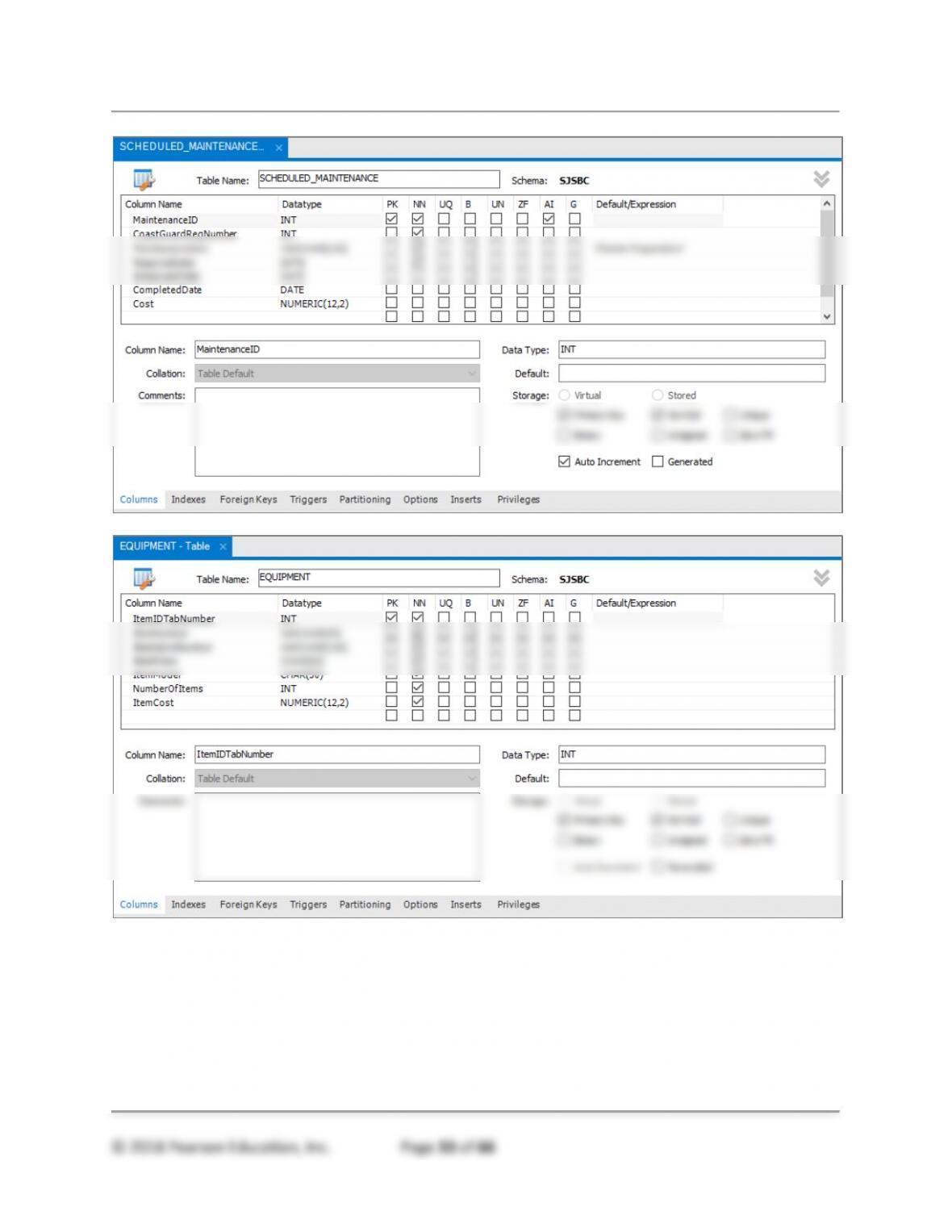
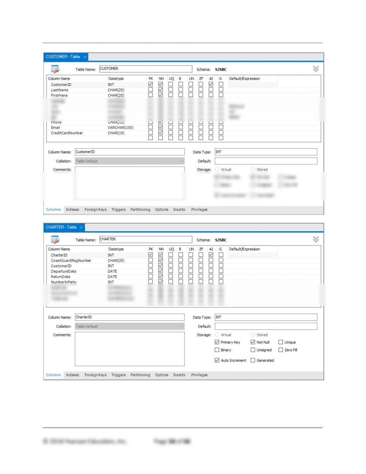
A Convert this data model to a database design. Specify tables, primary keys, and foreign
keys. Using Figures 5-26 and 5-28 as guides, specify column properties.
See MySQL Workbench file DBC-e08-CH05-SJSBC.mwb.
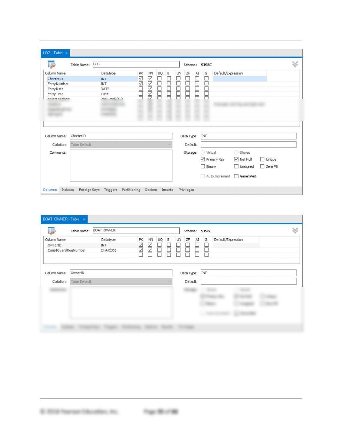
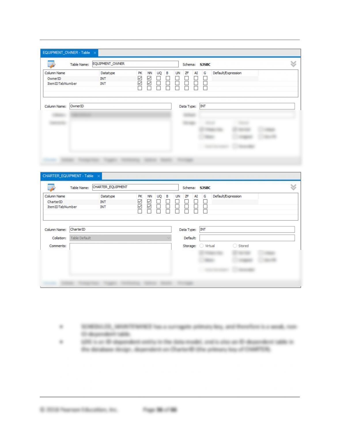
Based on the SJSBC data model, the following tables exist. The following MySQL Workbench
table diagrams show primary keys (gold key symbol and PK = Primary Key), foreign keys fired
diamond), and column properties including column name, data type, required (NN = NOT NULL),
and Default value. Surrogate keys are indicated by AI = AUTO_INCREMENT.
Chapter Five – Database Design
Chapter Five – Database Design
Chapter Five – Database Design
Chapter Five – Database Design
INTERSECTION TABLES:
Chapter Five – Database Design
© 2018 Pearson Education, Inc. Page 36 of 66
B Describe how you have represented weak entities, if any exist.
There are two weak entities:
C Describe how you have represented supertype and subtype entities, if any exist.
There are no supertype and subtype entities in this design
Chapter Five – Database Design
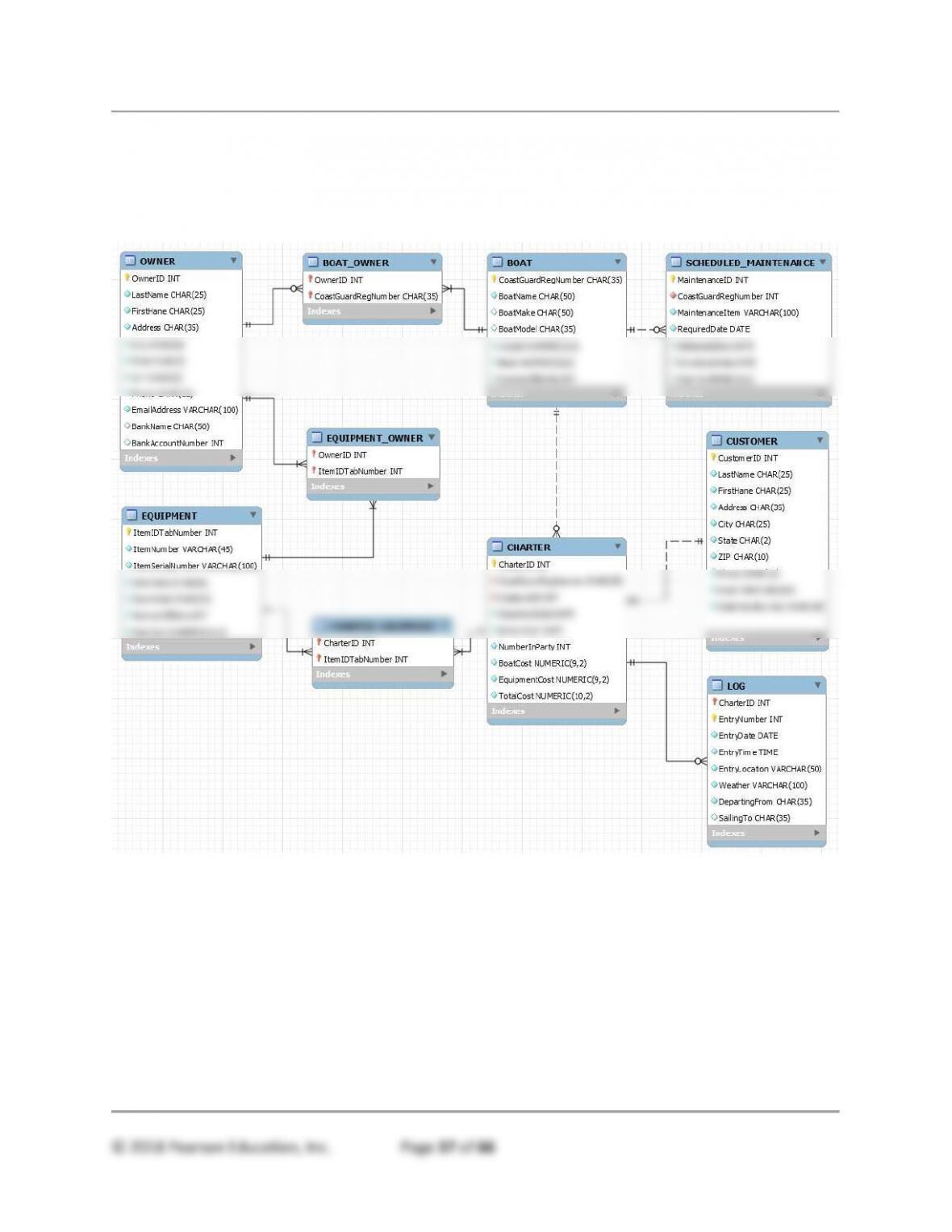
D Create a visual representation of your database design as a Crow’s Foot E-R diagram
similar to the one in Figure 5-27.
See MySQL Workbench file DBC-e08-CH05-SJSBC.mwb.

Chapter Five – Database Design
E Document referential integrity constraint enforcement, using Figure 5-29 as a guide.
Relationship
Referential Integrity
Constraint
Cascading Behavior
PARENT
CHILD
ON
UPDATE
ON
DELETE
OWNER
BOAT_OWNER
OwnerID in BOAT_OWNER
must exist in OwnerID in
OWNER
NO
YES
BOAT
BOAT_OWNER
CoastGuardRegNumber in
BOAT_OWNER must exist
in CoastGuardRegNumber
in BOAT
YES
YES
OWNER
EQUIPMENT_OWNER
OwnerID in
EQUIPMENT_OWNER
must exist in OwnerID in
OWNER
NO
YES
EQUIPMENT
EQUIPMENT_OWNER
ItemIDTagNumber in
EQUIPMENT_OWNER
must exist in
ItemIDTagNumber in
EQUIPMENT
YES
YES
CHARTER
CHARTER_EQUIPMENT
CharterID in
CHARTER_EQUIPMENT
must exist in CharterID in
CHARTER
NO
YES
EQUIPMENT
CHARTER_EQUIPMENT
ItemIDTagNumber in
CHARTER_EQUIPMENT
must exist in
ItemIDTagNumber in
EQUIPMENT
YES
YES
BOAT
SCHEDULED_
MAINTENANCE
CoastGuardRegNumber in
SCHEDULED_
MAINTENANCE must exist
in CoastGuardRegNumber
in BOAT
YES
NO
CUSTOMER
CHARTER
CustomerID in CHARTER
must exist in CustomerID in
CUSTOMER
NO
NO
CHARTER
LOG
CharterID in LOG must exist
in CharterID in CHARTER
NO
YES
Chapter Five – Database Design
ANSWERS TO WRITER’S PATROL CASE QUESTIONS
Answer the Writer’s Patrol Case Questions in Chapter 4 if you have not already done so.
Design a database for your data model from Chapter 4. Your design should include a
specification of tables and (using Figure 5-26 and 5-28 as guides) column properties, as
well as primary, candidate, and foreign keys. Create a visual representation of your
database design as an IE Crow’s Foot E-R diagram similar to the one in Figure 5-27.
Document your referential integrity constraint enforcement in the format shown in
Figure 5-29.
Patrol.mwb.

Chapter Five – Database Design
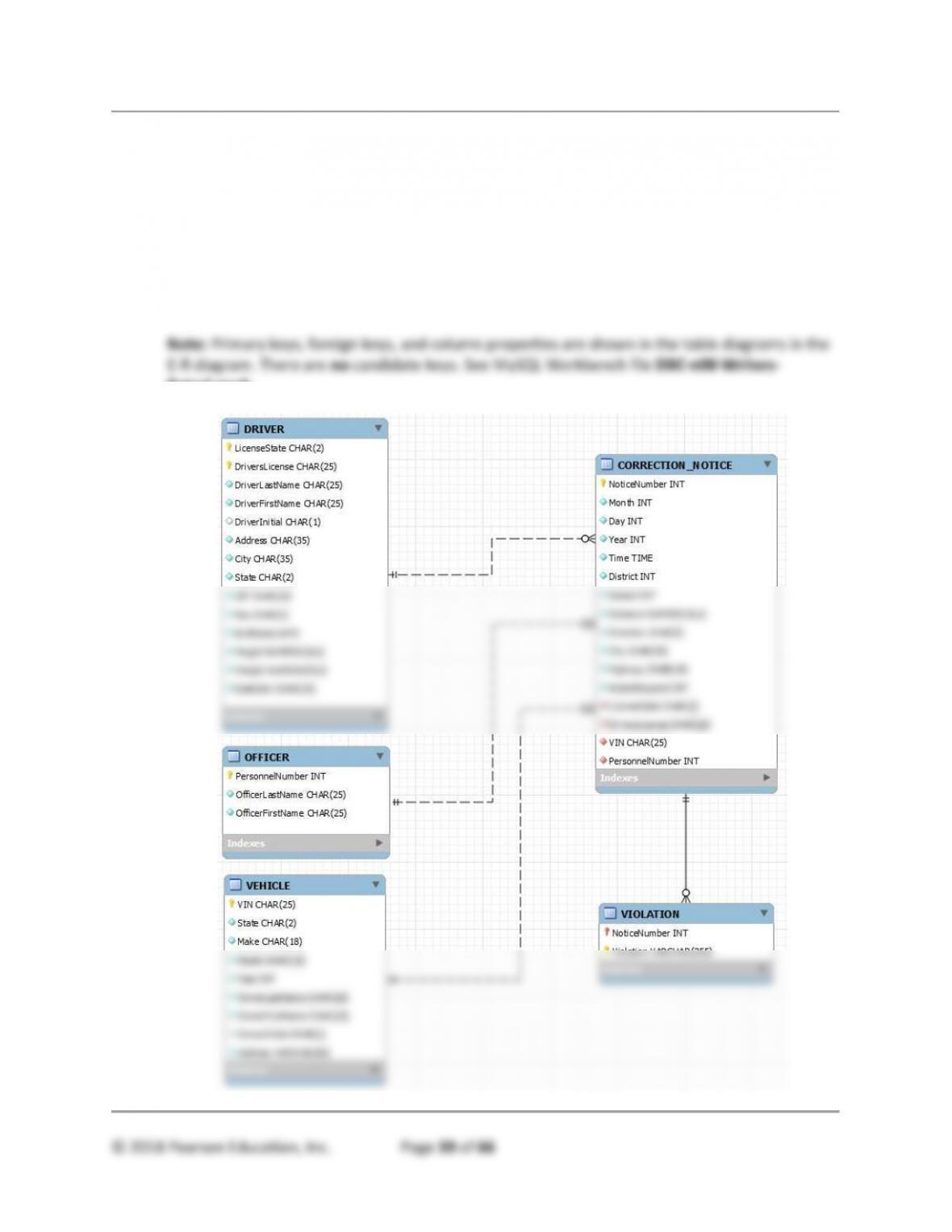
The E-R Crow’s Foot model above is based on the following data:
RELATIONSHIP
CARDINALITY
[Blue = Inferable]
PARENT
CHILD
TYPE
MAX
MIN
DRIVER
CORRECTION_NOTICE
Strong
1:N
M-O
OFFICER
CORRECTION_NOTICE
Strong
1:N
M-O
VEHICLE
CORRECTION_NOTICE
Strong
1:N
M-O
CORRECTION_NOTICE
VIOLATION
ID-Dependent
Multi-valued
1:N
M-O
Relationship
Referential Integrity
Constraint
Cascading
Behavior
PARENT
CHILD
ON
UPDATE
ON
DELETE
DRIVER
CORRECTION_NOTICE
(LicenseState,
DriversLicense) in
DRIVER must exist in
(LicenseState,
DriversLicense) in
CORRECTION_NOTICE
NO
NO
OFFICER
CORRECTION_NOTICE
PersonnelNumber in
OFFICER must exist in
PersonnelNumber in
CORRECTION_NOTICE
NO
NO
VEHICLE
CORRECTION_NOTICE
VIN in VEHICLE must
exist in VIN in
CORRECTION_NOTICE
NO
NO
CORRECTION_NOTICE
VIOLATION
NoticeNumber in
CORRECTION_NOTICE
must exist in
NoticeNumber in
VIOLATION
NO
YES