Page 1 of 52
Database Concepts
8th Edition
David M. Kroenke • David J. Auer • Scott L. Vandenberg • Robert C. Yoder
Instructor’s Manual
Prepared by Robert C. Yoder and David J. Auer
CHAPTER FOUR
DATA MODELING AND THE
ENTITY-RELATIONSHIP MODEL

All rights reserved. No part of this publication may be reproduced, stored in a retrieval system, or transmitted,
in any form or by any means, electronic, mechanical, photocopying, recording, or otherwise, without the prior
written permission of the publisher. Printed in the United States of America.
Instructor’s Manual to accompany:
Database Concepts (8th Edition)
David M. Kroenke • David J. Auer • Scott L. Vandenberg • Robert C. Yoder

Chapter Four – Data Modeling and the Entity-Relationship Model
CHAPTER OBJECTIVES
• Learn the basic stages of database development
• Understand the purpose and role of a data model
• Know the principal components of the E-R data model
• Understand how to interpret traditional E-R diagrams
• Understand how to interpret the Information Engineering (IE) model’s Crow’s Foot E–
R diagrams
• Learn to construct E-R diagrams
• Know how to represent 1:1, 1:N, N:M, and binary relationships with the E-R model
• Understand two types of weak entities and know how to use them
• Understand nonidentifying and identifying relationships and know how to use them
• Know how to represent subtype entities with the E-R model
• Know how to represent recursive relationships with the E-R model
• Learn how to create an E-R diagram from source documents
CHAPTER ERRATA
There are no known errors at this time. Any errors that are discovered in the future will
be reported and corrected in the online DBC e08 Errata document, which will be
available at http://www.pearsonhighered.com/kroenke.
THE ACCESS WORKBENCH
Solutions to the Access Workbench exercises may be found in Solutions to all Sections:
The Access Workbench, which is a separate document within the Instructor’s Manual.
NOTES ON MICROSOFT WINDOWS 10
This book uses the Microsoft Windows 10 operating system as the basis for screenshots
and step-by-step instructions. However, with Windows 10, Microsoft has introduced a
continuous update system that has already resulted in some fundamental differences in
how different versions of Windows 10 look and operate.
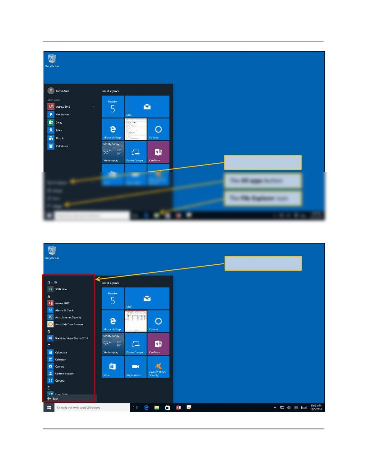
For example, in the original version of Microsoft Windows 10, clicking the Windows
Start button (or pressing the Windows key on the keyboard) displayed the menu shown
in Figure 1. In this menu, we need to click the All apps button in order to see the All
apps menu shown in Figure 2.
Chapter Four – Data Modeling and the Entity-Relationship Model
Page 4 of 52
Figure 1 – Windows 10 Main Menu
The All apps button
The File Explorer button
The File Explorer icon
The All apps menu
Chapter Four – Data Modeling and the Entity-Relationship Model
Page 5 of 52
Figure 2 – Windows 10 All Apps Menu
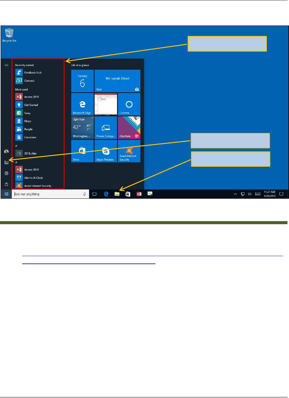
Figure 3 – Windows 10 Anniversary Update Main Menu with All Apps Menu Included
Microsoft then released the Windows 10 Anniversary Update (Feature update to
Windows 10, version 1607) (see the blog discussion at
https://blogs.windows.com/windowsexperience/2016/08/02/how-to-get-the-windows-10–
anniversary-update/#K1CZuiw4auiuE9A5.97 ). One of the changes introduced in the
Anniversary Update was a major change to the menu system. Now, as shown in
Figure 3, the All apps menu is immediately available when the Start button is used (or
the keyboard Windows key is pressed).
Therefore, note that the step by step instructions in this book may need to be altered for
your use depending upon which version of Microsoft Windows 10 you or your students
are using!
We recommend that you update Windows 10 to the Windows 10 Anniversary Update
(Feature update to Windows 10, version 1607), and make sure it is patched with all
updates to that version (at a minimum patched to Windows 10 Version 1607 update for
August 23, 2016 (KB3176936), and the Windows 10 Version 1607 cumulative update for
September 29, 2016 (KB3194496). We also recommend using the 32-bit version of
Microsoft Office. This insures that all the examples discussed in this book will function
properly.
The All apps menu
The File Explorer button
The File Explorer icon

Chapter Four – Data Modeling and the Entity-Relationship Model
Page 6 of 52
TEACHING SUGGESTIONS
• A good way to introduce the chapter is by discussing the relationship between
systems analysis and design and database design. If a systems analysis and design
course is a prerequisite for the course, make the connection to what the students
covered in that class. If you do not have such a prerequisite, you may want to add a
lecture or two that introduces some of that material.
• Very important in this chapter is that a database is a model of a user’s view of the
world. Remember, the only question is “How well does it fit the mental models of the
people who are going to use the system?” Convince the students that the model
needs to fit the user requirements, even if the developer “knows better.”
• You need to remember the statement above when reviewing solutions to the end of
chapter exercises. These models are based upon one user’s view. There are many
other ways to model these problems. You should expect variations in the answers
your students create.
• The best way to learn data modeling is to do it. Students should answer all of the
Review questions and do at least one of the Garden Glory, James River Jewelry or
the Queen Anne Curiosity Shop projects.
• The text shows Information Engineering (IE) Crow’s Foot E-R diagrams. This
notation is probably the easiest for students to understand. However, if you prefer a
different E-R diagram methodology, you should present it at this time and show how
it corresponds and differs from the Crow’s Foot diagrams.
• If you are using data modeling / database design software, introduce it at this point
and discuss the product’s functions and symbols.
• A major problem with most database design tools is that they will not create correct
logical data models. This typically occurs when the product is unable to create a
logical N:M relationship and instead insists on creating a database design
intersection table with two 1:N relationships to the original tables as discussed in
Chapter 5. (See the discussion on Visio and Figure IM 4-3 below.) Products that do
this or require a special method to accommodate N:M relationships include Oracle’s
MySQL Workbench (See Online Appendix C, Getting Started with Oracle MySQL 5.7
Community Server Edition).
• Some of the solutions in both Instructor’s Manual Chapter 4 (data modeling) and
Chapter 5 (database design) were prepared using Parallax Capital Partners’ erwin
(formerly ERwin) (http://erwin.com/products/erwin-data-modeler-standard-edition).
• Unfortunately, since Computer Associates sold erwin to Parallax, the erwin
Community Edition is no longer available at this time, but the Standard Edition has a
free trial period. Visio 2016 also has ER diagramming capability. A free program
called ER-Assistant is also available. It is easy to use but the entity boxes cannot be
resized, leading to text length limitations.
• Erwin creates logical data models properly, but does not follow all the IE Crow’s Foot
notation as shown in this book (Indeed, every product seems to have its own version
of E-R diagram notation, but that’s another problem).
Chapter Four – Data Modeling and the Entity-Relationship Model
Page 7 of 52
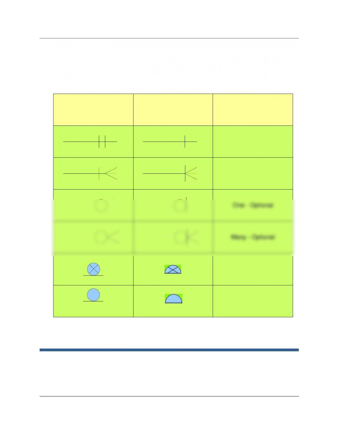
• Figure IM 4-1 on the next page summarizes the differences between the notation
used in the text and the notation used by erwin.
• Note that erwin does not display minimum cardinalities or nonidentifying relationships
on N:M diagrams, nor does it distinguish between ID-dependent and non–ID–
dependent weak entities. These must be indicated with a text note.
ERWin Symbol Meaning
One – Mandatory
Many – Mandatory
One – Optional
Many – Optional
Symbol Used In
Database Concepts
Exclusive Subtype
Inclusive Subtype
Chapter Four – Data Modeling and the Entity-Relationship Model
Page 8 of 52
• Oracle MySQL Workbench CE is free and part of the MySQL download package
(see Appendix C). NOTE: If you are using the Windows operating system, download
and use only the MySQL Installer for Windows, available at:
http://dev.mysql.com/tech-resources/articles/mysql-installer-for-windows.html
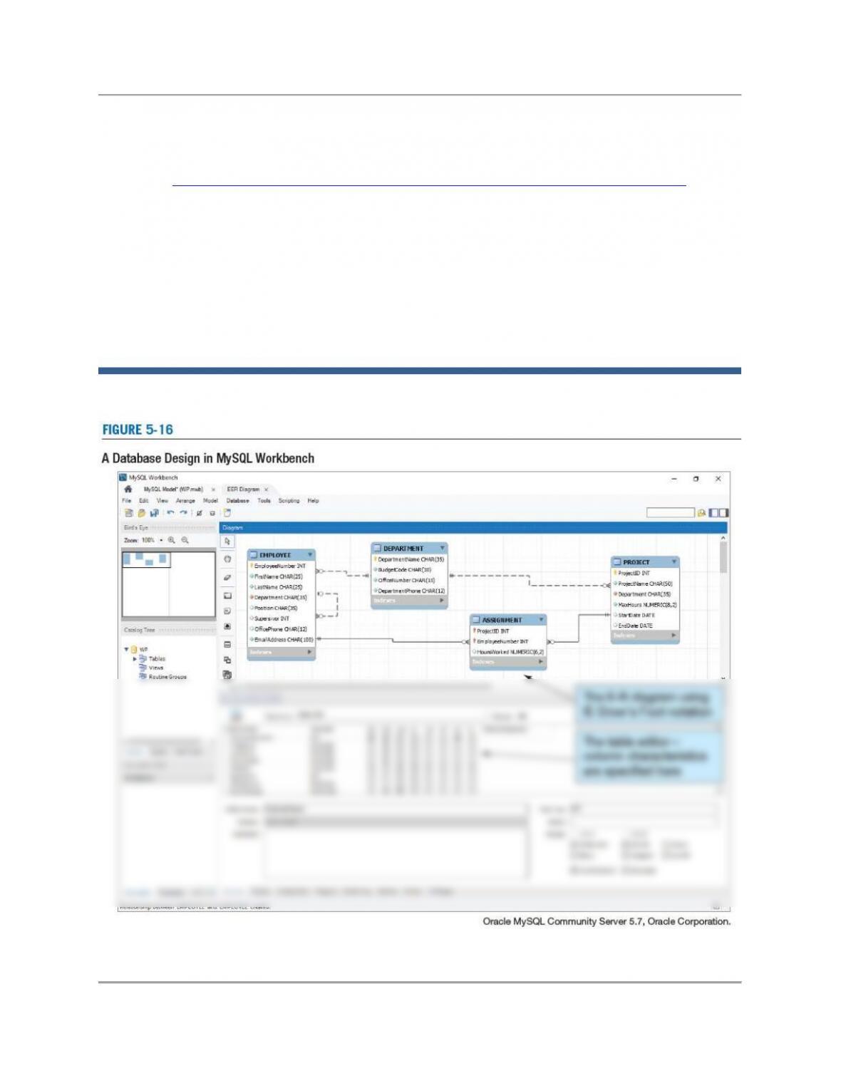
• MySQL Workbench does very nice IE Crow’s Foot database designs as shown in
Figure IM 4-2 below. (This is the same screenshot shown in the book as Figure 5-
16).
• For a complete introduction to creating data models and database designs in the
MySQL Workbench, see Appendix C, Getting Started with MySQL 5.7 Community
Server Edition. We strongly recommend having your students download and work
through this appendix if you are using MySQL Workbench in your class.
Figure IM 4-2—MySQL Workbench

Chapter Four – Data Modeling and the Entity-Relationship Model
Page 9 of 52
• Microsoft Visio 2016 is one of the software programs included in the set of software
available through the Microsoft DreamSpark program. Participation by your
department in this program will allow you to make Visio available to your students for
ANSWERS TO REVIEW QUESTIONS
4.1 Name the three stages in the process of developing database systems. Summarize the
tasks in each.
• Requirements Analysis: Users are Interviewed, sample forms, reports, queries, and
descriptions of update activities are obtained, and prototypes of working models are
developed;
4.2 What is a data model, and what is its purpose?
4.3 What is a prototype, and what is its purpose?
4.4 What is a use case, and what is its purpose?
4.5 Give an example of a data constraint.

Chapter Four – Data Modeling and the Entity-Relationship Model
Page 10 of 52
4.6 Give an example of a business rule that would need to be documented in a database
development project.
4.7 Define the term entity and give an example other than those used in this book.
4.8 Explain the difference between an entity class and an entity instance.
4.9 Define the term attribute and give examples for the entity you described in question 4.7.
4.10 Define the term identifier, and indicate which attribute defined in your answer to
question 4.9 identifies the entity.
4.11 Define the term composite identifier and give an example other than those used in this
book.
4.12 Define the term relationship and give an example other than those used in this book.
Chapter Four – Data Modeling and the Entity-Relationship Model
Page 11 of 52
4.13 Explain the difference between a relationship class and a relationship instance.
4.14 Define the term degree of relationship. Give an example, other than one used in this
text, of a relationship greater than degree two.
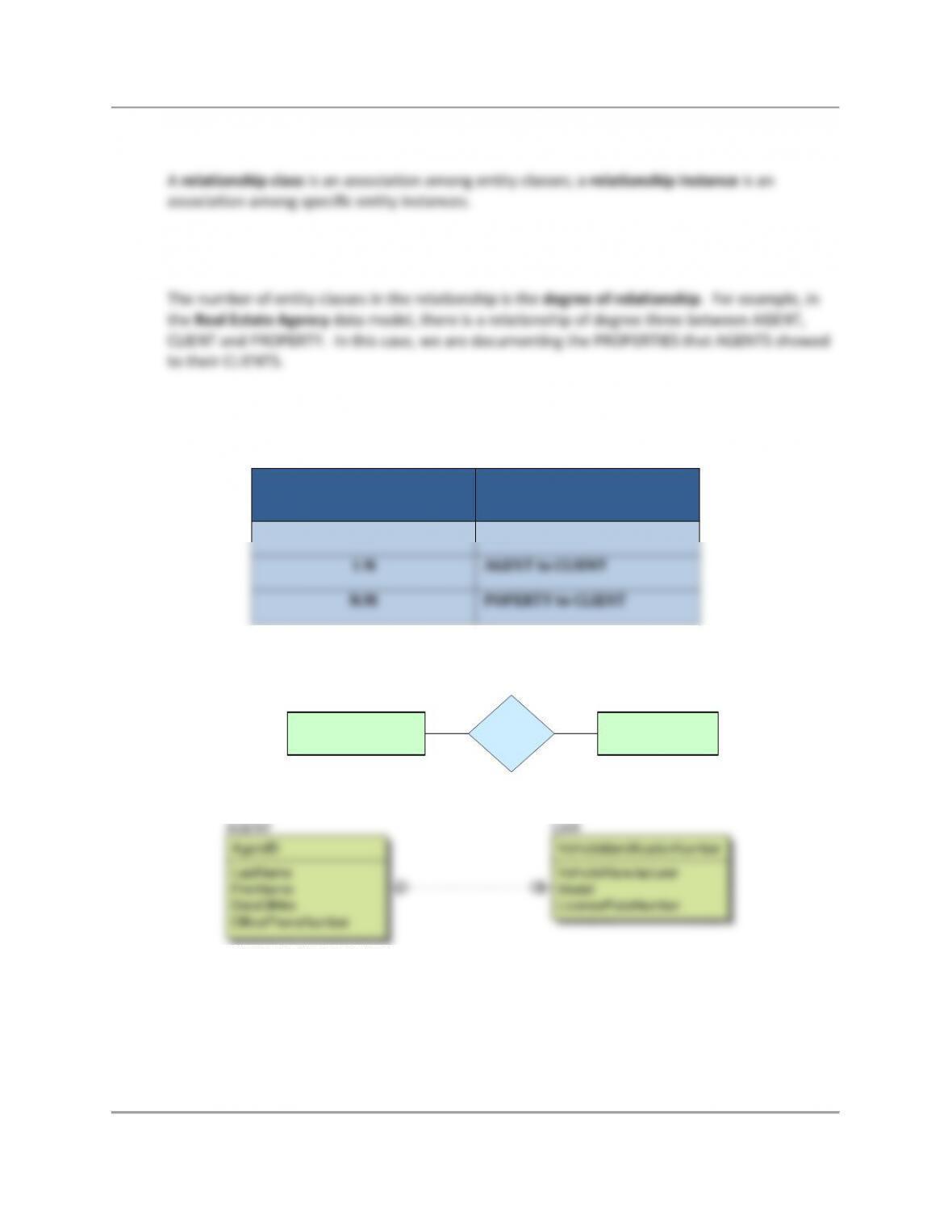
4.15 List and give an example of the three types of binary relationships other than the ones
used in this book. Draw both a traditional E-R diagram and an IE Crow’s Foot E–R
diagram for each.
TYPE of BINARY
RELATIONSHIP
EXAMPLE
1:1
AGENT to CAR
1:N
AGENT to CLIENT
N:M
POPERTY to CLIENT
1:1—AGENT to CAR:
AGENT CAR1:1
AGENT_VEHICLE
CAR
VehicleIdentificationNumber
VehicleManufacturer
Model
LicensePlateNumber
AGENT
AgentID
LastName
FirstName
DateOfHire
OfficePhoneNumber
Chapter Four – Data Modeling and the Entity-Relationship Model
Page 12 of 52
1:N—AGENT to CLIENT:
AGENT CLIENT1:N
AGENT_CLIENT
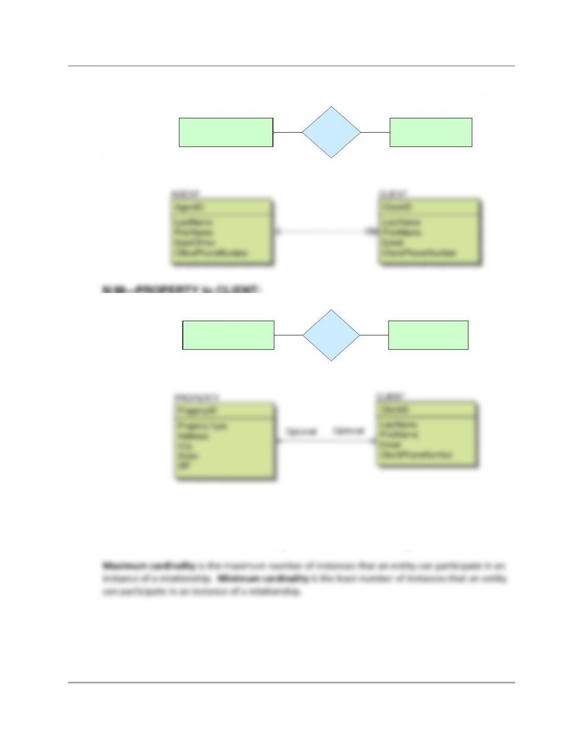
N:M—PROPERTY to CLIENT:
PROPERTY CLIENTN:M
PROPERTY_CLIENT
Note that erwin always includes cardinalities, but does not display minimum cardinalities for
N:M diagrams. For erwin N:M diagrams, minimum cardinalities must be specified by text notes.
4.16 Define the terms maximum cardinality and minimum cardinality.
AGENT
AgentID
LastName
FirstName
DateOfHire
OfficePhoneNumber
CLIENT
ClientID
LastName
FirstName
Email
ClientPhoneNumber
Optional
Optional
PROPERTY
PropertyID
PropertyType
Address
City
State
ZIP
CLIENT
ClientID
LastName
FirstName
Email
ClientPhoneNumber
Chapter Four – Data Modeling and the Entity-Relationship Model
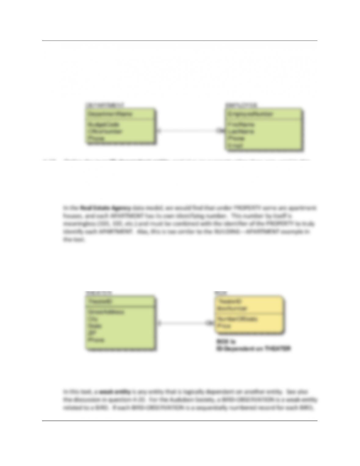
4.17 Draw an IE Crow’s Foot E-R diagram for the entities DEPARTMENT and EMPLOYEE
and the 1:N relationship between them. Assume that a DEPARTMENT does not need to
have an EMPLOYEE, but that every EMPLOYEE is assigned to a DEPARTMENT.
Include appropriate identifiers and attributes for each entity.
4.18 Define the term ID-dependent entity and give an example other than one used in this
text. Draw an IE Crow’s Foot E-R diagram for your example.
An ID-dependent entity is one in which the identifier of one entity includes the identifier of
another entity.
So, another example—a THEATER has BOXes, which are special seating sections. The number of
each BOX is meaningless (e.g., “Here’s your ticket to Box 303”) without knowing which THEATER
the BOX is in. Note that not all THEATERs have BOXes, therefore the relationship is M:O. (Note
that light yellow indicates a weak entity, whether or not ID-dependent.)
4.19 Define the term weak entity and give an example other than the one used in this text.
Draw an IE Crow’s Foot E-R diagram for your example.
EMPLOYEE
EmployeeNumber
FirstName
LastName
Phone
Email
DEPARTMENT
DepartmentName
BudgetCode
OfficeNumber
Phone
BOX is
ID-Dependent on THEATER
BOX
TheaterID
BoxNumber
NumberOfSeats
Price
THEATER
TheaterID
StreetAddress
City
State
ZIP
Phone
Chapter Four – Data Modeling and the Entity-Relationship Model
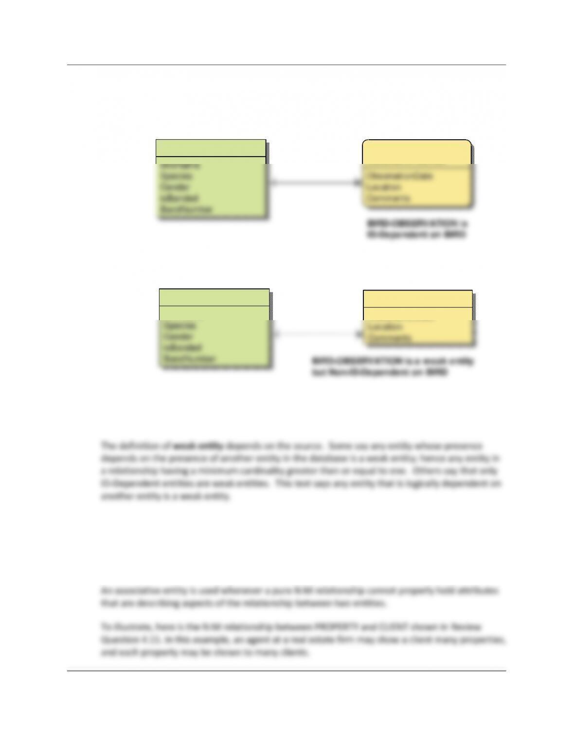
we will have another ID-dependent relationship. However, if BIRD-OBSERVATION has its own
unique identifier, then we will have a non-ID-Dependent weak entity relationship. E-R diagrams
for both versions are shown.
4.20 Explain the ambiguity in the definition of the term weak entity. Explain how this book
interprets this term.
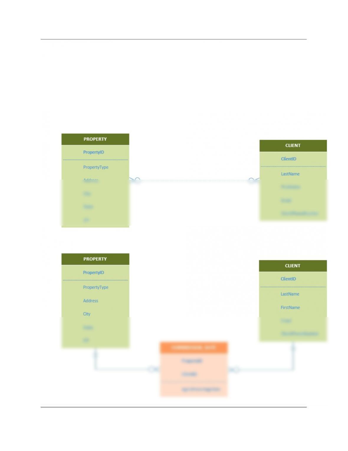
4.21 Define the term associative entity, and give an example other than one used in this text.
Your example should start with a N:M relationship between two strong entities, and then
be modified by an additional data requirement. Draw IE Crow’s Foot E-R diagrams for
both your N:M relationship, and for the relationships between the three entities that
include the associative entity.
BIRD–OBSERVATION is a weak entity
but Non-ID-Dependent on BIRD
BIRD–OBSERVATION is
ID-Dependent on BIRD
BIRD-OBSERVATION
BirdID
ObservationNumber
ObservationDate
Location
Comments
BIRD
BirdID
BirdName
Species
Gender
isBanded
BandNumber
BIRD
BirdID
BirdName
Species
Gender
isBanded
BandNumber
BIRD-OBSERVATION
ObservationID
ObservationDate
Location
Comments
Chapter Four – Data Modeling and the Entity-Relationship Model
Page 15 of 52
However, suppose that the agent’s commission percentage (if the property shown is actually
sold to the client) is a variable, and changes depending upon which client is seeing which
property. For example, if client Sam sees and buys property 01, then agent Mary gets a 6%
commission, but if client Sam sees and buys property 02, then she gets a 10% commission. Note
that these commission percentages are set based on CLIENT and PROPERTY, not on AGENT!
Clearly the AgentPercentageRate attribute cannot go in either CLIENT or PROPERTY, and
therefore an associate entity is needed to hold the attribute.
N:M—PROPERTY to CLIENT:
Associative Entity—PROPERTY to CLIENT with COMMISSION_RATE:
Chapter Four – Data Modeling and the Entity-Relationship Model
Page 16 of 52
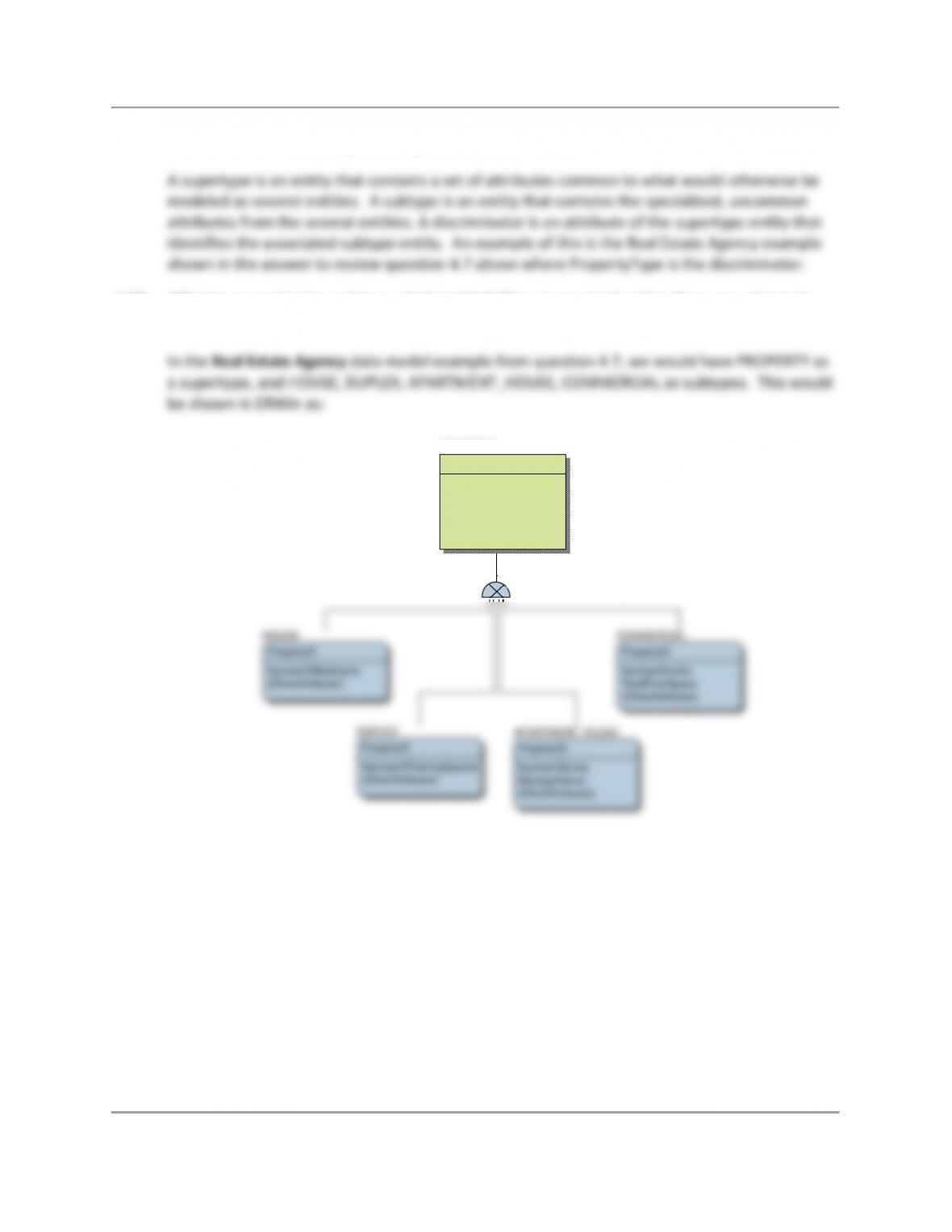
4.22 Define the terms supertype, subtype, and discriminator.
4.23 What is an exclusive subtype relationship? Give an example other than one shown in
this book. Draw an IE Crow’s Foot E-R diagram for your example.
Chapter Four – Data Modeling and the Entity-Relationship Model
Page 17 of 52
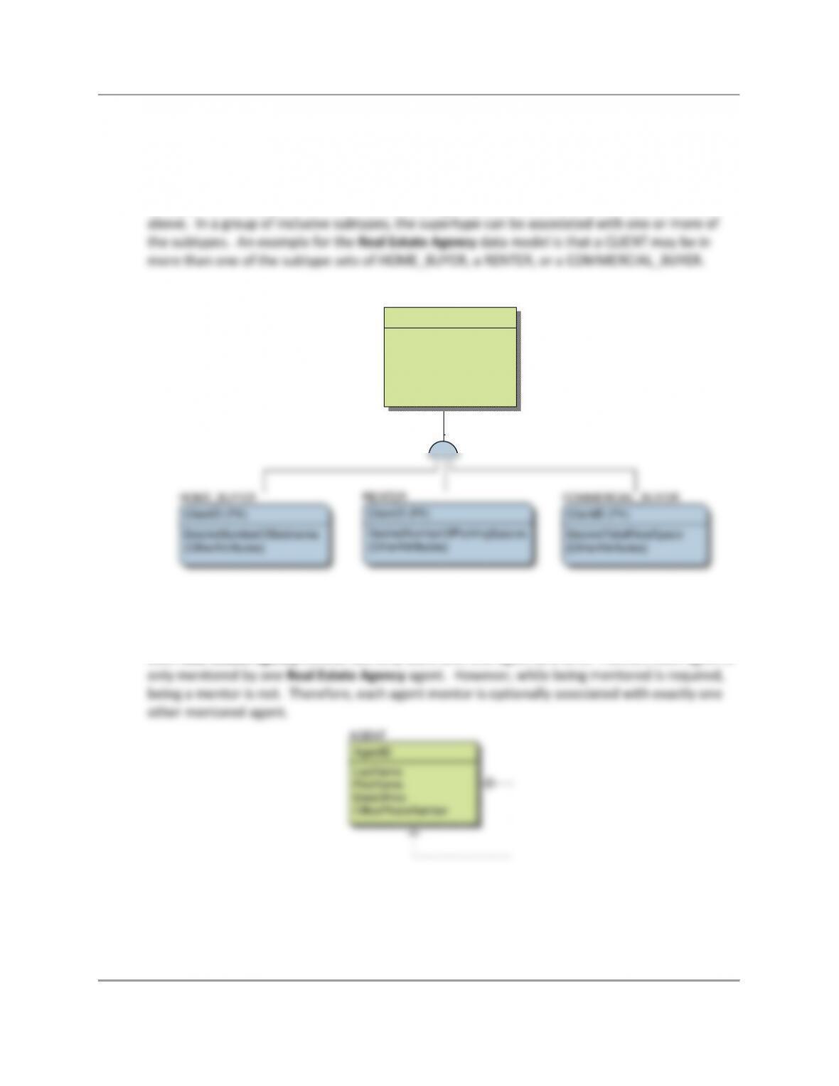
4.24 What is an inclusive subtype relationship? Give an example other than one shown in
this chapter. Draw an IE Crow’s Foot E-R diagram for your example.
A group of subtypes may be considered as either a set of exclusive subtypes or inclusive
subtypes. In a group of exclusive subtypes, the supertype is associated with at most one
subtype. An example of this is the Real Estate Agency data model as shown in question 4.22
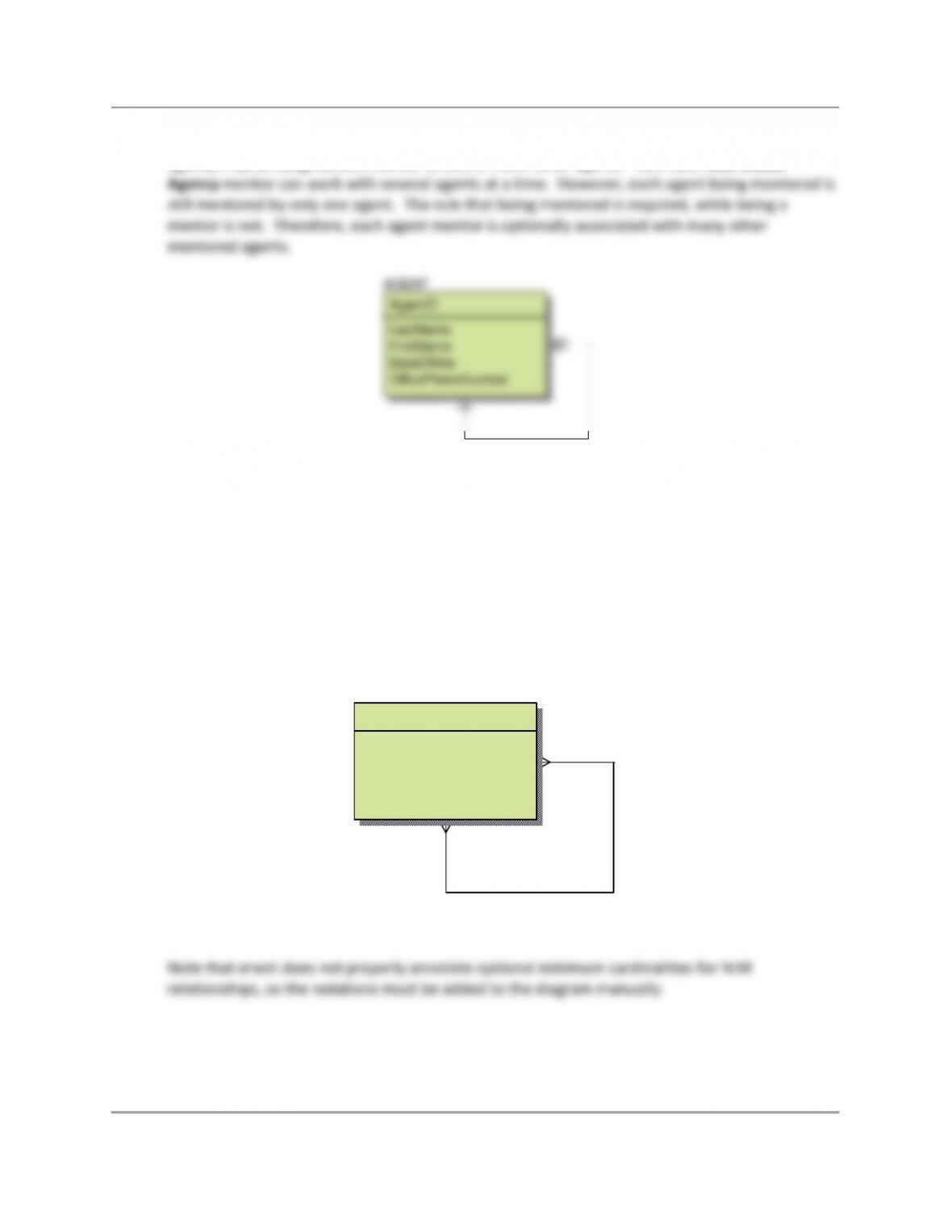
4.25 Give an example of a recursive relationship other than the one shown in this chapter.
Draw an IE Crow’s Foot E-R diagram for your example.
1:1 Recursive: Agents at the Real Estate Agency are assigned as a mentor to one other agent.
Each Real Estate Agency mentor can only work with one agent at a time. Further, each agent is
AGENT
AgentID
LastName
FirstName
DateOfHire
OfficePhoneNumber
Chapter Four – Data Modeling and the Entity-Relationship Model
Page 18 of 52
1:N Recursive: The Real Estate Agency has changed the rules about mentoring. Agents at the
agency may be assigned as a mentor to one or more other agents. Now each Real Estate
N:M Recursive: If agents in the community where the Real Estate Agency is located want to
acquire property themselves, they are required to use another agent (not necessarily at the
same agency) to act as the selling agent on the deal. If an agent makes several purchases, he or
she can use a different selling agent for each deal. Further, that agent may be the selling agent
in other deals. However, no agent is required to buy property, so working with a selling agent is
optional. Similarly, no agent is required to be the selling agent in this type of a transaction.
Therefore, each agent is optionally associated with many other selling agents, and may
optionally be a selling agent to many other agents.
AGENT
AgentID
LastName
FirstName
DateOfHire
OfficePhoneNumber
Optional
Optional
AGENT
AgentID
LastName
FirstName
DateOfHire
OfficePhoneNumber

Chapter Four – Data Modeling and the Entity-Relationship Model
Page 19 of 52
4.26 Give an example of a business rule for your work for question 4.17.
4.27 Describe why it is important to evaluate a data model.
4.28 Summarize one technique for evaluating a data model, and explain how that technique
could be used to evaluate the data model in Figure 4-21[c].
ANSWERS TO EXERCISES
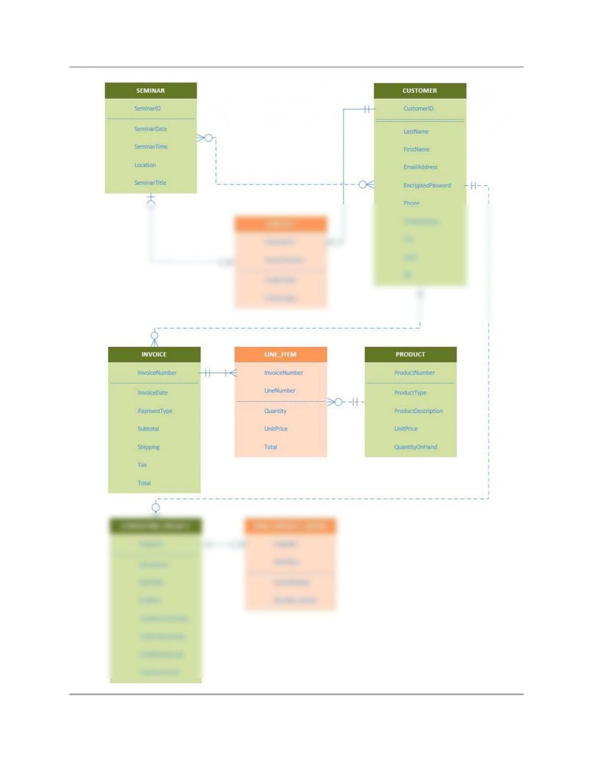
4.29 Suppose that Heather Sweeney wants to include records of her consulting services in
her database. Extend the data model in Figure 4-21(c) to include
CONSULTING_PROJECT and DAILY_PROJECT_HOURS entities.
CONSULTING_PROJECT contains data about a particular project for one of Heather’s
customers, and DAILY_PROJECT_HOURS contains data about the hours spent and a
description of the work accomplished on a particular day for a particular project. Use
strong and/or weak entities as appropriate. Specify minimum and maximum
cardinalities. Use the IE Crow’s Foot E-R model for your E-R diagrams.
Chapter Four – Data Modeling and the Entity-Relationship Model
Page 20 of 52