– Part III
Chapter 17 Methodology – Logical Database Design for Relational Model
Review Questions
17.1 Discuss the purpose of logical database design.
17.2 Describe the rules for deriving relations that represent:
(a) strong entity types;
(b) weak entity types;
17.3 Discuss how the technique of normalization can be used to validate the relations derived from
the conceptual data model.
The logical data model can be validated using the technique of nomalization and against the
17.4 Discuss two approaches that can be used to validate that the relational schema is capable of
supporting the required transactions.
Two possible approaches to ensure that the logical data model supports the required
17.5 Describe the purpose of integrity constraints and identify the main types of constraints on a
logical data model.
– Part III
14
17.6 Describe the alternative strategies that can be applied if there exists a child occurrence
referencing a parent occurrence that we wish to delete.
17.7 Identify the tasks typically associated with merging local logical data models into a global
logical model.
Exercises
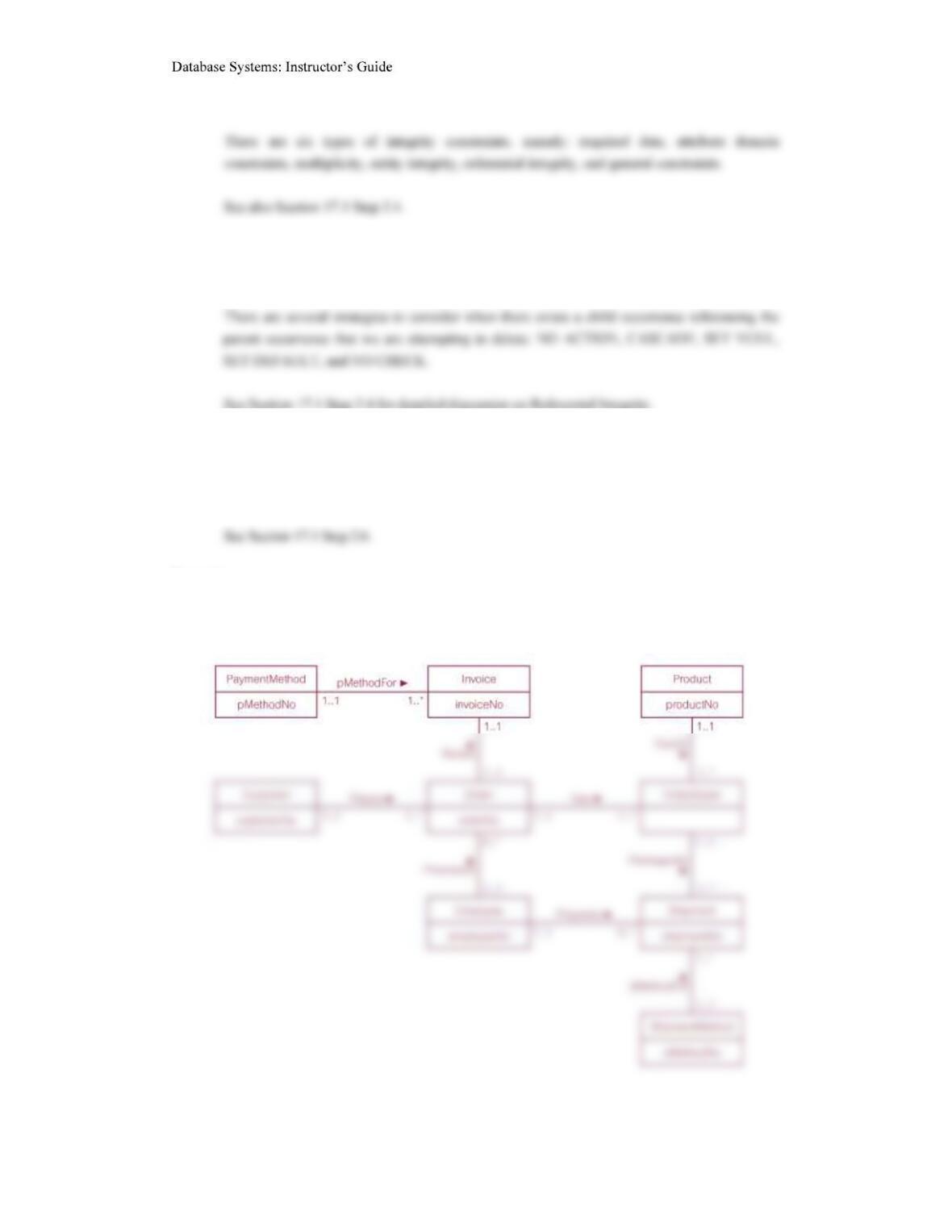
17.8 Derive relations for the following conceptual data model:
– Part III
15
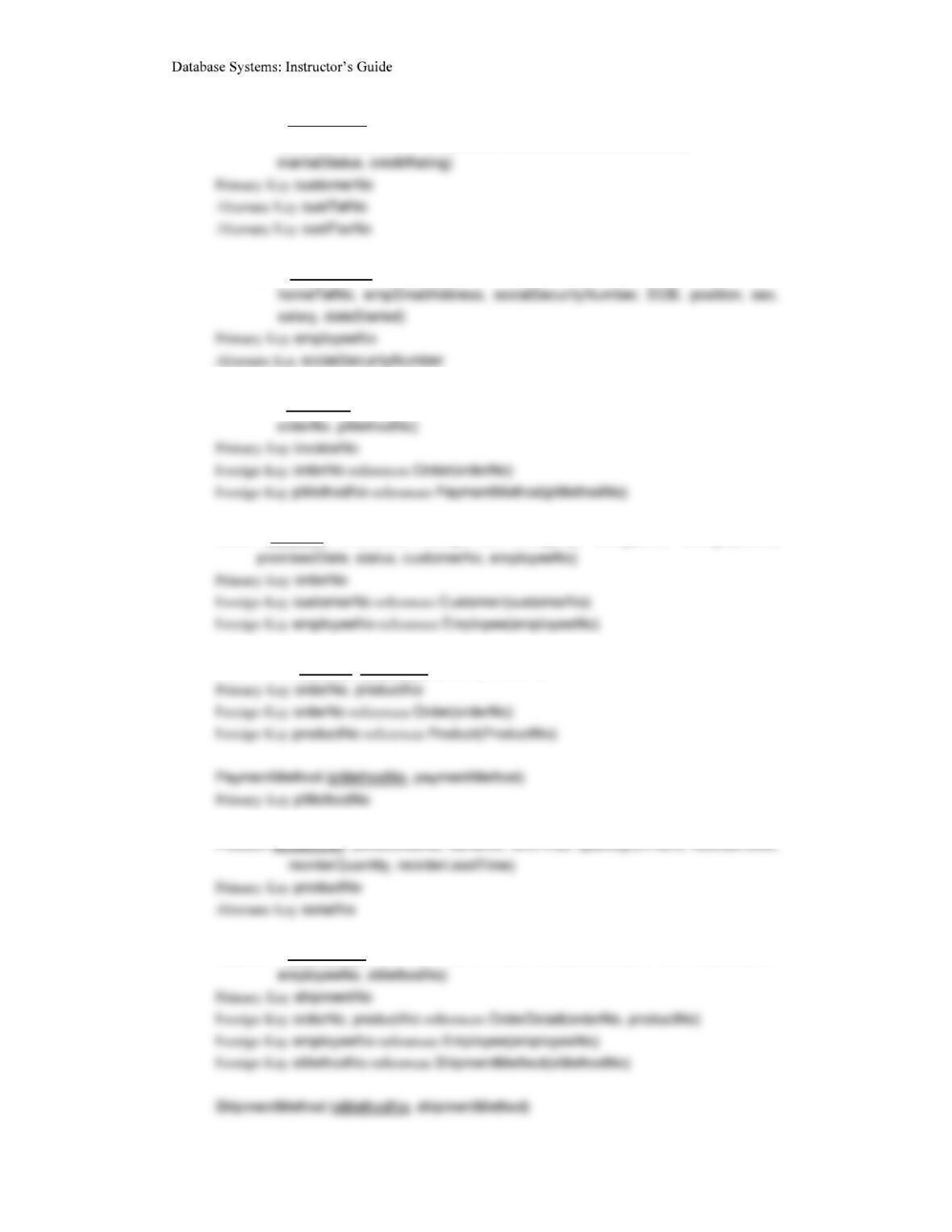
Customer (customerNo, customerName, customerStreet, customerCity,
customerState, customerZipCode, custTelNo, custFaxNo, DOB,
Employee (employeeNo, title, firstName, middleName, lastName, address, workTelExt,
Invoice (invoiceNo, dateRaised, datePaid, creditCardNo, holdersName, expiryDate,
Order (orderNo, orderDate, billingStreet, billingCity, billingState, billingZipCode,
OrderDetail (orderNo, productNo, quantityOrdered)
Product (productNo, productName, serialNo, unitPrice, quantityOnHand, reorderLevel,
Shipment (shipmentNo, quantity, shipmentDate, completeStatus, orderNo, productNo,
– Part III
16
The DreamHome case study
17.9 Create a relational schema for the Branch view of DreamHome based on the conceptual data
model produced in Exercise 15.13 and compare your schema with the relations listed in
Figure 16.5. Justify any differences found.
The University Accommodation Office case study
17.10 Create and validate a logical data model from the local conceptual data model for the
University Accommodation Office case study created in Exercise 15.16.
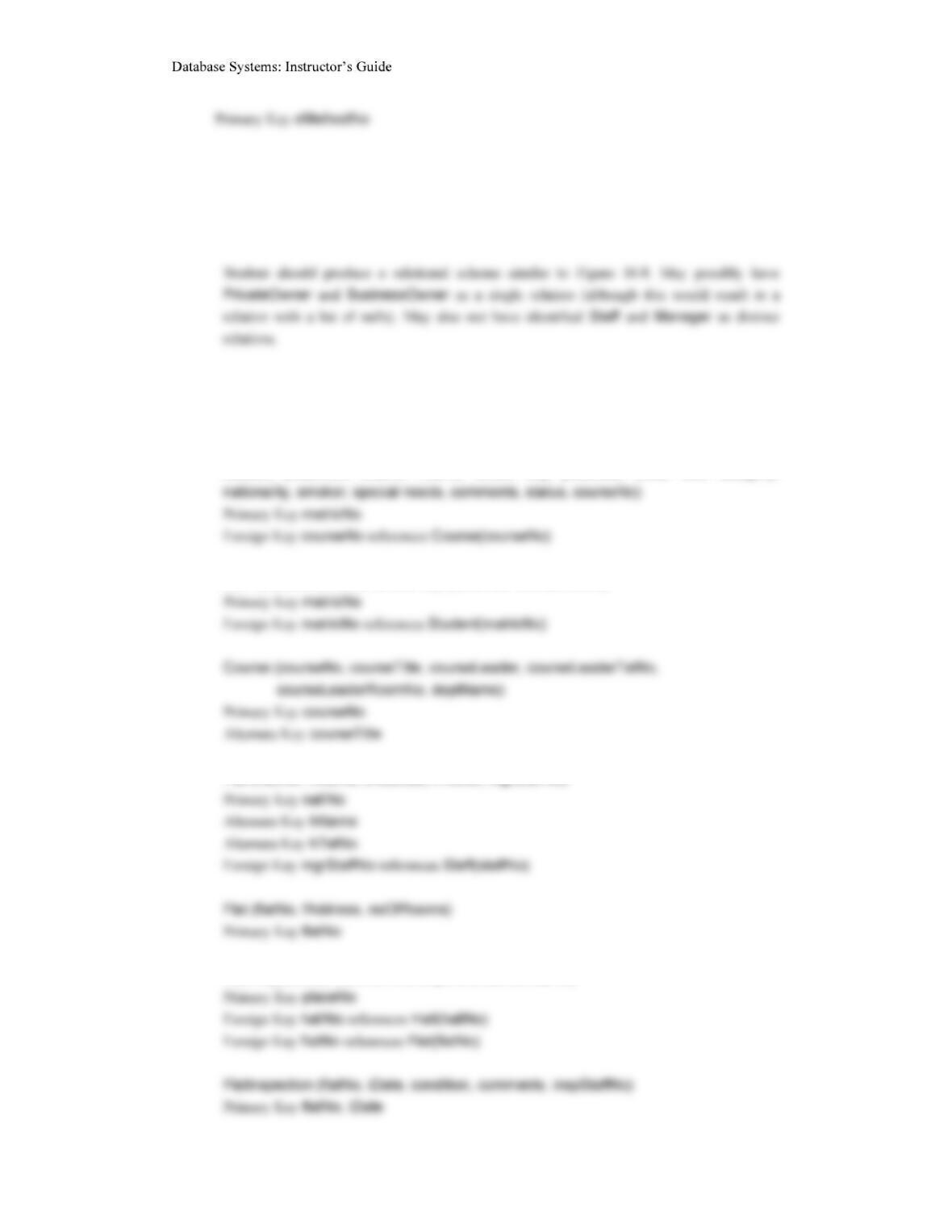
Student (matricNo, fName, lName, street, city, postcode, DOB, sex, category,
NOK (matricNo, name, street, city, postcode, contactTelNo)
Hall (halINo, hName, hAddress, hTeINo, mgrStaffNo)
Room (placeNo, roomNo, monthlyRent, flatNo, hallNo)
– Part III
17
Lease (leaseNo, duration, matricNo, placeNo, dateEnter, dateLeave)
The EasyDrive School of Motoring case study
17.11 Create and validate a local logical data model from the conceptual data model for the
EasyDrive School of Motoring case study created in Exercise 15.18.
Office (officeNo, oAddress, oPostcode, oTelNo, oFaxNo, mgrStaffNo)
Primary Key officeNo
– Part III
18
Primary Key clientNo
Lesson(lessonNo, lessonDate, lessonTime, stage, progress, comments,
DrivingTest(testNo, testDate, testTime, testCentre, testerName, attempt, result,
pTestComment, tTestMark, tTestComments, clientNo, vehRegNo)
The Wellmeadows Hospital case study
17.13 Create and validate the local logical data models for each of the local conceptual data models
of the Wellmeadows Hospital case study identified in Exercise 14.21.
17.13 Merge the local data models to create a global logical data model of the Wellmeadows
Hospital case study. State any assumptions necessary to support your design.
Once the local data models have been validated, the student should demonstrate the view
integration approach to create a global logical data model. The student should produce an ER
– Part III
19
Ward (wardNo, wardName, location, totalBeds, telExtn, chargeNurseStaffNo)
Staff (staffNo, fName, lName, address, telNo, DOB, sex, NIN, position, salary, sScale,
Qualification (staffNo, oType, oDate, institutionName)
WorkExperience (staffNo, sDate, fDate, position, orgName)
Patient (patNo, fName, lName, address, telNo, DOB, sex, mStatus, dateReg,
docName, clinicNo, nokName, nokRelationship, nokAddress, nokTelNo)
– Part III
20
Primary Key patNo, outPatDate
InPatientAllocation (patNo, listDate, wardReq, duration, placedDate, exLeaveDate,
ON DELETE NO ACTION ON UPDATE CASCADE
Medication (patNo, drugNo, unitsDay, aMethod, sDate, fDate)
Non-Surgical/Surgical (itemNo, iName, iDescription, quantityStock, reorderLevel,
Requisition (reqNo, chargeNurseStaffNo, wardNo, itemdrugNo, quantReq, dateOrder,
dateReceive)
– Part III
21
Supplier (supplierNo, sName, sAddress, telNo, faxNo)
The Parking Lot case study
17.14 Present the relational schema mapped from the Parking Lot EER model shown in Figure
Staff(staffNo, fName, lName extensionTelNo)
Primary Key staffNo
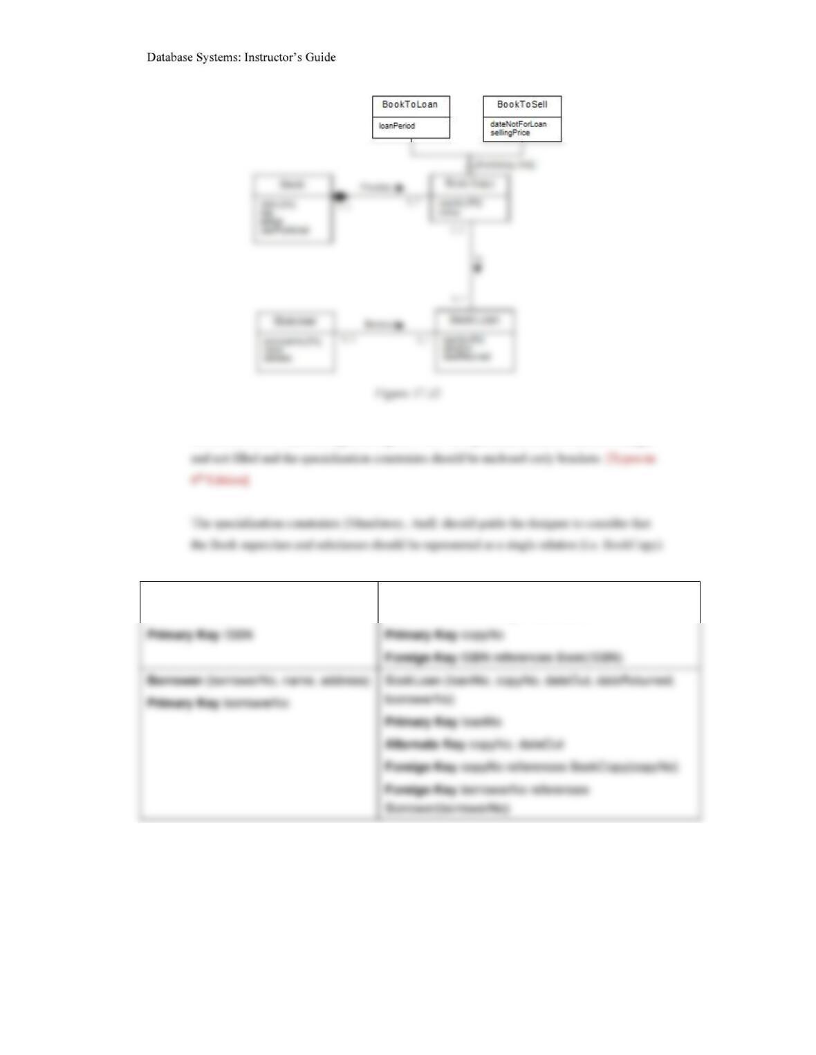
The Library case study
17.15 Describethe relational schema mapped from the Library EER model shown in Figure 17.12
and described in Exercises 12.14 and 13.12.
– Part III
22
Note in the book – there are typos in Figure 17.12 – the specialization arrow should be larger
Book (ISBN, title, edition,
yearPublished)
BookCopy (copyNo, status, loanPeriod,
dateNotForLoan, sellingPrice, ISBN)
17.16 Describethe relational schema mapped from the Library EER model shown in Figure 17.12
and described in Exercises 12.14 and 13.12.
– Part III
23
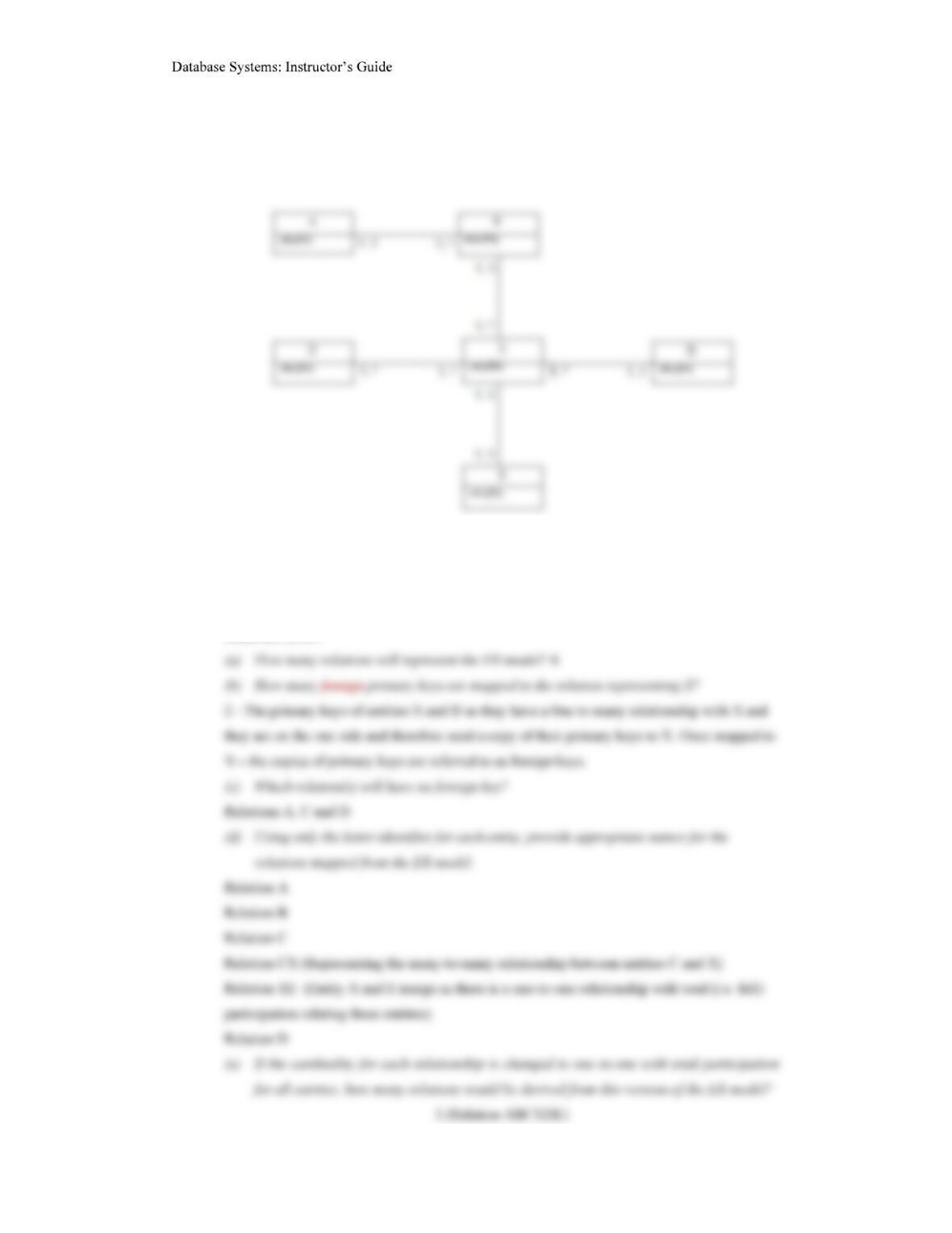
17.16 The ER diagram in Figure 17.13 shows only entities and primary key attributes. The absence
of recognisable named entities or relationships is to emphasize the rule-based nature of the
mapping rules described in Step 2.1 of logical database design.
Figure 17.13
Answer the following questions with reference to how the ER model in Figure 17.13 maps to
relational tables.