
INSTRUCTOR’S MANUAL
TO ACCOMPANY
40th Anniversary Edition
DATABASE PROCESSING
Fundamentals, Design, and Implementation
15th Edition
Appendix C
E-R Diagrams and the IDEF1X and UML Standards
David M. Kroenke | David J. Auer | Scott L. Vandenberg | Robert C. Yoder

Appendix C – E-R Diagrams and the IDEF1X and UML Standards
Page C-2
❖ CHAPTER OBJECTIVES
• To understand IDEF1X standard E-R diagrams
• To be able to model non-identifying connection relationships, identifying
connection relationships, nonspecific relationships, and categorization
relationships using IDEF1X E-R model
❖ ERRATA
There are no known errors at this time. Any errors that are discovered in the future will
❖ TEACHING SUGGESTIONS
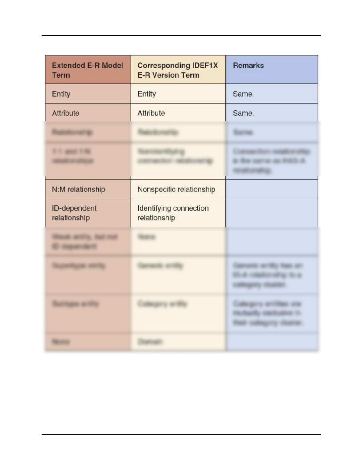
• Figure C-1 (reproduced below) provides a good transition between the enhanced
E-R model and the IDEF1X model. Use it to introduce the IDEF1X model and
compare it to the enhanced E-R model.

Appendix C – E-R Diagrams and the IDEF1X and UML Standards
Page C-3
• Note that the solutions in this IM section were created using Microsoft Visio
2016 and the IDEF1X Database Notation stencil. In the IDEDF1X stencil,
Microsoft Visio 2016 uses the following line endings, which match the notation
shown in the appendix itself:
Line End Symbol:
Meaning:
1 (parent required) [This line end must
be added manually]
Appendix C – E-R Diagrams and the IDEF1X and UML Standards
Page C-4
Figure C-1 – Correspondence of Terms between the Extended E-R Model and the
IDEF1X Version of the E-R Model

Appendix C – E-R Diagrams and the IDEF1X and UML Standards
Page C-5
❖ ANSWERS TO REVIEW QUESTIONS
C.1. Why is the IDEF1X model important?
IDEF1X became a national standard and companies that sold data modeling tools had to conform
C.2. Name four types of IDEF1X relationships.
The four types of IDEF1X relationships are (1) non-identifying connection relationship, (2)
C.3. What is a non-identifying connection relationship? How do such relationships relate to
the extended E-R model described in Chapter 5?
Non-identifying connection relationships are 1:1 or 1:N relationships between two non-ID
C.4. What is an identifying connection relationship? How do such relationships relate to the
extended E-R model described in Chapter 5?
C.5. What is a nonspecific relationship? How do such relationships relate to the extended E-
R model described in Chapter 5?
C.6. Explain the major differences between categorization relationships and
supertype/subtype relationships in the extended E-R model described in Chapter 5.
There are two major differences between categorization relationships and supertype/subtype
relationships:
Appendix C – E-R Diagrams and the IDEF1X and UML Standards
Page C-6
C.7. What are the major advantages of the modeling of domains?
A domain is a named set of values that can be assigned to an attribute. The advantages are:
(1) Domains reduce ambiguity for attributes with values that look similar but are not the same.
C.8. Why is UML important? Why is it of concern to database designers?
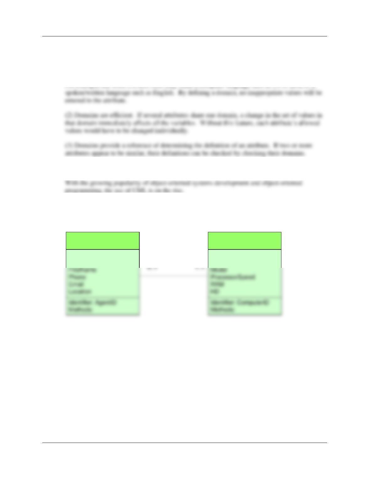
C.9. Show a 1:1 relationship in UML format.
We’ll use a Real Estate Agency database. Each agent is assigned to exactly one computer.
AGENT
AgentID
LastName
COMPUTER
ComputerID
Make
COMPUTER-
ASSIGNMENT
Appendix C – E-R Diagrams and the IDEF1X and UML Standards
Page C-7
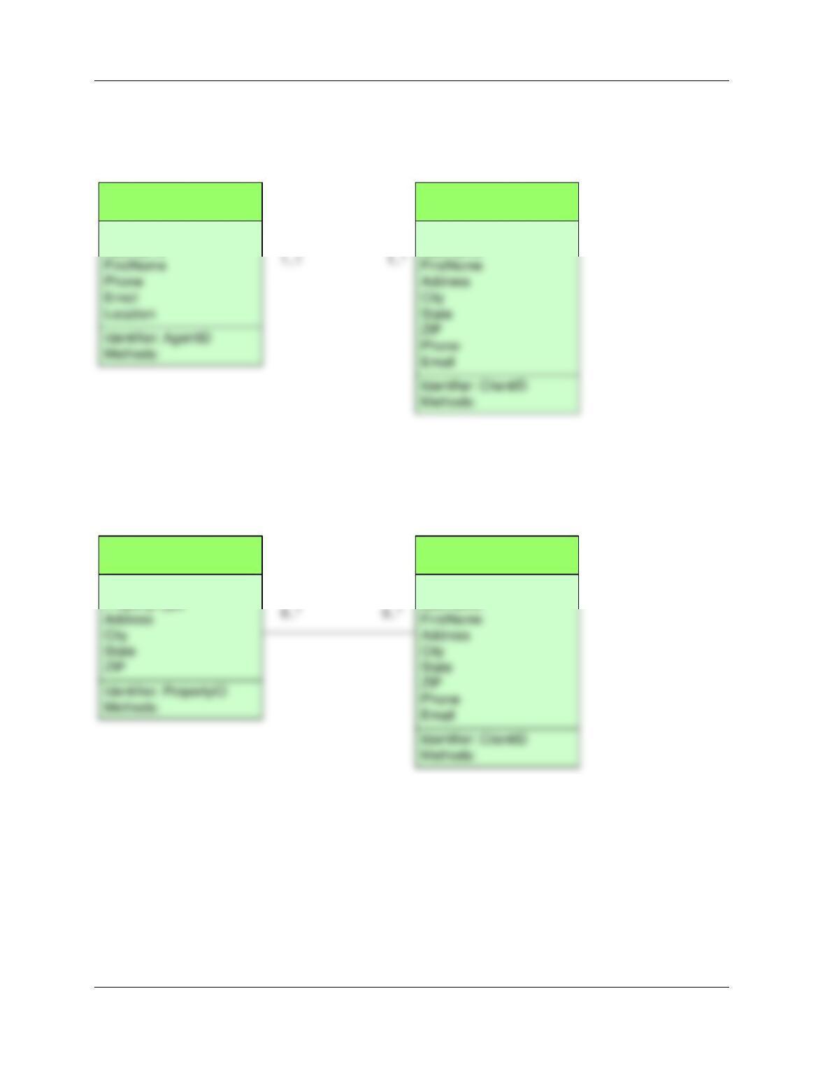
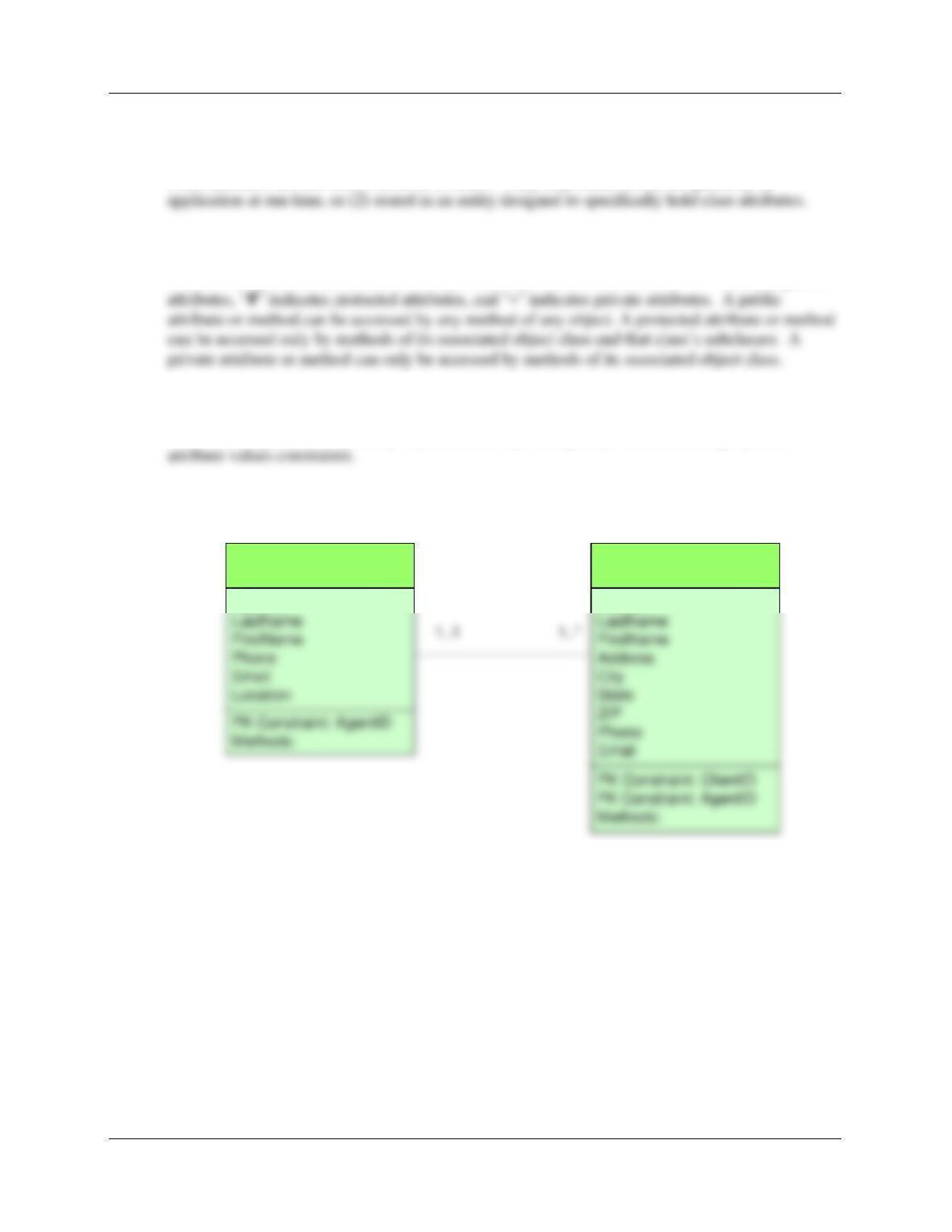
C.10. Show a 1:N relationship in UML format.
We’ll use a Real Estate Agency database. Each agent is assigned to many clients, and each client
must be assigned to exactly one agent.
AGENT
AgentID
LastName
CLIENT
ClientID
LastName
CLIENT-ASSIGNMENT
C.11. Show an N:M relationship in UML format.
We’ll use a Real Estate Agency database. Each client may be interested in many properties, and
each property may appeal to many clients.
PROPERTY
PropertyID
PropertyType
CLIENT
ClientID
LastName
CLIENT-PROPERTY
-INTEREST
C.12. Explain how UML documents minimum cardinality.
Cardinalities are represented in the format x..y. In this format, x is the minimum cardinality and y
is the maximum cardinality. If x=0, no entity is required, and if x=1, one entity is required.
Appendix C – E-R Diagrams and the IDEF1X and UML Standards
Page C-8
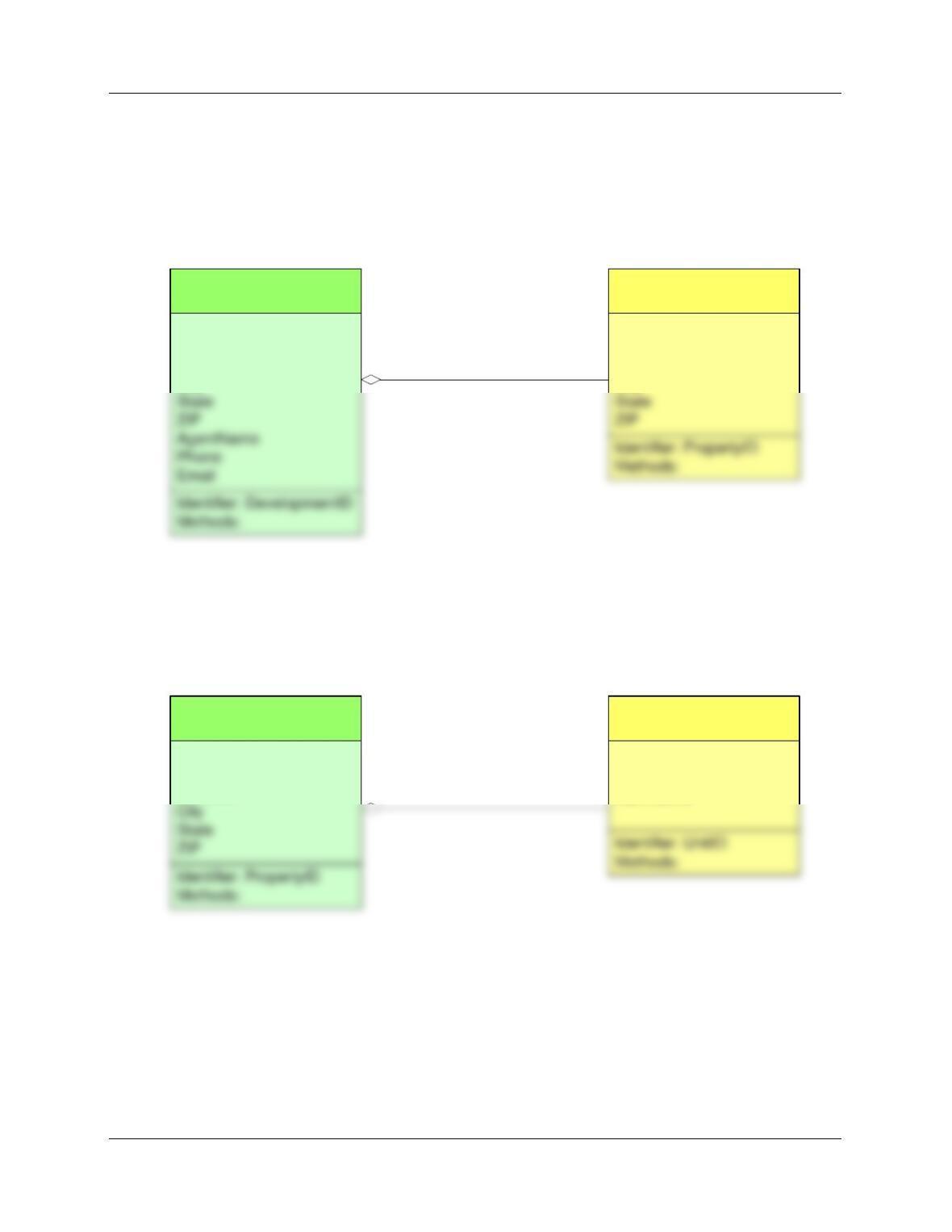
C.13. Show identifying and non-identifying weak entities in UML format.
We’ll use a Real Estate Agency database. Each development is made up of 1 or more units, each
of which has its own unique address. Therefore, the relationship is non-identifying.
NOTE: The diamond shown in the relationship should be a solid black, rather than white as
shown.
PROPERTY
PropertyID
PropertyType
Address
City
DEVELOPMENT
DevelopmentID
DevelopmentName
Location
City
DEVELOPMENT-PROPERTY
1 1..*
<nonidentifying>
We’ll use a Real Estate Agency database. Each property is made up of 1 or more units, each of
which is identified by the property address and a unit number. Therefore the units are dependent
on the property address, and the relationship is identifying.
NOTE: The diamond shown in the relationship should be a solid black, rather than white as
shown.
PROPERTY
PropertyID
PropertyType
Address
UNIT
UnitID
Bedrooms
Bathrooms
PROPERTY-UNIT
1 1..*
<identifying>
Page C-9
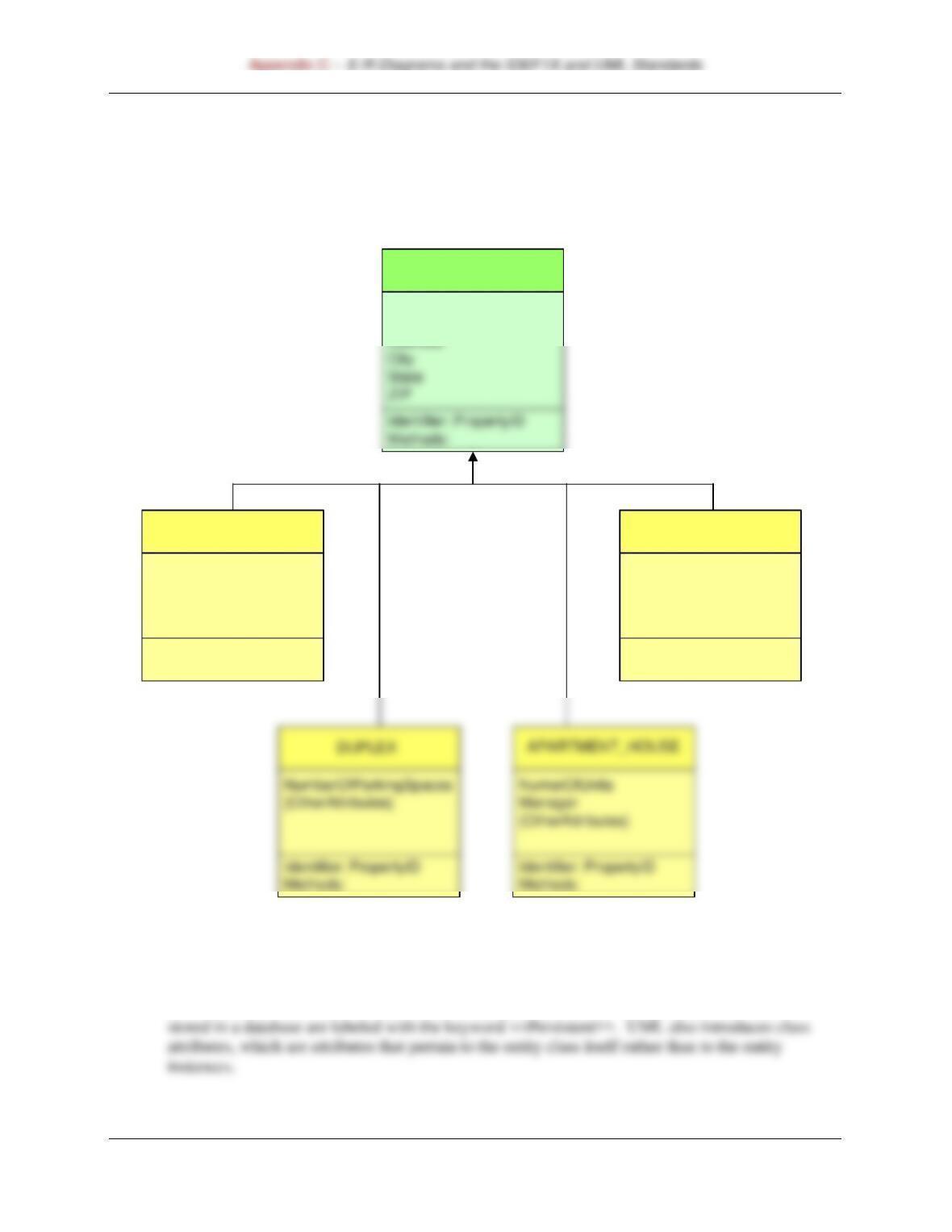
C.14. Show subtypes in UML format.
We’ll use a Real Estate Agency database. We would have PROPERTY as a supertype, and
HOUSE, DUPLEX, APARTMENT_HOUSE, COMMERCIAL as subtypes.
PROPERTY
PropertyID
PropertyType
COMMERCIAL
NumberOfUnits
TotalFloorSpace
{OtherAttributes}
PropertyType
Identifier: PropertyID
Methods:
HOUSE
NumberOfBedrooms
{Other Attributes}
Identifier: PropertyID
Methods:
C.15. What are class attributes? How are they documented in UML?
In UML, some OOP constructs are added to entity UML classes. Entity classes that will be
Appendix C – E-R Diagrams and the IDEF1X and UML Standards
Page C-10
C.16. How would class attributes be represented in the extended E-R model described in
Chapter 5?
Class attributes are not stored in the E-R model. They may either be (1) computed by an
C.17. Explain the significance of the +, #, and – signs in a UML diagram.
These three symbols indicate the visibility of attributes in the UML model. “+” indicates public
C.18. Give an example of a constraint on an entity in a UML diagram.
E-R models typically use primary key, alternate key, foreign key, referential integrity, and
The Real Estate Agency Client-Assignment 1:N relationship for review question C-10 is shown
below with primary key (PK) and foreign key (FK) constraints.
AGENT
AgentID
CLIENT
ClientID
CLIENT-ASSIGNMENT
Appendix C – E-R Diagrams and the IDEF1X and UML Standards
Page C-11
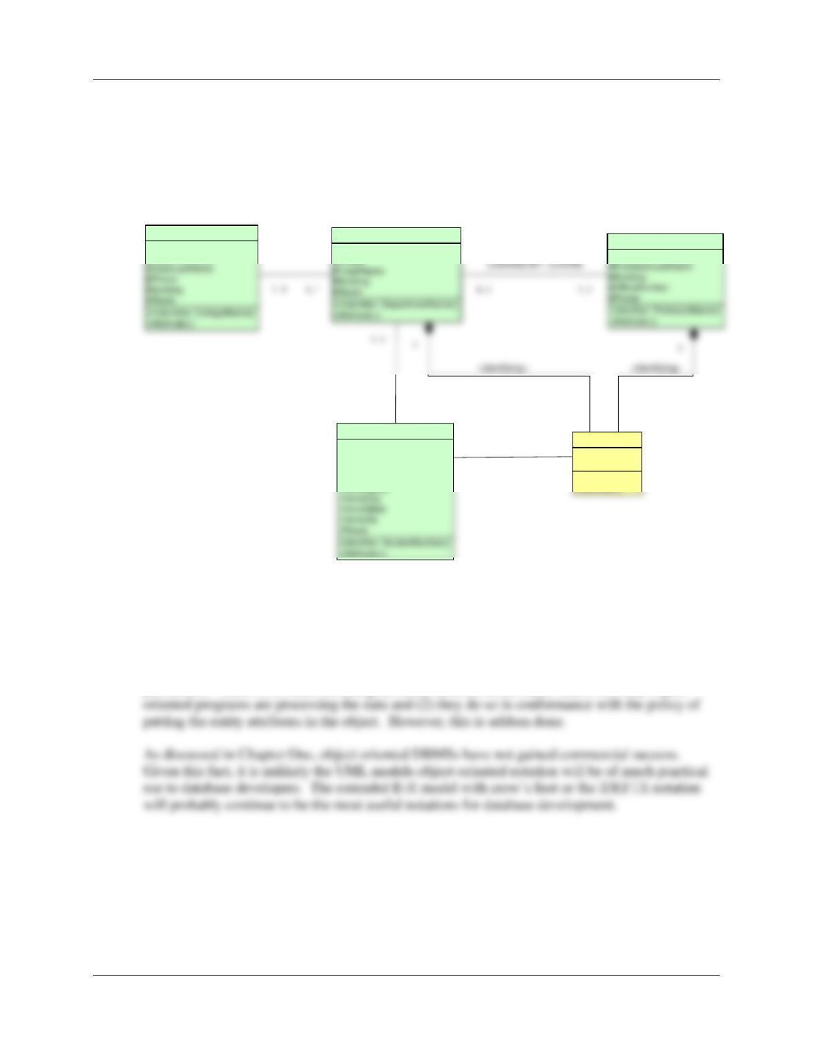
C.19 Redraw the E-R diagram in Figure 5-52 using UML.
NOTE: Microsoft Visio 2010 and Microsoft Visio 2016 both have a UML template, and the
drawings below were done using the Microsoft Visio 2010 template.
+CollegeName
#DeanFirstName
COLLEGE
+DepartmentName
#Phone
DEPARTMENT
#ProfessorFirstName
PROFESSOR
-StudentNumber
-Title
-StudentFirstName
-StudentLastName
STUDENT
0..*
+Indentifier:()
-Title
-Terms
APPOINTMENT
1..*
0..* 1..1
1..*
ADVISED BY / ADVISES
C.1. Describe the ways in which UML and commercial database processing are misfits. How
do you think this situation will be resolved?
Object-oriented notation does not fit well with today’s commercial database processing
procedures. There is no sense in hiding an entity attribute in an object unless (1) only object–