37
Exercise 8
Construction Staking
OBJECTIVE
The objective of this exercise is to demonstrate staking
and measurement techniques used to lay out projects.
TEXTBOOK REFERENCE
INTRODUCTION
Identifying the location of proposed improvements on
a site is necessary when constructing any landscape
project. Accurate layout of the elements of a landscape
design requires mastery of the techniques and methods
of construction staking. Techniques for construction
Staking Techniques
Following are step-by-step descriptions of the techniques
that can be used to accurately locate points and lines
Locating Points Using Triangulation
• Identify two known points in a landscape that
are within a short distance of the object being
located.
• Measure from each point to the object being
located (Figure 8–1A).
adjust for scale. Where the arcs intersect is the
location of the unknown point (Figure 8–1B).
This process can be reversed for locating an
object in the field.
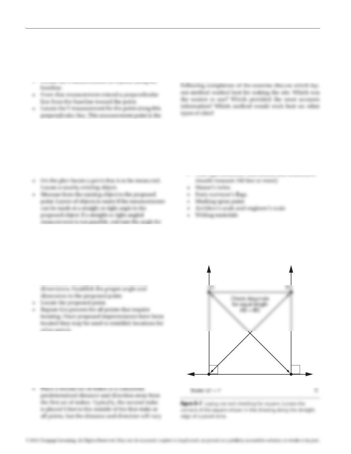
Layout of Right Angles Using 3, 4, 5 Triangle
• Locate an existing straight edge at the
project site.
• Adjust both tapes until the 4 foot mark on tape
A and the 5 foot mark on tape B intersect. Mark
directly below that point (point C, Figure 8–2).
• The line traveling from point A and passing through
point C will be at a right angle to the first edge.
97171_08_ch08_p037-043.indd 37 14/06/10 8:44 PM
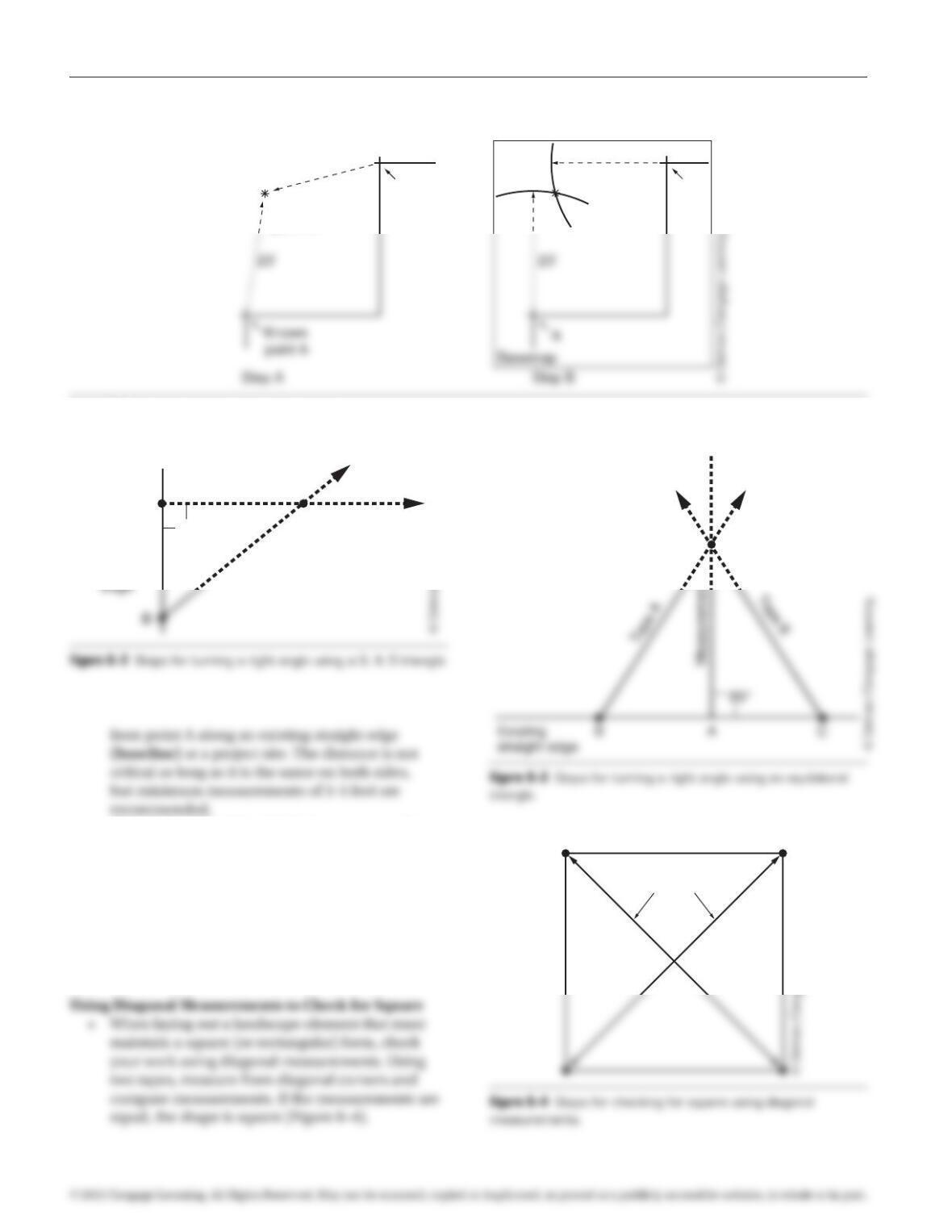
• From points B and C, stretch tape measures (tapes
A and B in Figure 8–3) in the direction of the
desired perpendicular.
• Select a measurement on tape A and match it with
the same measurement on tape B.
• Mark the point where these like measurements
intersect (point D, Figure 8–3).
• A line laid out from point A through point D will
be at a right angle to the baseline.
38 Exercise 8 Construction Staking
A. Measure the distance to unknown point from known Points A and B.
B. Draw arcs for both distance A and B. Unknown point is where arcs intersect.
Known
point B
Unknown
point C
B
C
20′
20′
Figure 8–1 Locating objects using triangulation.
Check diagonals
for equal length
Tape A
Tape B
Existing
straight
90°
A
C
lineMeasurement
D
97171_08_ch08_p037-043.indd 38 14/06/10 8:44 PM
• If one measurement is longer than the other,
the long corner must be pushed in slightly and
the short corner pulled out slightly until the
measurements match.
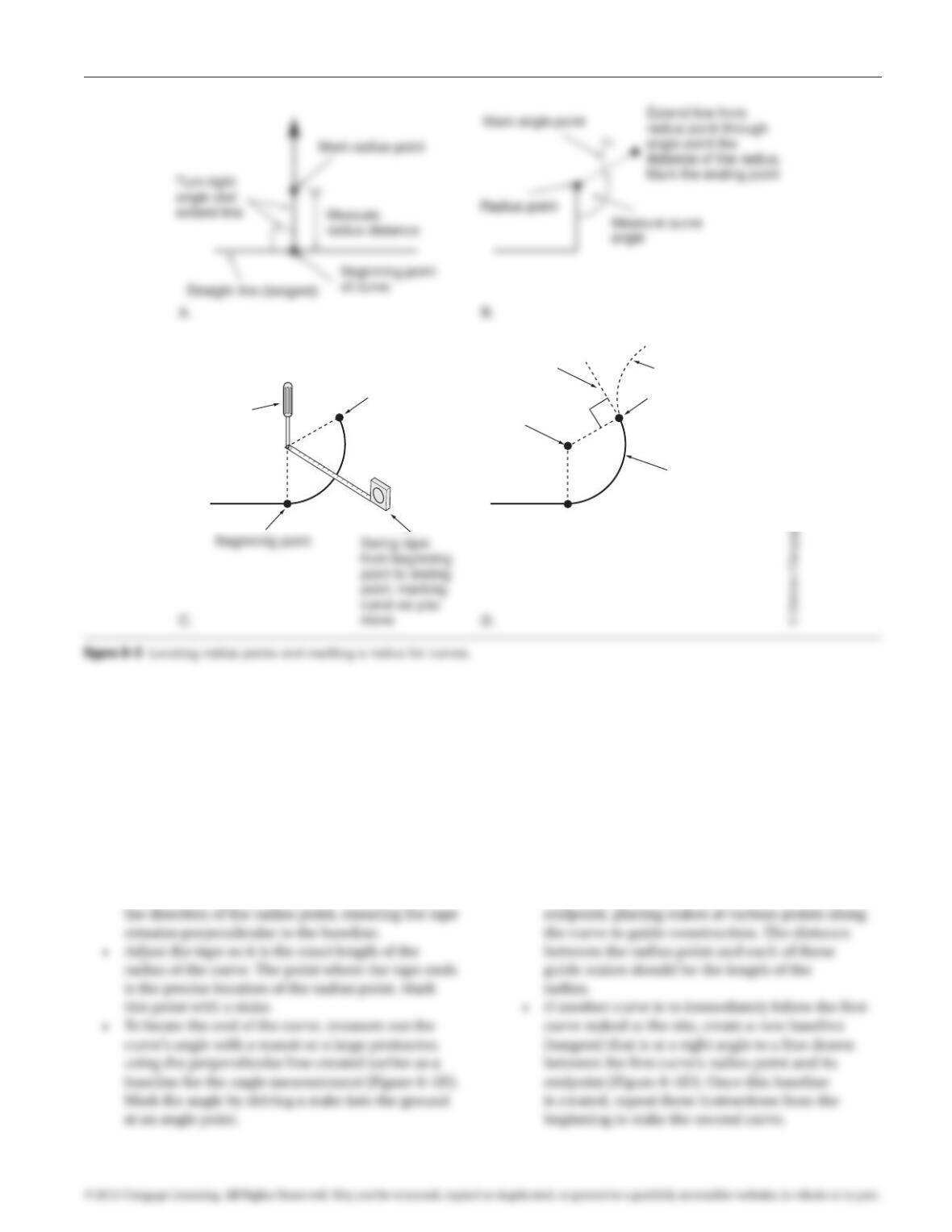
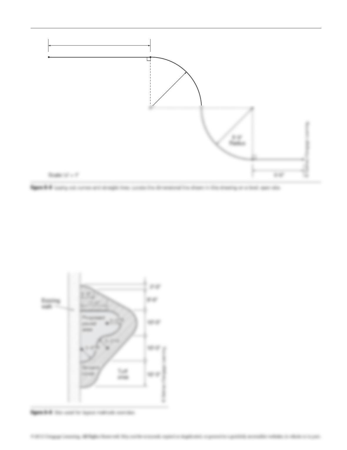
Locating Radius Points and Marking Curves
• Locate the point where the curve is to
begin along a baseline at the site (tangent)
(Figure 8–5A). Identify the general location
of the radius point of the curve.
• Extend a tape measure from the baseline point in
• Extend a tape measure from the radius point in the
direction of the endpoint. The tape should pass
through the angle point.
• Adjust the tape so it is the exact length of the
radius of the curve. The point where the tape ends
is the precise location of the endpoint. Mark this
point with a stake.
• Anchor the tape measure at the radius point
with a screwdriver and pull the tape taut
(Figure 8–5C). Swing the tape from the
beginning point of the curve to the curve’s
Exercise 8 Construction Staking 39
Ending point
Ending point
New curve would
begin at ending point
Radius
point
Curve
Anchor tape
measure at
radius point
with screwdriver
New tangent
at right angle
to 2nd line
97171_08_ch08_p037-043.indd 39 14/06/10 8:44 PM
Layout of Arcs using Radii and Chords. For designs
with complex curvilinear layout, the curved element
can be located easily if the design professional has pro-
vided the radius and the chord for each segment of the
curve.
point (Figure 8–5C).
• Set up a second measuring tape anchored to the
beginning point of the curve.
• Extend the second tape the length of the chord
length of the chord. The intersection point is the
ending point of the curve.
• Mark the curve from its ending point back to its
beginning point using the radius measuring tape
(Figure 8-5C).
Construction Staking Methods
The techniques described earlier can be used to locate
individual components of a design, but a consistent
method needs to be employed when an entire design
needs to be staked. Several methods are available for
project layout, but three methods are most often used:
grid layout, baseline layout, and object dimensioning.
Selection of a layout method may be determined by
construction documents prepared for a project. If a set
of plans indicates location of elements using a particular
and contractors should not undertake a project that is
beyond their abilities.
The following paragraphs describe steps to measure
and lay out projects using grid layout, baseline layout,
and object dimensioning. To use each of these layout
methods a scaled, measurable plan of the project design
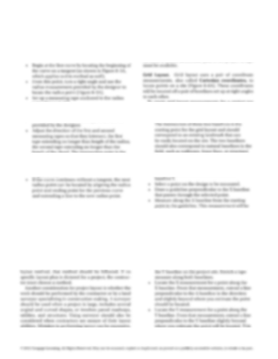
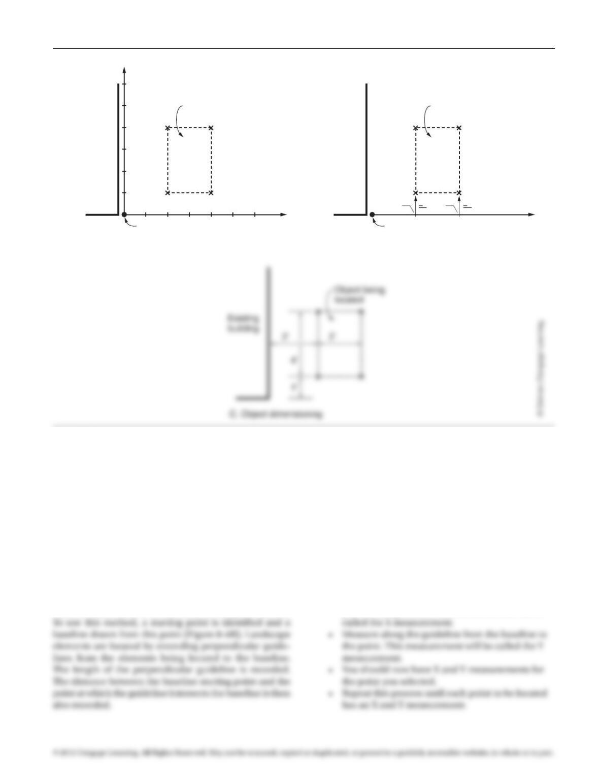
To create grid layout measurements for a project use
the following steps:
• On the plan draw two perpendicular baselines.
walls, or through an open area where a tape
measure can be placed to act as a temporary
baseline.
• Label one of the baselines X and the other
called the X measurement.
• Repeat this process for the Y guideline.
• You should now have X and Y measurements for
the point you selected.
• Repeat those steps until each point to be located
has an X and Y measurement.
To locate grid measurements on a project site use the
following steps:
• Identify the starting point, the X baseline, and
40 Exercise 8 Construction Staking
97171_08_ch08_p037-043.indd 40 14/06/10 8:44 PM
line should intersect with the line created in the
previous step.
• The intersection of the two lines is the location of
the point you are trying to locate.
• Repeat this process for all points that require
locating.
Baseline Layout. Baseline layout is similar to the grid
layout method but uses only one baseline for making
measurements and placing stakes rather than two. It is
useful for sites where only one clear baseline can be iden-
tified or established or for sites that are long and narrow.
To create baseline layout measurements for a project,
use the following steps:
• Draw one baseline on the plan. The baseline
should be in a location that can be easily laid out
on the site. Mark one end of the baseline as the
beginning point.
• Select a point on the design to be measured.
• Draw a guideline at a right angle to the baseline
that passes through the selected point.
• Measure along the baseline from the beginning
point to the guideline. This measurement will be
Exercise 8 Construction Staking 41
A. Grid layout
Beginning point
Baseline X
Baseline Y
Object being
located
Existing
building
4,12,1
4,42,4
B. Baseline layout
Beginning point
Baseline
Object being
located
Existing
building
2′ 4′
5′
5′
Figure 8–6 Construction staking methods.
97171_08_ch08_p037-043.indd 41 14/06/10 8:44 PM
To locate baseline measurements on a project site, use
the following steps:
• Identify the beginning point and the baseline on
the project site. Stretch a tape measure along the
baseline.
correct location of the point you are trying to locate.
• Repeat this process for all points that require locating.
Object Dimensioning. Object dimensioning is used
when the location of improvements can be measured off
existing landmarks such as structures (Figure 8–6C).
To create object dimensioning measurements for a
project use the following steps:
the measurement or align the measurement with a
second existing object.
• The existing object, or the measurement point of
the first object located, is then used to continue
measuring other points for the project.
To locate object dimensions on a project site, use the
following steps:
• Identify the existing object used to establish
other points.
Staking Offsets
Stakes and original markings are often disturbed during
the construction process. To avoid the process of restak–
ing a site, use offsets. To do so, use the following steps:
• Stake out the construction points of a project.
depending upon project conditions. So long as the
offset is consistent for every stake within a set of
points, it makes little difference what the distance
or direction is.
DISCUSSION
PREREQUISITE EXERCISES
Students should have successfully completed Exercise 1,
Construction Math, and Exercise 3, Measuring with Archi-
tects’ and Engineers’ Scales, before beginning this exercise.
MATERIALS REQUIRED
EXERCISE DESCRIPTION—PART A
To complete this exercise use the techniques described
previously to lay out each of the objects shown in
Figures 8–7 and 8–8. The drawings are to scale and must
be measured before staking.
42 Exercise 8 Construction Staking
B A
97171_08_ch08_p037-043.indd 42 14/06/10 8:44 PM
Exercise 8 Construction Staking 43
10′-0″
5′-0″
Radius
EXERCISE DESCRIPTION—PART B
To complete this exercise install construction staking for
the project identified in Figure 8–9 first using grid layout
and then with baseline layout.
97171_08_ch08_p037-043.indd 43 14/06/10 8:44 PM