141
Exercise 35
Constructing Wood
Railings and Stairs
OBJECTIVE
The objective of this exercise is to plan and construct
wood stairs and railings.
TEXTBOOK REFERENCE
Information related to this activity can be found in the
INTRODUCTION
After surfacing a deck, the finishing touches can be added
by building stairs and constructing railings. Stairs are
fairly uniform in style and construction, but proper instal-
lation is essential to ensure the safety of those who use the
Notched Stairs
Stairs consist of a collection of steps that allow for easy
travel up and down steep grades. Key components of a
on the riser. Stairs are supported by joist-like structural
members called carriages. Carriages are 2 × lumber that
are either notched and placed under the treads of a stair–
well, or uncut and placed along the sides of a stairwell
• Identify location for stair placement. Calculate
how many carriages are required to support the
than 4 feet.
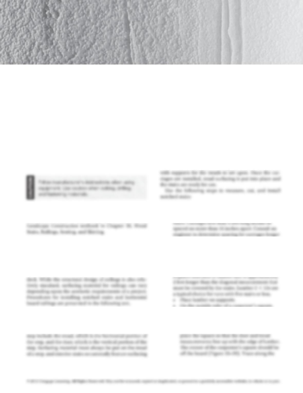
• Calculate the riser and tread dimensions using the
formulas presented in Figure 35–1 and Table 35–1.
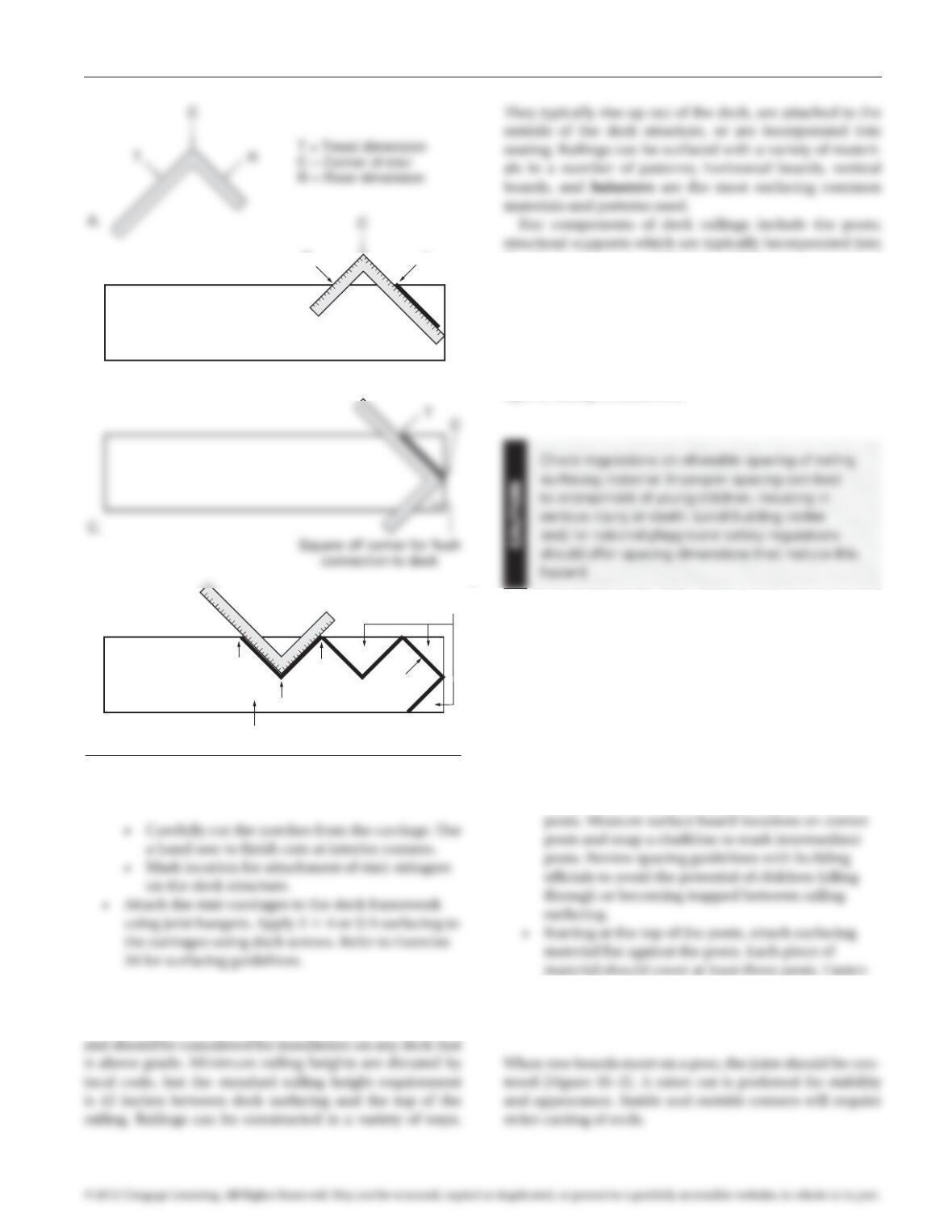
• Use the following process to mark and cut the
carriages using the calculated riser and tread
dimensions. Construction of notched carriages
• On the outside ruler of a carpenter’s square,
locate the riser dimension on the short side
and the tread dimension on the long side
(Figure 35–2A).
• Beginning near one end of the board,
97171_35_ch35_p141-144.indd 141 14/06/10 9:08 PM
142 Exercise 35 Constructing Wood Railings and Stairs
long side of the square to mark the location of
the top tread.
• Measure out the length of the tread along this
of the square to mark the location where the
carriage will connect flush with the deck.
• Position the square so that the riser and tread
measurements line up with the edge of the
lumber and the corner of the square is resting
on the board. The tread measurement should
be on the left, and the riser measurement
previous tread mark. Along both sides of the
square, trace the riser and tread locations
(Figure35–2D).
• Continue this process down the carriage
lumber until the required number of treads
and risers have been traced.
• At the bottom of the lowest riser, use the square
Table 35–1 Relationship Between Riser Height
and Tread Length in Stairs
2r + t = 26″ where: r = riser; t = trend
if r is . . . then t is . . .
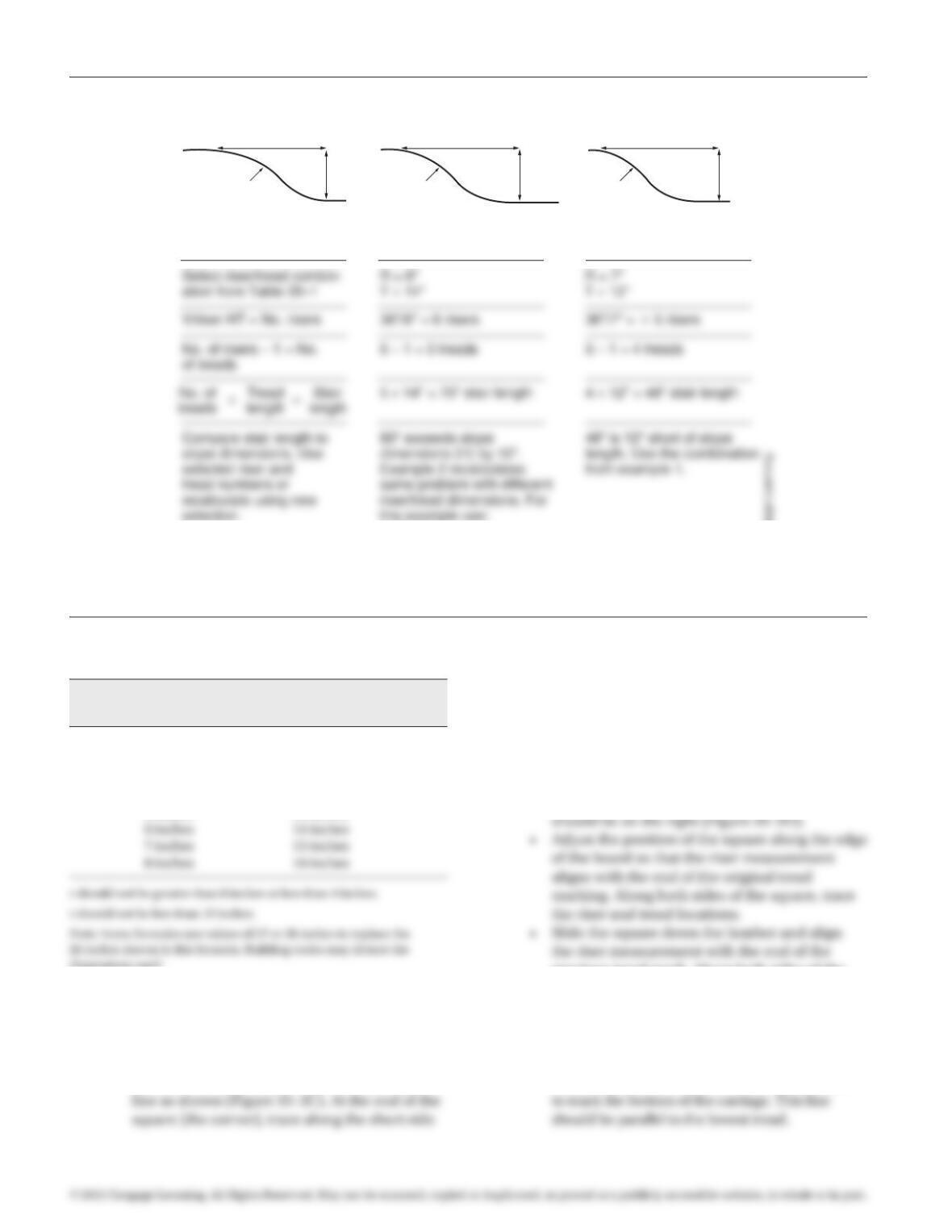
4 inches 18 inches
5 inches 16 inches
dimensions used.
Formula: Example 1: Example 2:
Convert H and V
to inches
5′ × 12 = 60″ = H
3′ × 12 = 36″ = V
5′ × 12 = 60″ = H
3′ × 12 = 36″ = V
*Stairs that do not match slope dimensions with riser/tread combinations in Table 35–1
will require special design considerations. Consult a design professional.
6–6″ risers
5–14″ treads, top one out
into hill.
H
Slope Slope Slope
V
5′
3′
5′
3′
Figure 35–1 Stair calculations.
© Delmar/Cengage Learning.
97171_35_ch35_p141-144.indd 142 14/06/10 9:08 PM
Exercise 35 Constructing Wood Railings and Stairs 143
the deck structure; stringers, which support vertical
surface covering; and the surfacing. Railings can also be
designed to include trim and caps.
Use the following steps for installing a typical hori-
zontal board surface railing. (Note: Construct railings
according to the construction documents provided for a
design. This installation procedure is typical of only one
type of railing installation.)
• Verify location of railing posts. Maximum spacing
should be 4 feet, with a post at every corner and
at locations where railing changes direction. If it
is not installed with the deck structure, notch the
deck surfacing and bolt additional 4 × 4 posts to
deck framework where necessary.
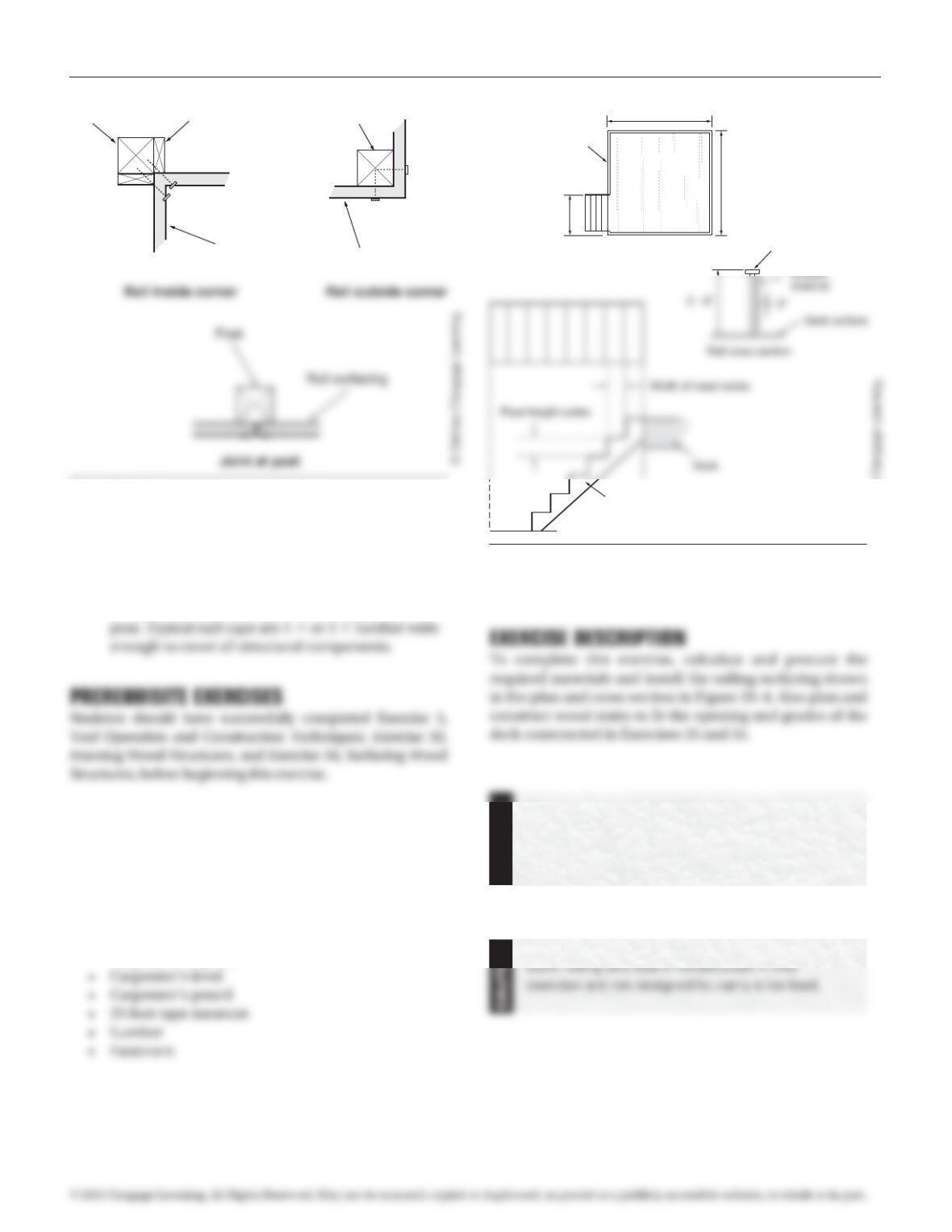
• Railings at inside corners will need 2 × 4 cleats
attached to the surface of the 4 × 4, to which fence
surfacing can be attached (Figure 35–3).
• Carefully mark out surfacing locations on the
securely to posts using deck screws. Common
surfacing materials include 2 × 6s, 2 × 8s,
and a combination of 1 × and 2 × lumber.
T
T
B.
D.
Continue
for all
stairs Cut line
C
R
R
Scrap
Stair carriage
Figure 35–2 Marking and cutting notched stair carriages.
Railings
Railings enhance both the safety and appearance of a deck
© Delmar/Cengage Learning.
97171_35_ch35_p141-144.indd 143 14/06/10 9:08 PM
144 Exercise 35 Constructing Wood Railings and Stairs
• Continue adding surfacing until the bottoms of the
posts are reached.
• Attach a 2 × 8 rail cap running flat over the top
of the posts. Fasten using two deck screws per
MATERIALS REQUIRED
• Cordless drill and bits
• Circular saw
• 50 foot extension cord and access to 120V GFCI
circuit
• Hand saw
• Claw hammer
• Carpenter’s square
Operate power equipment under supervision.
Serious injury or death could result
from improper use of equipment. Follow
manufacturer’s instructions.
Rail surfacingRail surfacing
2 x 4 Cleats Post
Post
Figure 35–3 Railing corner installation details.
Deck surface
Rail
8′-0″
8′-0″
3′-0″
Cap
2 x 6
Stair
carriage
Figure 35–4 Plan of deck showing railing and stair location, and
railing and stair cross section.
© Delmar/Cengage Learning.
97171_35_ch35_p141-144.indd 144 14/06/10 9:08 PM