
77
Exercise 20
Irrigation System
Installation
OBJECTIVE
TEXTBOOK REFERENCE
Information related to this activity can be found in the
INTRODUCTION—PART A: SPRAY
IRRIGATION SYSTEMS
Irrigation systems provide water for plant growth in all
types of landscape settings. Effective irrigation systems
begin with the careful design and planning of the entire
installation. Considerations that must be incorporated
into the design of an irrigation system include:
must provide adequate pressure and volume
to deliver the required amount of water to all
zones in the system. Large sites often require the
creation of zones simply to provide for ample
water pressure and volume throughout the site.
• Installation of a backflow prevention device.
to prevent contamination of the water source
to which the system is connected. All backflow
devices require that the mounting height of the
valve be above the highest irrigation head, with
switch that turns irrigation zones on and off.
This controller must be located with access
to power through a dedicated GFCI circuit,
easy connection to the irrigation system, and
a location where the system operator can gain
access for maintenance. Any sensors that monitor
or control the system must also be accessible to
the controller.
Connection to a water supply and electricity
source requires the assistance of a licensed
97171_20_ch20_p077-087.indd 77 14/06/10 8:56 PM

78 Exercise 20 Irrigation System Installation
CAUTION
Trenching
Trenching for irrigation projects can be completed by
hand or with rented trenching machines. Excavate only
the amount of trench that will be worked on in any
given session. Excavation depths vary depending on the
Installing Wiring
After trenching is complete, install the control wiring from
the controller to the manifold or to each valve. Wiring
connections should be made using waterproof wire nuts
to reduce the chance of system failure due to corrosion.
Most wiring installations for irrigation are 18 gauge, but
14or 12gauge will carry more voltage.
Main Line Installation
Connecting pipes outside the trench makes for easier
work and reduces the possibility that foreign materials
will enter piping.
open flames, and work in a well-ventilated
location.
Manifold and Valve Installation
Systems may be designed to use a valve manifold situ-
ated in one location or valves that are positioned near
Valves that are distributed throughout the site are set
below grade and placed in valve boxes. To position and
assemble this type of valve, follow these steps:
• At each location where a valve is to be located,
excavate an opening the size of the valve box, plus
6 inches on each side and 4 inches below. The
location for the excavation should be centered
• Hold the valve in the desired location and mark
the main for trimming.
• Trim the main.
• If a sump has been installed, place a tee connected
to a ball valve drain directly over the sump. Add
6 inches of piping to the valve side of the tee. Glue
all fittings together.
97171_20_ch20_p077-087.indd 78 14/06/10 8:56 PM
Exercise 20 Irrigation System Installation 79
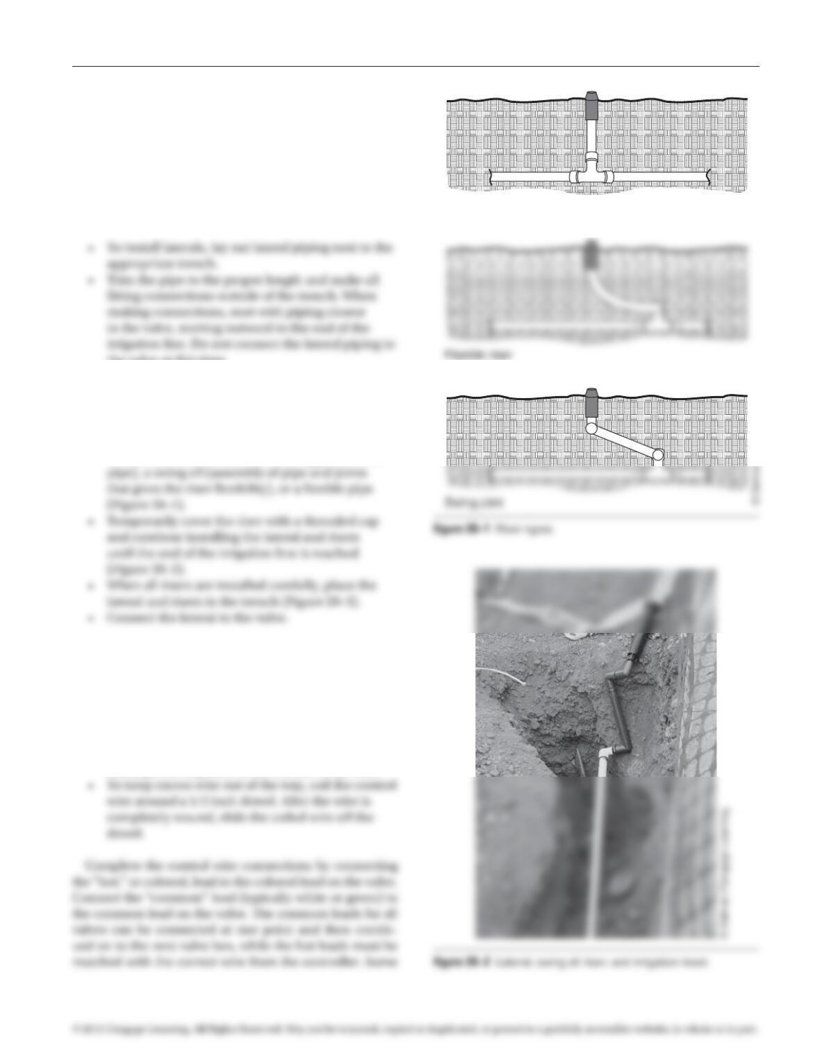
Lateral and Riser Installation
From each valve location extends a network of pipes that
thread through the site or zone, connecting the valves
to each irrigation head location. These pipes are called
laterals. At each irrigation head location, a connecting
pipe called a riser runs from the lateral to the irrigation
head. Each lateral in an irrigation system typically has
several riser locations.
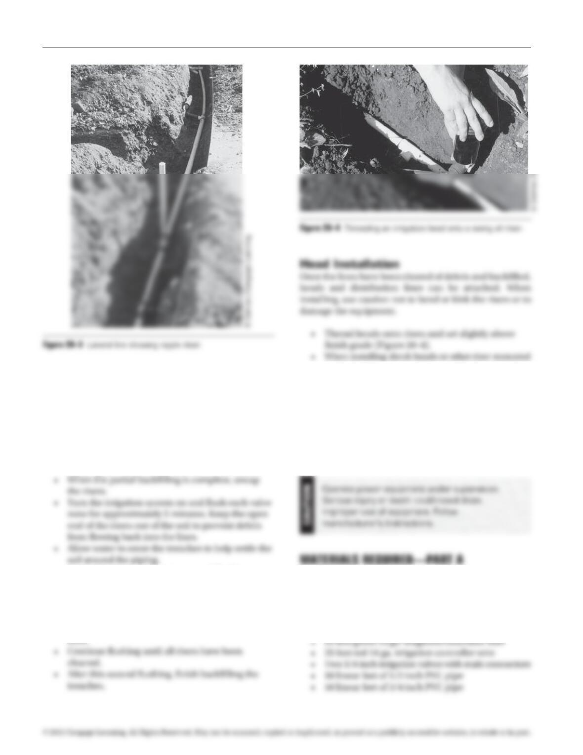
the valve at this time.
• When a riser location is encountered, cut the
lateral and glue a tee at the cut end. Verify that
the placement of the tee and riser will position
the irrigation head in the correct location without
twisting or bending the riser. Do not install the
head at this time. Risers can be a nipple (vertical
Valve Box Installation and Valve Wiring
• Place a valve box over the valve and seat the box
securely on the granular base.
• Verify that the controller wires are inside the valve
box.
• Cover any openings in the box by duct taping
heavy pieces of plastic to the outside of the box.
Standard riser
97171_20_ch20_p077-087.indd 79 14/06/10 8:57 PM
80 Exercise 20 Irrigation System Installation
wiring schemes may be different, so verify the correct con-
nections on the wiring diagram.
Backfilling and Flushing
• Carefully backfill the irrigation lines to half to two
thirds full. Do not backfill around riser locations.
Do not compact the backfill at this time and avoid
stepping on the lines.
• Recap the risers and begin a second flushing,
this time going riser to riser and removing one
riser cap at a time. In each zone, first remove the
cap on the riser closest to the valve and flush for
2minutes, then recap the riser and repeat for the
next riser in line. Repeat for each riser in each
zone.
heads that project out of the ground, place a post or
#4 rerod next to the riser for stability. Bury the post
or rerod at least 2 feet into the ground.
PREREQUISITE EXERCISES
Students should have successfully completed Exercise
5, Tool Operation and Construction Techniques, before
completing this exercise.
• Access to water source using a 1/2 inch garden
hose and a GFCI duplex outlet
• One irrigation controller with a minimum of two
zones. Controller should be wired with a grounded
plug.
• 50 feet white 14 ga. irrigation controller wire
97171_20_ch20_p077-087.indd 80 14/06/10 8:57 PM
Exercise 20 Irrigation System Installation 81
• Two valve boxes
• Three assembled swing ells with 1/2 inch Mips
• Two flexible risers with 1/2 inch Mips
• One fitting 3/4 inch S×S×S tee
• One reducing adapter 3/4 inch (slip end) to 1/2inch
(threaded end) SxFips (for hose connection)
• Assorted 1/2 and 3/4 inch threaded and slip
90 degree elbows, couplings, and caps
• Assorted waterproof wire nuts
• Joint tape
• 3 foot section of #4 rebar
• 5 pound sledgehammer
• Adjustable crescent wrenches
• Small table on which to set controller
EXERCISE DESCRIPTION—PART A
To complete this exercise, install the basic spray irriga-
Alternative Exercise
This alternative exercise provides practice in pipe cutting,
INTRODUCTION—PART B: DRIP IRRIGATION
SYSTEMS
Drip irrigation is an alternative to spray system irrigation
and uses water more efficiently. Drip systems are low-
pressure systems that precisely distribute water directly to
the root zone of plants rather than distributing water over
an entire planting area. Drip irrigation uses a variety of
water distribution techniques ranging from emitters that
slowly drip small amounts of water to micro-sprays and
ability to protect the system components from freeze is
difficult, and drip systems are more prone to plugging
and failure than sturdier spray systems. Unless placed
below soil surface, drip systems are not effective at water-
ing turf areas. Despite these limitations, the drive for
sustainability has increased the use of drip irrigation as a
method to reduce water consumption.
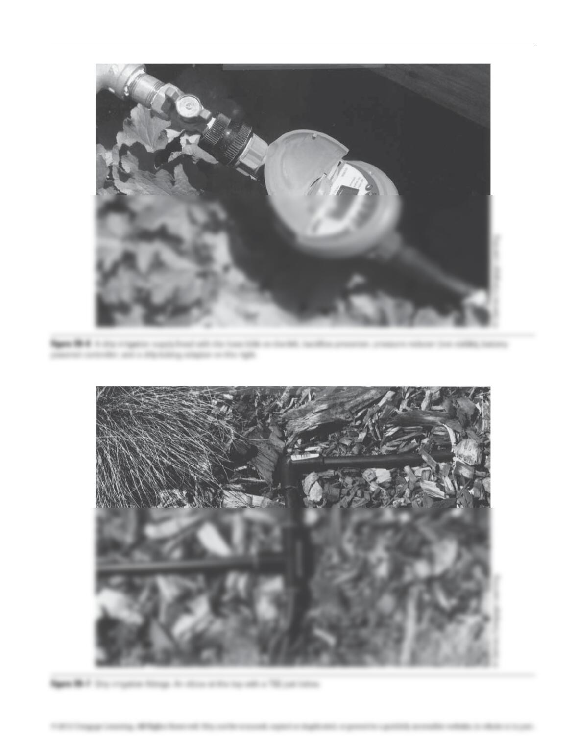
require a backflow preventer and pressure regulator. A
timer (usually battery operated) will be necessary if the
drip system is not on a spray system valve or the owner
does not want to manually operate the system. Each of
these fixtures is typically supplied with threaded fittings
that connect to the hose bibb/water line and each other
using typical plumbing connections (Figure 20–6). Also
each of the desired fixtures in line, and at the end
of this supply head, install a tubing adapter.
• The distribution line will slip into the compression
line is laid out along the paths that will best serve the
plant material being irrigated. For areas where the
distribution line does not come in contact with every
plant, branch lines of ¼“ connector tubing can sup-
ply water to additional plants. For smaller sites (50–75
emitters), a single distribution line can be split into
branch lines to better access the plant material. Large
97171_20_ch20_p077-087.indd 81 14/06/10 8:57 PM
82 Exercise 20 Irrigation System Installation
5 Fipt
reducing
adaptor 5 MIPS
reducing
adaptor
5 5 90°
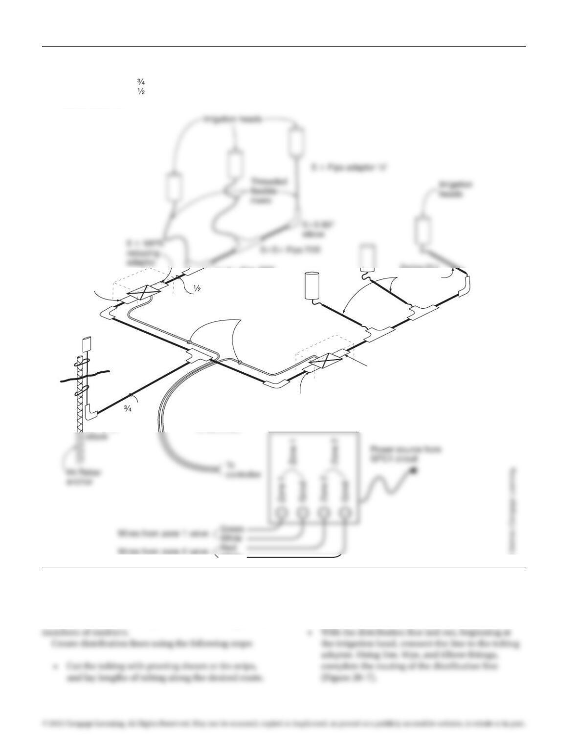
Valve Zone 2
Valve Zone 1
White and green
controller wires
Valve box
55 90°
elbow
Swing ELL
risers with
MIPS
55 Fips TEE
55 Fips TEE
55 Fips TEE
” PVC to
end of lateral
” PVC
to valve
555
TEE
Max. 20′
from valves
to controller
White
5 MIPS
adaptor
5 MIPS
adaptor
Water
source
hose
connection
Valve box
Notes:
-All pipe and fittings ” PVC from supply to valves
-All pipe and fittings ” PVC beyond valves
-Burial Depth 12″
Figure 20–5 Irrigation system exercise.
sites may require the creation of additional irrigation
heads and distribution systems to serve significant
Leave extra tubing to allow for adjustments in
alignment.
© Delmar/Cengage Learning.
97171_20_ch20_p077-087.indd 82 14/06/10 8:57 PM
Exercise 20 Irrigation System Installation 83
97171_20_ch20_p077-087.indd 83 14/06/10 8:57 PM
84 Exercise 20 Irrigation System Installation
• If a system is installed on a sloping site, additional
pressure regulators may need to be installed in the
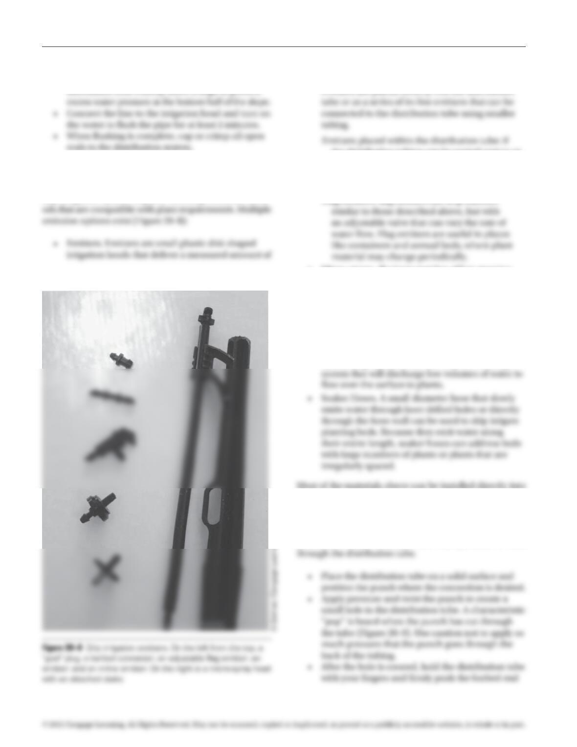
Emitters
Getting appropriate amounts of water to the plants in a
drip irrigation system requires choosing emission meth-
water over a given period of time. Typical emitters
provide ½ , 1, or 2 gallons of water per hour.
the distribution tubing can be routed next to or
through the plants being irrigated, distribution
tubing that has low-volume emitters placed
directly into the tube is available.
Flag emitters: flag emitters are drip emitters
• Micro-sprays. If a large number of low-growing
plants require irrigation and it is impractical to
route an emitter to each plant, micro-sprays can
distribute a low-volume spray similar to the heads
used in spray systems. Micro-sprays have a limited
volume and radius of spray, but can be useful in
small areas of ground covers and planting beds.
• Bubblers. For planting areas that are best irrigated
by flooding, bubblers can be installed on a drip
the distribution line or separated from the distribution
line through the use of ¼“ tubing.
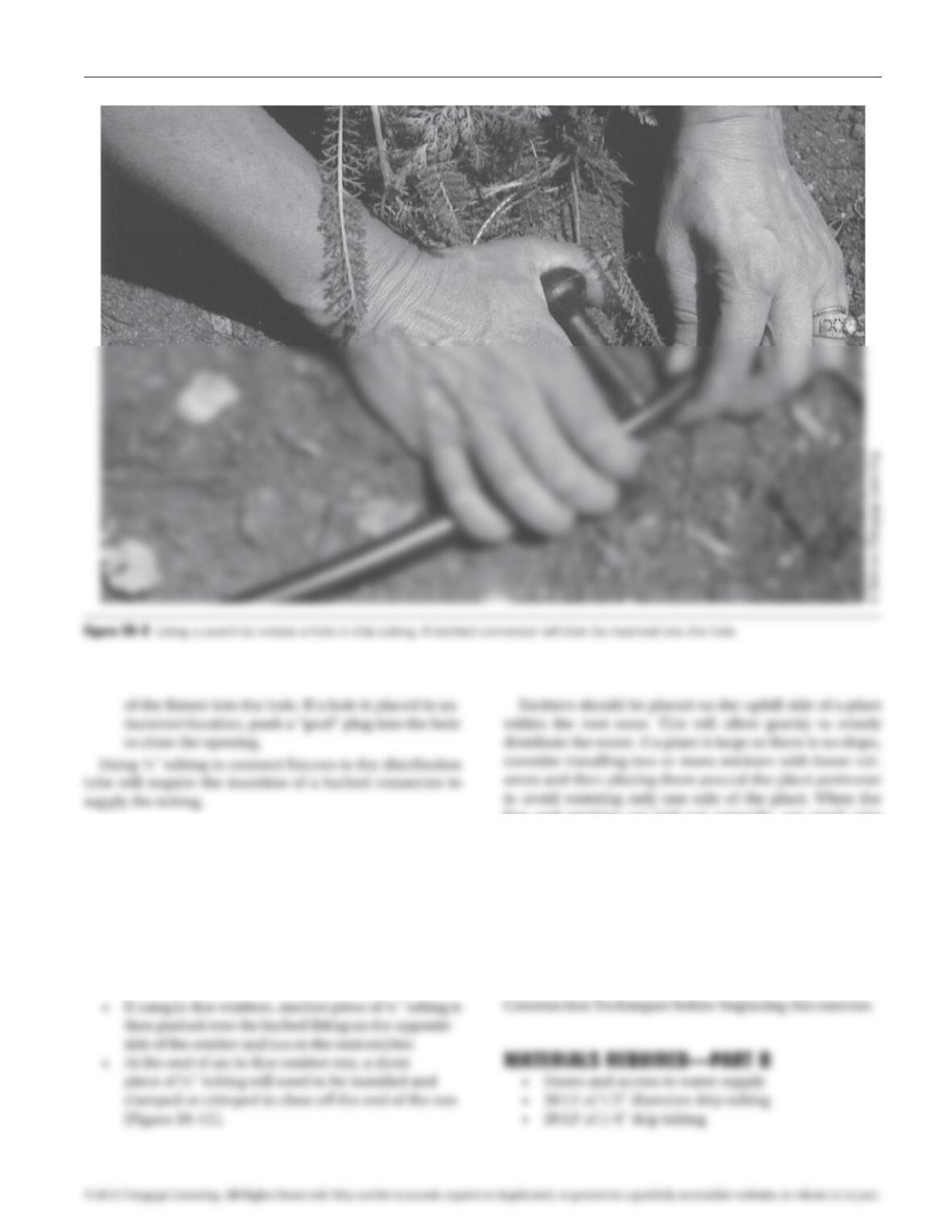
Installation of emitters and/or ¼“ connection tubes
requires the use of a special tool termed a punch. The
punch is a small diameter awl that punches a hole
97171_20_ch20_p077-087.indd 84 14/06/10 8:57 PM
Exercise 20 Irrigation System Installation 85
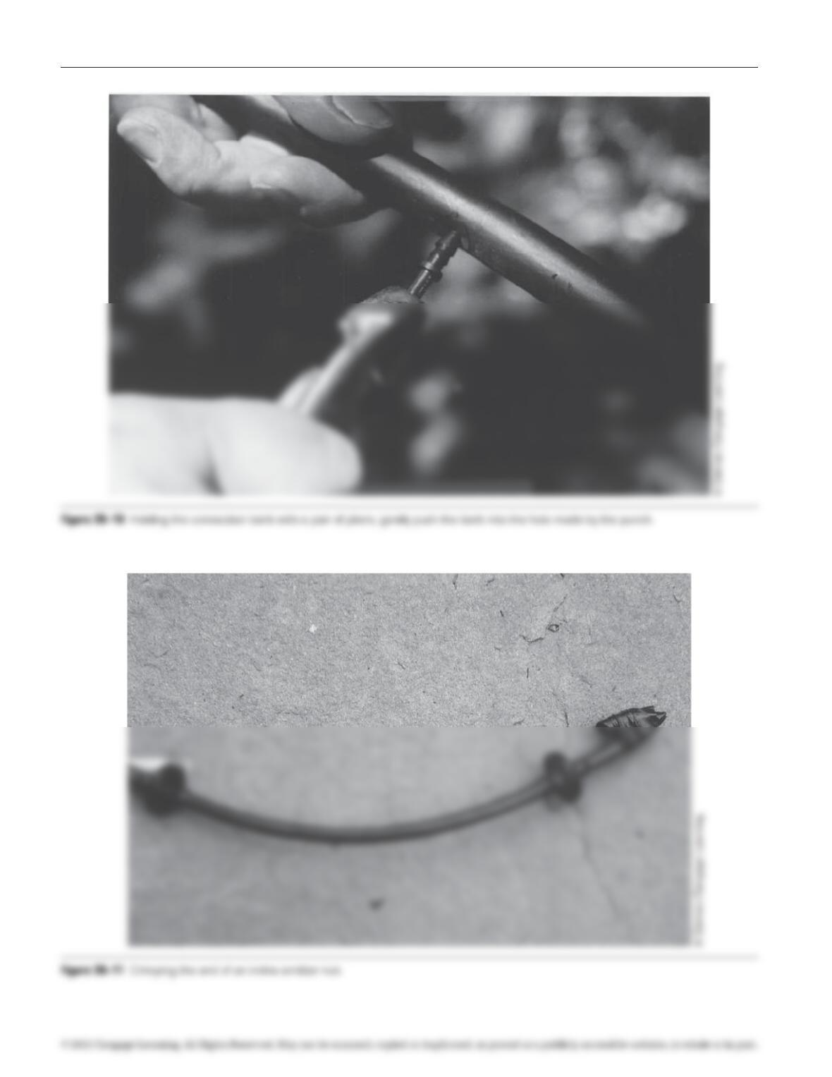
• Place the distribution tube on a solid surface and
hold a barbed connector with a pair of pliers.
• Use a twisting motion to push the connector
through the hole made by the punch
(Figure 20–10).
• Once firmly inserted, ¼“ tubing can be pushed
over the open end of the connector and run to
the fixtures on that line. Pushing tubing over the
barbed end connects emitters.
line and emitters are laid out correctly, use small wire
stakes to hold the line in place and cover the tubing with
mulch. Flag emitters will need to be adjusted to achieve
the desired flow rate, and micro-sprays will need to be
adjusted to aim the spray in the proper direction.
PREREQUISITE EXERCISES
Students should have successfully completed Exercise 1,
Construction Math, and Exercise 5, Tool Operation and
97171_20_ch20_p077-087.indd 85 14/06/10 8:57 PM
86 Exercise 20 Irrigation System Installation
97171_20_ch20_p077-087.indd 86 14/06/10 8:57 PM

Exercise 20 Irrigation System Installation 87
• Plumbing thread tape
• Drip irrigation system hose bibb connector
• Drip system pressure regulator
• Two spray emitters
• 20 wire anchors
• Tubing cutters
Cap
Barbed
connectors typ.
Compression
tubing
adaptor
Timer
Pressure
regulator
preventer
Hose bibb
/2“
1
/2“
1
/2“
1
/2“
1
/2“
90° Elbow
1
/4“1
/4“
6-16 Gal/Hr Inline emitters
Crimp ends
97171_20_ch20_p077-087.indd 87 14/06/10 8:57 PM