
70
Exercise 19
DC Lighting Installation
OBJECTIVE
The objective of this exercise is to properly install direct
current low-voltage landscape lighting.
Locate all utilities before beginning construction.
TEXTBOOK REFERENCE
Information related to this activity can be found in the
INTRODUCTION
Custom DC lighting systems can add life to the eve-
ning hours of a landscape. While kits are available to
install home lighting, more reliability and durability are
Guidelines for Planning a Lighting System
When planning a lighting system, the designer uses
some standard guidelines and mathematical formulas
to determine the parameters of a lighting circuit. These
guidelines will help the designer determine how long the
lighting run can be, how many lights can be placed on a
circuit, and whether the lights will function properly.
Add these factors to the decisions that are required
about the style of fixture and aesthetic function of the
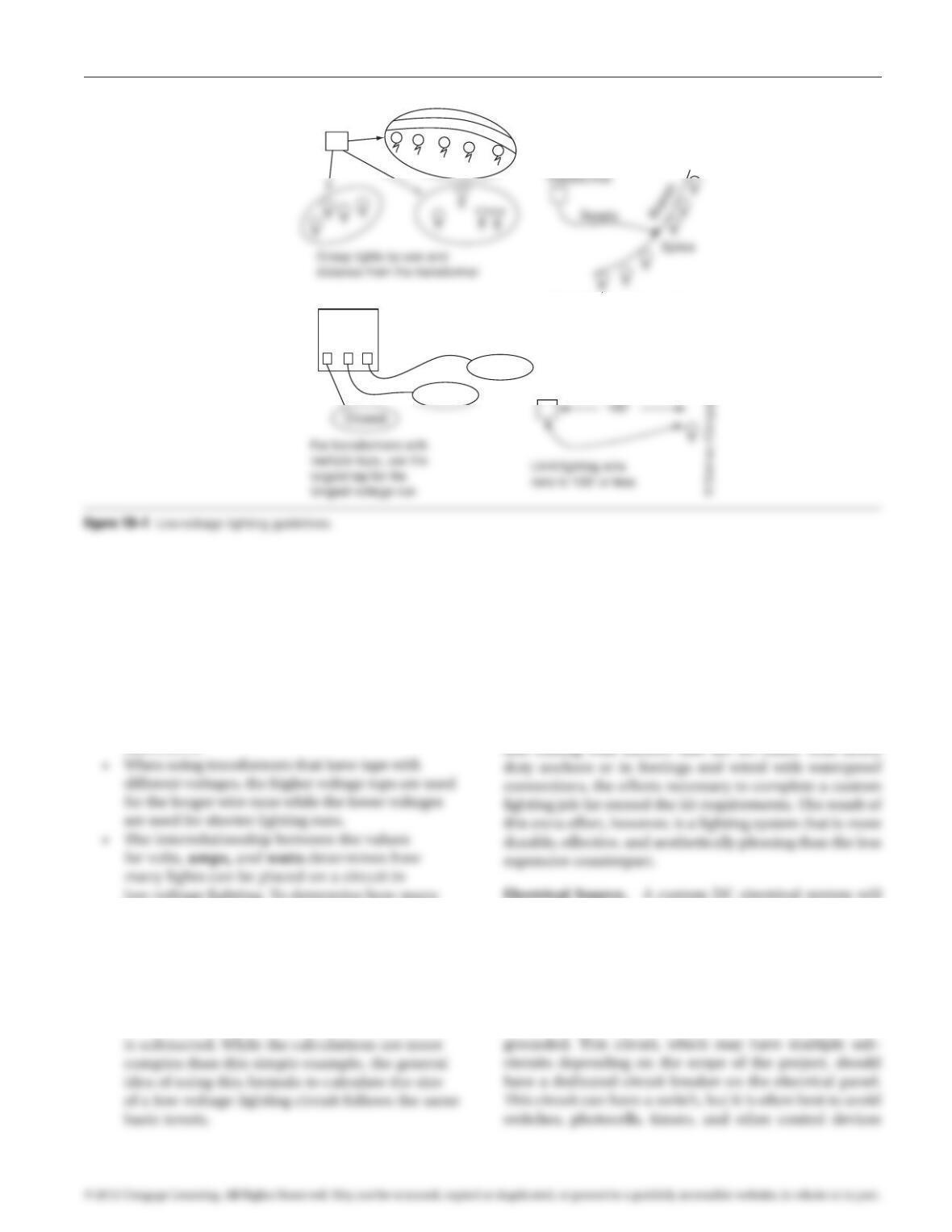
functions work best on individual circuits. For
example, path lights are best grouped on the same
circuit rather than grouped with several different
of placing lights directly on the wire supplying the
circuit, lights should be placed on a branch line
that is then connected in the center of that branch
line to the wire supplying power to the circuit.
This evens out the voltage drop among all of the
a much wider range, often between 14 and 6 volts
per circuit without losing lighting quality or lamp
life. LED’s also allow many more fixtures to be
placed on a circuit than traditional lamps.
97171_19_ch19_p070-076.indd 70 14/06/10 8:55 PM
Exercise 19 DC Lighting Installation 71
• Because of voltage drop on long circuits, wire
run lengths are typically limited in length to
100 feet. This keeps the lights on the circuit
from dimming due to the lack of voltage. Unlike
other lamp types, large numbers of LED lights
can be placed on a longer circuit because of the
LED’s low wattage and compensation for voltage
differences.
low-voltage lighting. To determine how many
watts of lighting can be placed on a circuit, the
formula Watts = Volts × Amps can be used.
An example is that a 10-volt circuit at 15 amps
would be able to support 150 watts of lighting,
or fifteen10-watt bulbs. The actual number of
lamps on a circuit would be even fewer when
the loss of voltage for every foot of the wire run
Installation
One primary difference between the packaged kit lighting
systems and custom low-voltage DC electrical systems is
the increased quality of the products for a custom instal-
lation. Another difference is the piece-by-piece instal-
lation required for a custom system. Beginning with a
dedicated power supply rather than an electrical outlet,
Electrical Source. A custom DC electrical system will
require that a licensed electrician provide a 115–120 volt
circuit to the location where the transformer(s) will be
located. This supply line should be on a separate GFCI
circuit and should supply only the lighting system. When
routing the electrical supply to an exterior location, all
components should be placed in conduit a minimum
of 18 inches deep and should be waterproofed and
Transformer
Transformer
Transformer
Put lights in a zone on a
branch wire run, then
connect the branch run to
the supply at the center
Path
Farthest
Voltage
Ta p
12 13 14
97171_19_ch19_p070-076.indd 71 14/06/10 8:55 PM

72 Exercise 19 DC Lighting Installation
as spot lights or flood lights. Spot fixtures focus a narrow
beam of concentrated light at an object, whereas flood
fixtures cast a wide beam of diffused light. The intensity
and spread of the light beam for each of these fixtures
on this circuit and place such controls on the individual
circuits coming out of the transformer.
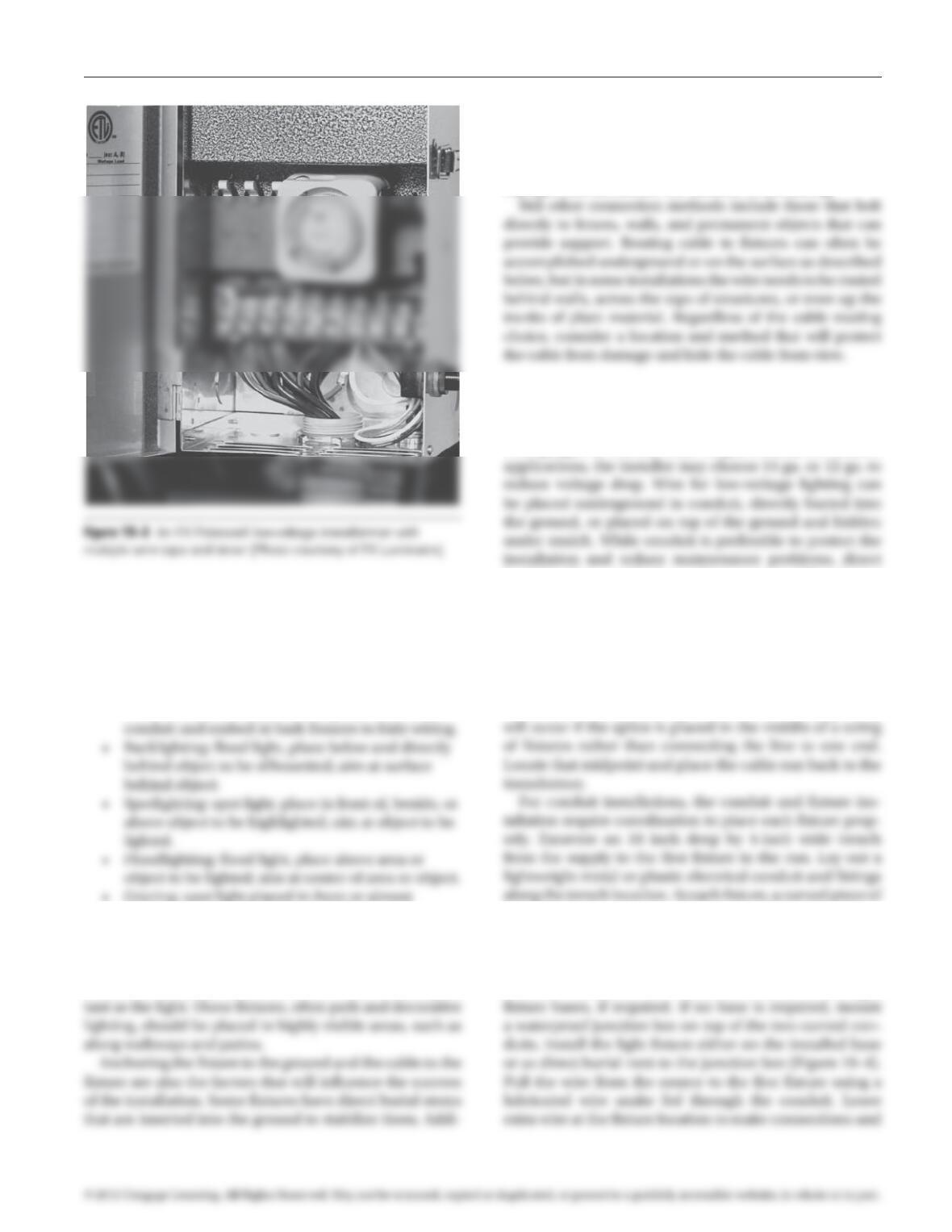
Transformers and Hubs. Electrical sources for custom
low-voltage systems typically follow one of the follow-
ing three distribution methods. The first is mounting
a single transformer and wiring each circuit from that
transformer. This method requires the positioning of
the voltage drop due to the shorter cable runs. Hubs
can also equalize voltage among lighting runs or feed to
other hubs. The third method is to run separate electri-
cal circuits to multiple low-voltage transformers located
close to the lighting fixtures the transformer will serve.
Each method will require a transformer that is sized to
handle the electrical demands of the system. Transform-
ers are typically available in a range of wattages and with
varying numbers of circuits that can be installed. Due to
the variability of lighting fixtures, number of fixtures, and
length of lighting runs, installation of a transformer that
has multiple circuits (or voltage taps) will aid in provid-
ing adequate power to multiple wire runs (Figure 19–3).
Figure 19–2 Transformer and wiring options for DC lighting.
Transformer
Power
source
Transformer
Light
fixtures
Light
Power
source
© Delmar/Cengage Learning.
97171_19_ch19_p070-076.indd 72 14/06/10 8:55 PM
Exercise 19 DC Lighting Installation 73
tional fixtures may require the pouring of a small concrete
base, or even a concrete footing to properly anchor them.
Installing fixtures so that frost, erosion, soil settling, and
other disturbances do not shift the fixture (and the result–
ing light) should dictate the method of anchoring.
Wiring and Connections. For most custom low-voltage
electrical installations, the wiring and connection com-
ponents are significantly upgraded from kit installations.
Wire gauges for kits are often 18 ga., whereas for custom
burial is often used for low-voltage systems. When laying
out wire runs, leave slack line along each run to allow for
adjustment of fixture and cable locations. Unless you are
using conduit, do not bury the wire until the system has
been completely laid out and tested. Place the cable runs
from fixture to fixture. Determine where the cable from
the transformer should be spliced into the fixture run.
When positioning splicing locations, less voltage drop
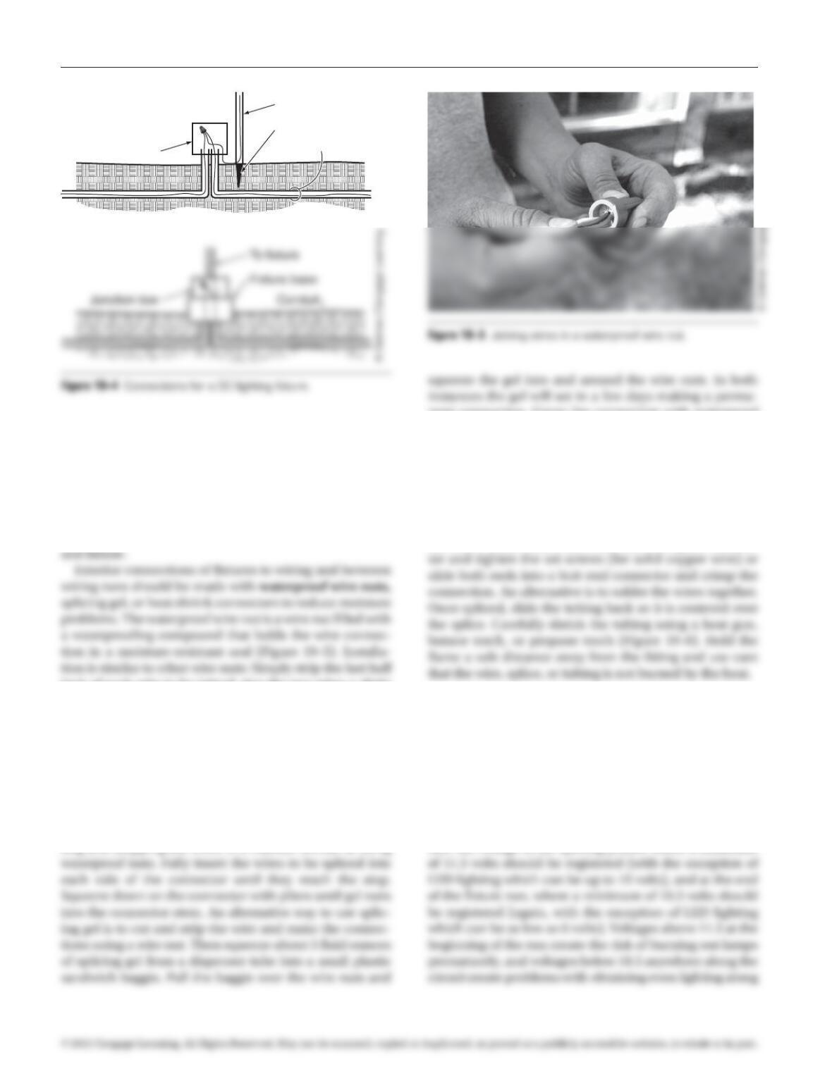
conduit should turn toward the surface at the fixture loca-
tion. A separate curved piece of conduit should lead back
down into the trench to start the conduit run to the next
fixture. Cut the conduit to fit between fixtures and join.
Place the conduit in the trench and backfill. Install light
• Uplighting: spot or flood fixtures, place fixture
on ground and aim up into plant or object to be
featured.
• Downlighting: spot light, place fixture above head
height in plant and aim toward ground; hide
fixture in branches, if possible; place wire in dark
adjacent to object being lit. Aim directly upward.
In addition to installations where the light source is to
be hidden, a wide array of fixture choices is available for
situations where the character of the fixture is as impor–
97171_19_ch19_p070-076.indd 73 14/06/10 8:55 PM
74 Exercise 19 DC Lighting Installation
nent connection. Cover the connection with waterproof
tape for even more protection from the elements.
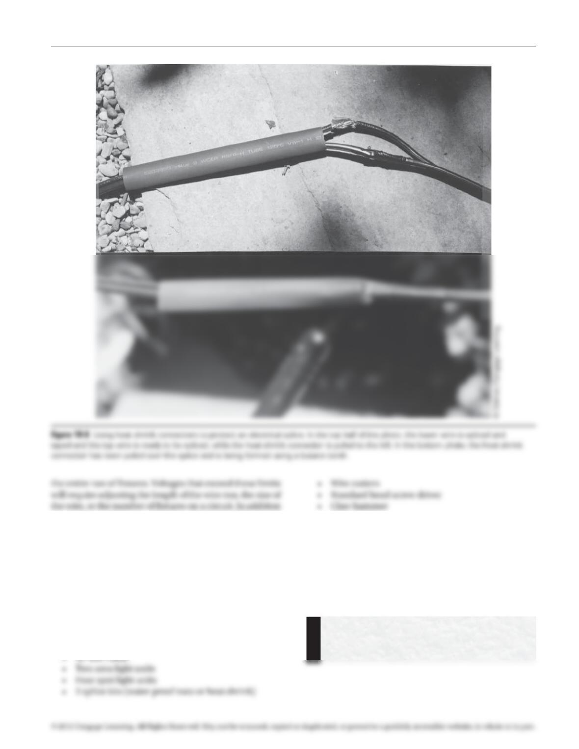
Heat shrink connectors are another way to provide a
weatherproof connection. Select a connector that is large
enough to fit over the cables and the splice, typically
½ inch flat or diameter. Begin by cutting and stripping
the cables in a manner similar to using waterproof nuts.
Slide the piece of tubing lined with adhesive over one of
the wires. Either insert the wires into the splice connec-
Testing and Adjusting the Custom
Installation
Testing and adjusting the custom installation will require
multiple steps. Initial tests should come when the wir–
ing runs are established in the form of voltage checks at
the splicing points and ends of runs. After the wires have
been connected to the transformer and the fixtures, use a
digital voltmeter touching each of the two leads to mea-
sure the voltage at the splicing points, where a minimum
slight adjustments. Continue to pull cable for all fixtures
in the run. Make connections at the fixtures, and then
make connections at the power source. Connections for
DC fixtures are often accomplished within the fixture,
either in the bulb housing, a built-in junction box, or a
base. When making connections, even inside a junction
box, follow guidelines to reduce connection problems
inch of each wire to be joined, give the two wires a slight
twist together, then slip the nut on and turn in a clock–
wise direction until snug. Making connections within a
waterproof junction box is also an aid to reducing future
maintenance problems. When installing bulbs or making
other friction type connections, coat the tabs or threads of
the bulb with a light coat of Vaseline to reduce corrosion
problems with connections.
To make a more permanent waterproof connection
using a splice gel connector, begin the process by cut–
ting and stripping the wires in a manner similar to using
Fixture anchor
To fixture
Junction box Conduit
97171_19_ch19_p070-076.indd 74 14/06/10 8:55 PM
Exercise 19 DC Lighting Installation 75
to checking voltages, a nighttime check should be made
of fixture placement to assure that the desired effect is
being obtained. Fixtures that are not creating the lighting
patterns desired should be adjusted.
PREREQUISITE EXERCISES
None.
MATERIALS REQUIRED
• Controller
• Utility knife
EXERCISE DESCRIPTION
To complete this exercise install and test a DC exterior
lighting system (Figure 19–7). The system should include
a controller with two taps, timer, and photocell, spotlight-
ing, and area lighting.
Follow manufacturer’s instructions. Verify that
power has been turned off before working with
electrical systems.
97171_19_ch19_p070-076.indd 75 14/06/10 8:56 PM
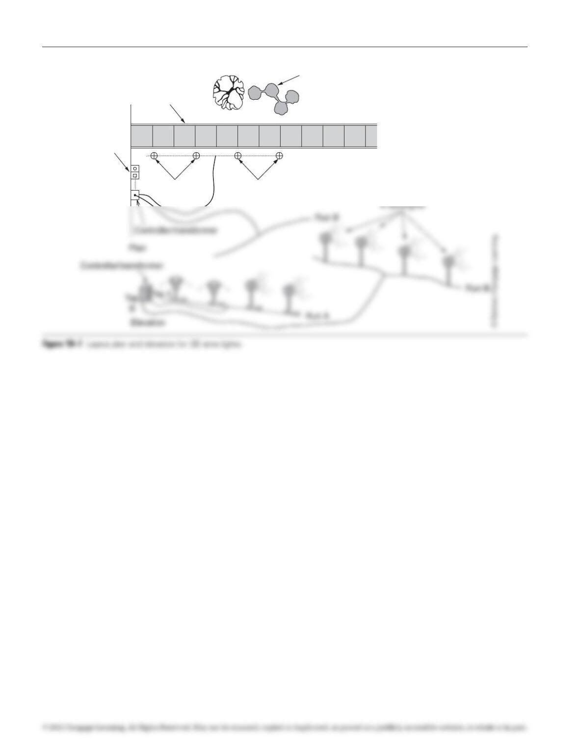
76 Exercise 19 DC Lighting Installation
Featured
plant material
2 Spotlights. Aim at
featured plant material
2 Area
fixtures
GFCI
outlet
Run A
Sidewalk
97171_19_ch19_p070-076.indd 76 14/06/10 8:56 PM