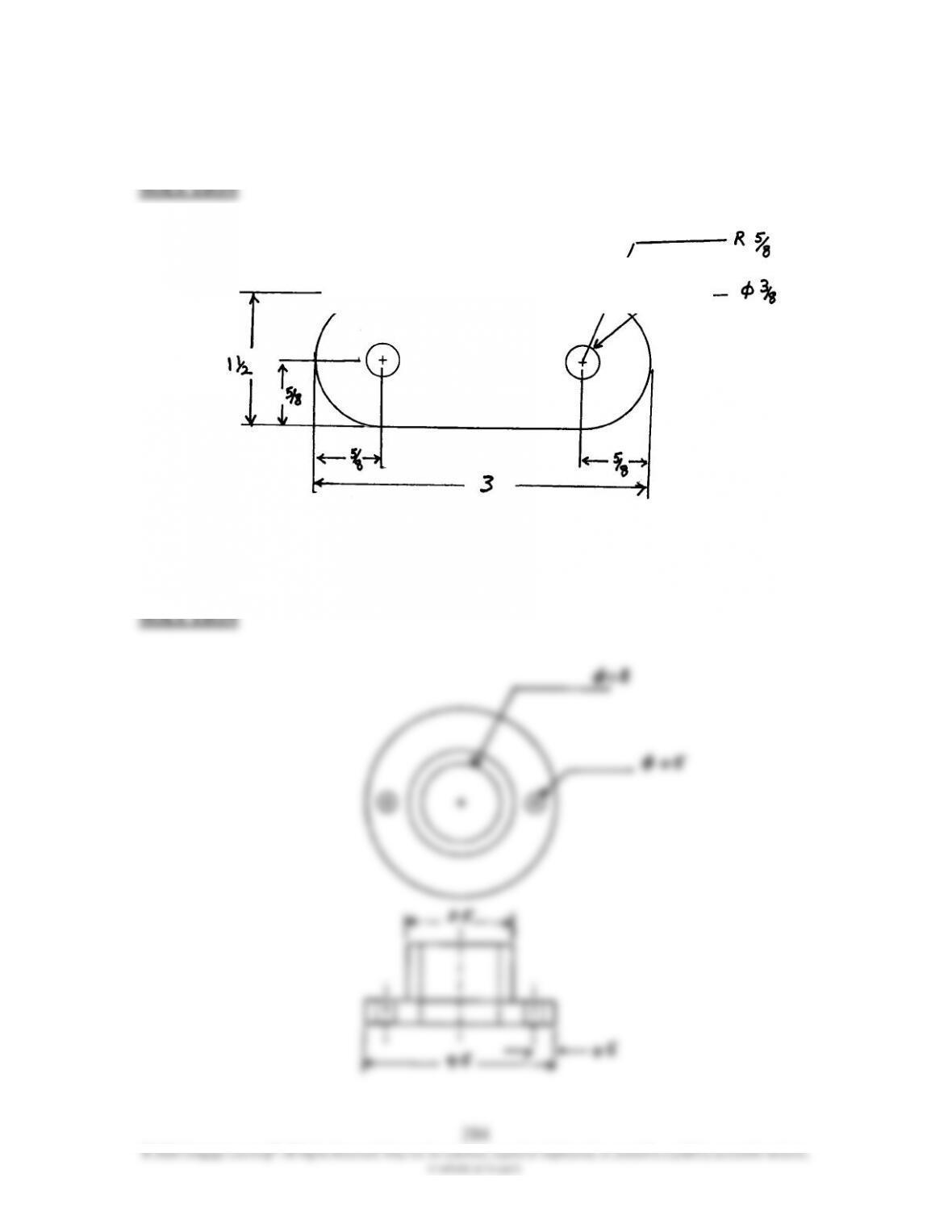
16.26 For Problems 16.24 through 16.28, using the rules discussed in this chapter, show
the dimensions of the views shown.
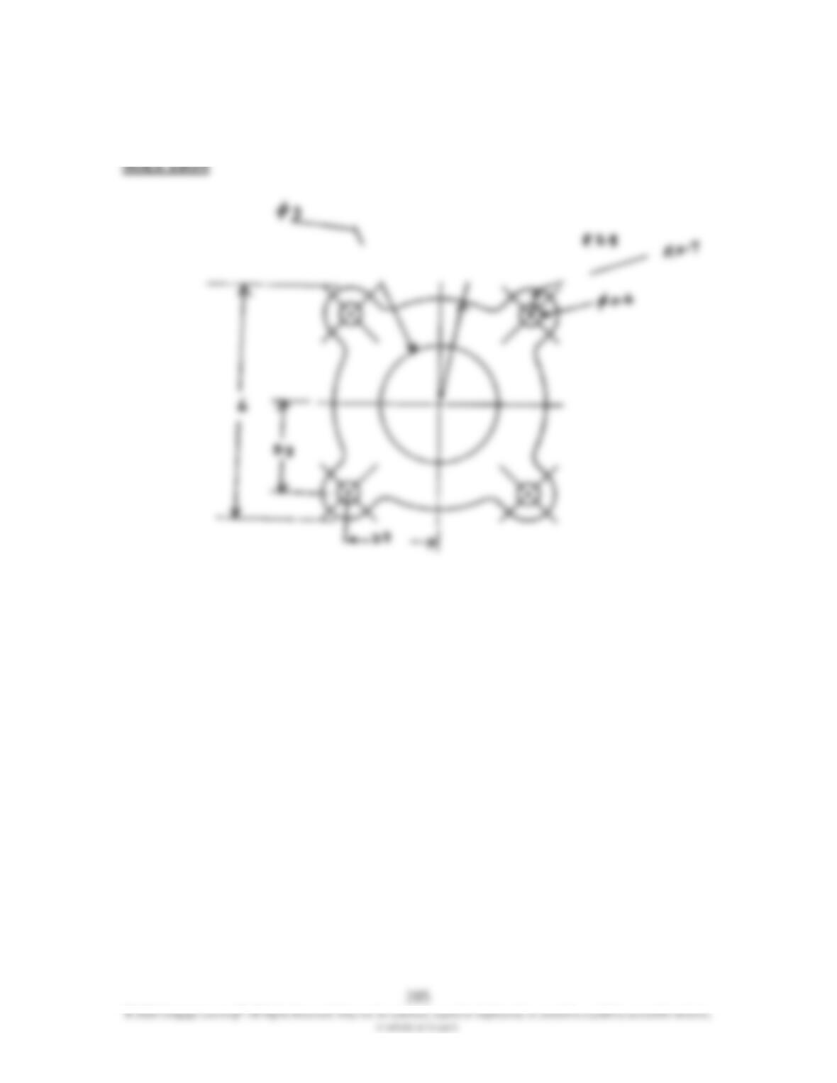
16.27 For Problems 16.24 through 16.28, using the rules discussed in this chapter, show
the dimensions of the views shown.
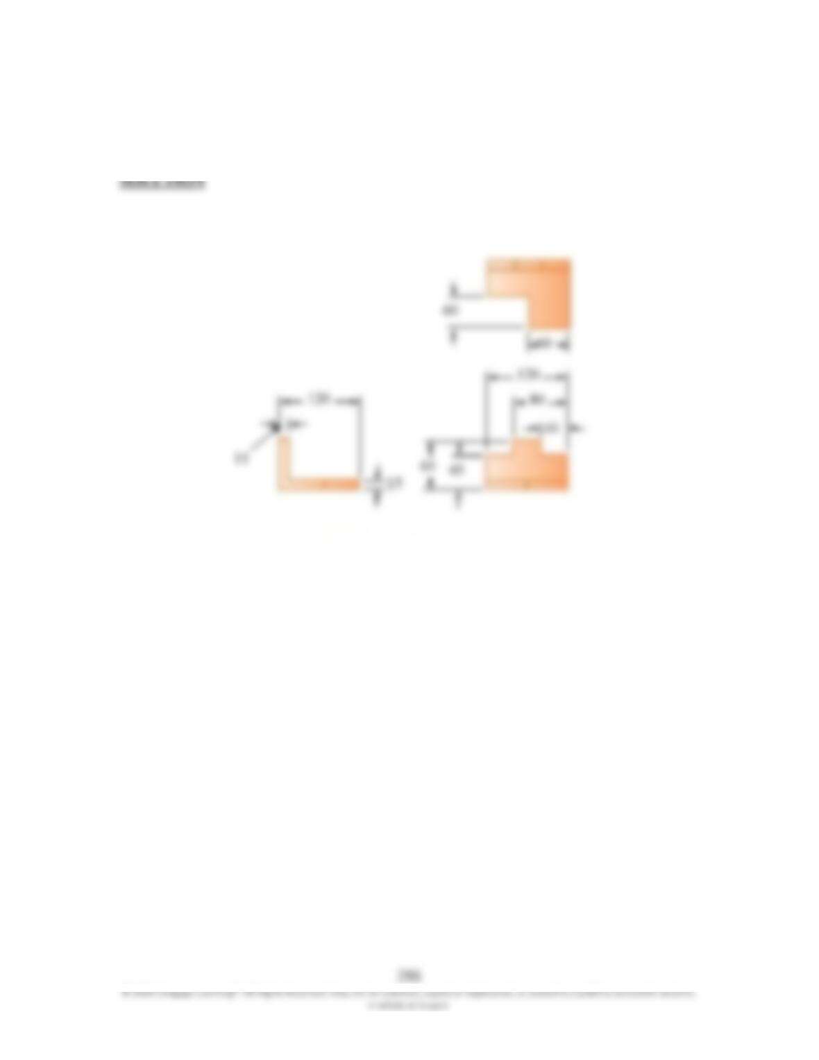
16.28 For Problems 16.24 through 16.28, using the rules discussed in this chapter, show
the dimensions of the views shown.
16.29 For Problems 16.29 through 16.32, show the dimensions of the object on its
orthographic views.
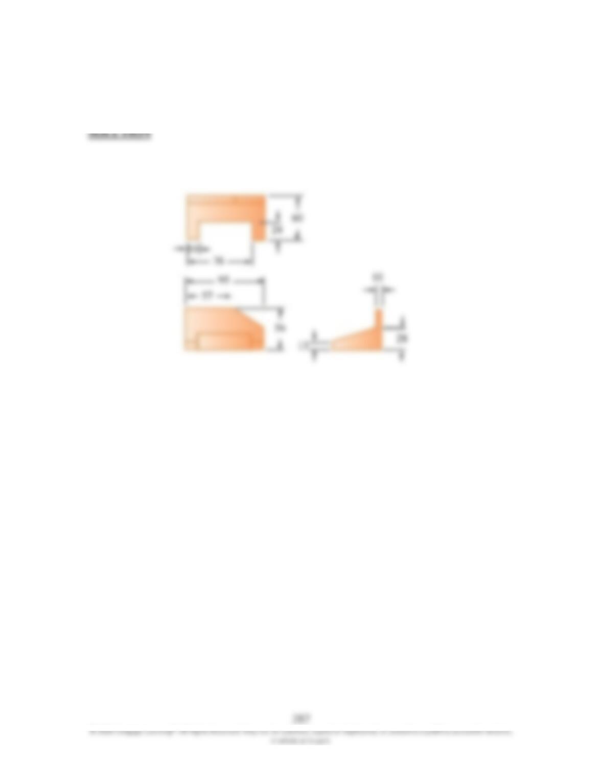
16.30 For Problems 16.29 through 16.32, show the dimensions of the object on its
orthographic views.
16.31 For Problems 16.29 through 16.32, show the dimensions of the object on its
orthographic views.
289
16.32 For Problems 16.29 through 16.32, show the dimensions of the object on its
orthographic views.
Problem 16.4.
2.00
0.50
5.00
0.75
4×
φ
0.296 Thru
290
16.40 Follow the steps discussed in Section 16.1 and draw the isometric view for
Problem 16.6.
Height
2
3
4
291
© 2020 Cengage Learning®. All Rights Reserved. May not be scanned, copied or duplicated, or posted to a publicly accessible website,
in whole or in part.
SOLUTION
Problem 16.7.
Height
2
3
4
292
© 2020 Cengage Learning®. All Rights Reserved. May not be scanned, copied or duplicated, or posted to a publicly accessible website,
in whole or in part.
SOLUTION
16.42 Follow the steps discussed in Section 16.1 and draw the isometric view for
Problem 16.11.
Height
2
3
4
293
© 2020 Cengage Learning®. All Rights Reserved. May not be scanned, copied or duplicated, or posted to a publicly accessible website,
in whole or in part.
SOLUTION
Problem 16.13.
Height
2
3
4
294
© 2020 Cengage Learning®. All Rights Reserved. May not be scanned, copied or duplicated, or posted to a publicly accessible website,
in whole or in part.
SOLUTION
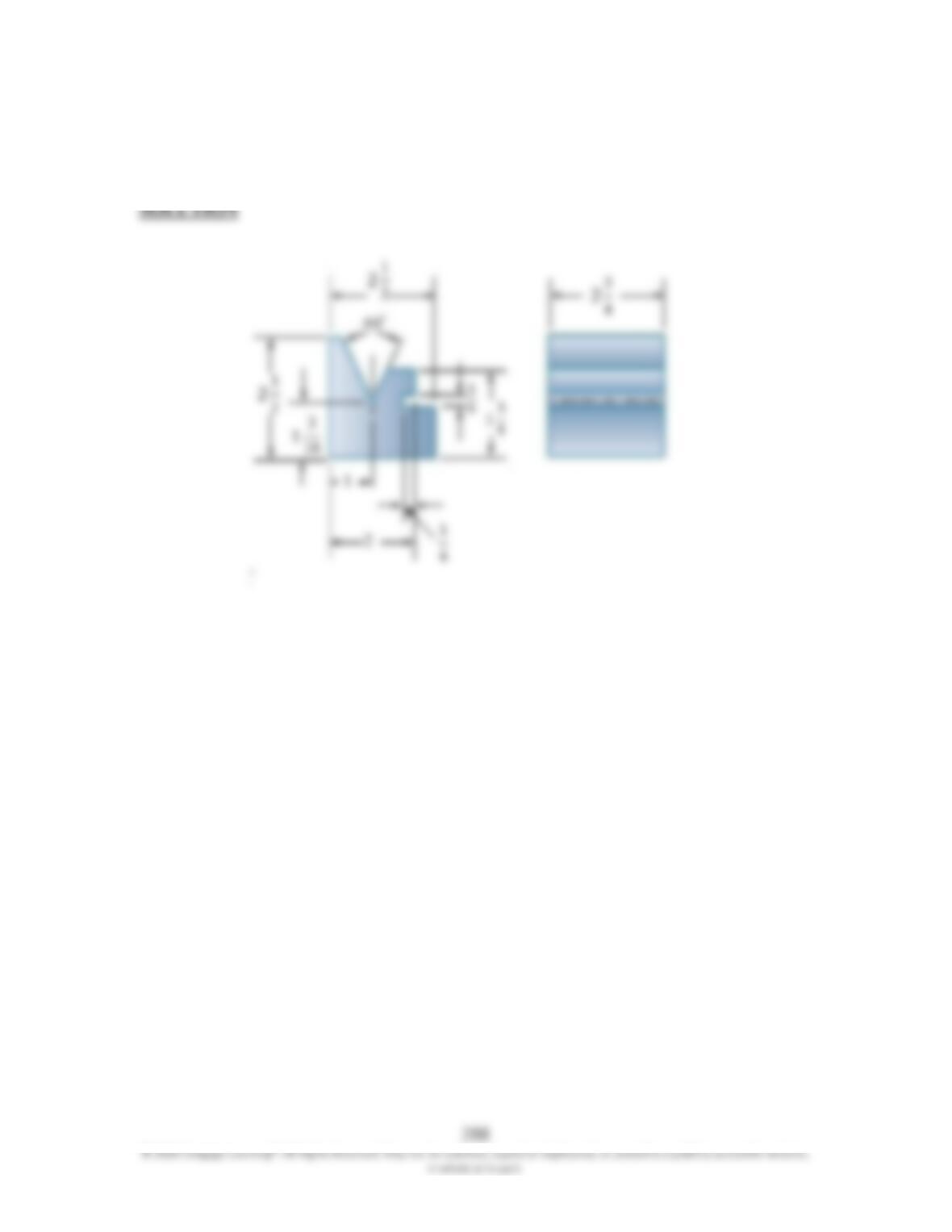
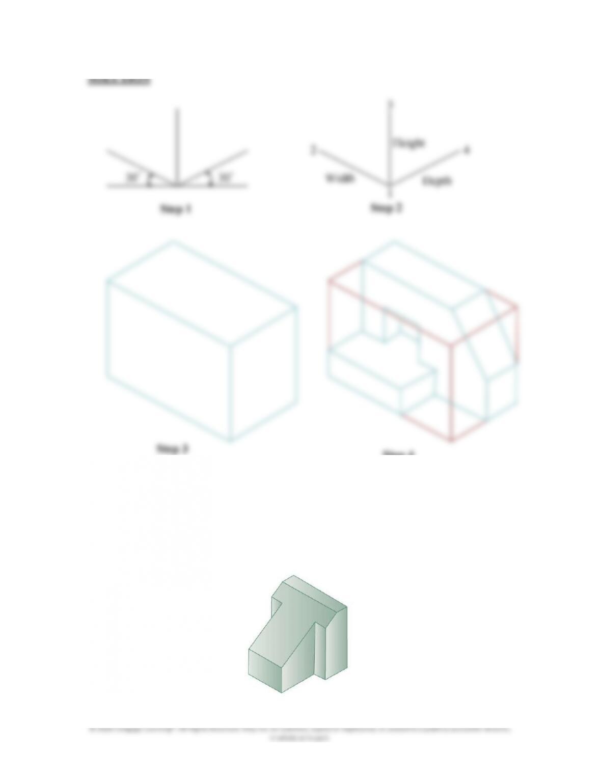
16.44 For Problems 16.44 through 16.48, discuss how you would create the solid model
of the given objects. See Example 16.5 to better understand what you are being
asked to do.
SOLUTION
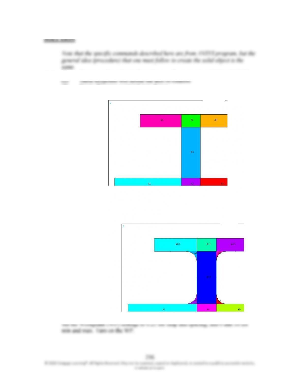
Note that the specific commands described here are from ANSYS program, but the
general idea (procedure) that one must follow to create the solid object is the
same.
30°
30°
Step 1 Step 2
Height
Width Depth
1
2
3
4
Step 3 Step 4
295
1) Create the areas that make up the profile. Add them together.
2) Extrude in the –Z-direction by 6.0 in.
5) On the active workplane create two solid cylinders of length 0.125 at location
where the holes are.
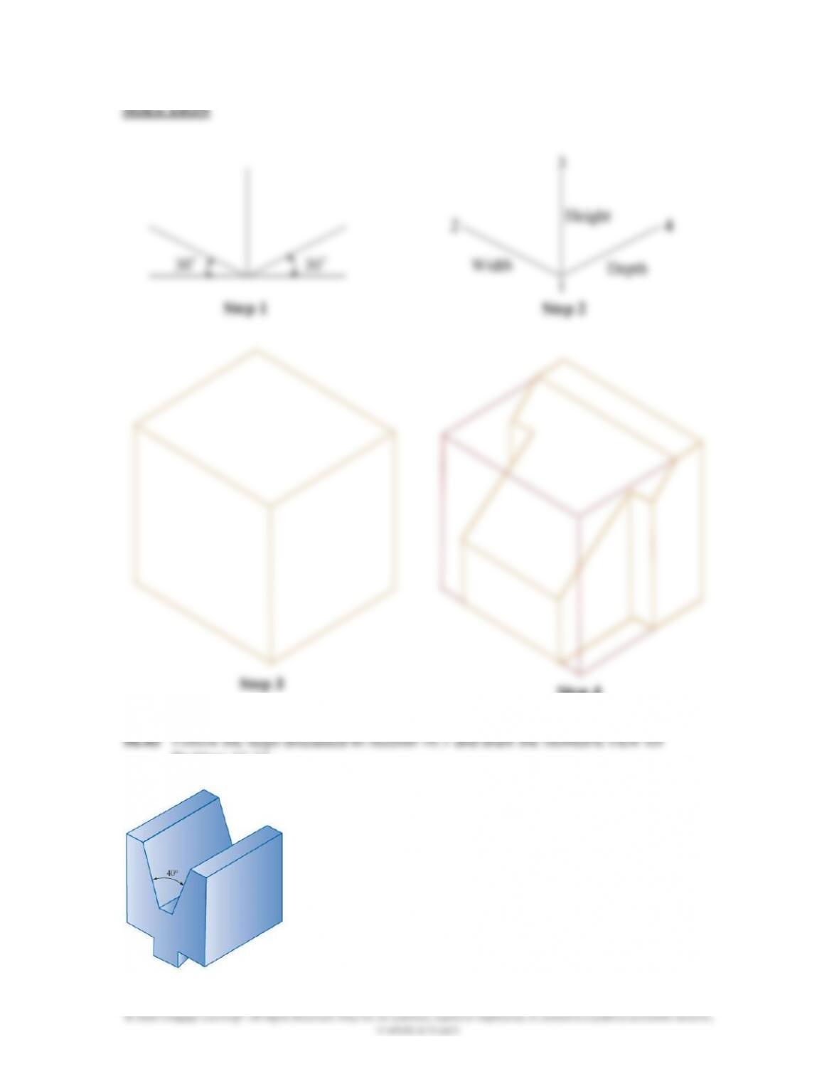
16.45 For Problems 16.44 through 16.48, discuss how you would create the solid model
of the given objects. See Example 16.5 to better understand what you are being
asked to do.
x
z
y
296
© 2020 Cengage Learning®. All Rights Reserved. May not be scanned, copied or duplicated, or posted to a publicly accessible website,
in whole or in part.
SOLUTION
Note that the specific commands described here are from ANSYS program, but the
general idea (procedure) that one must follow to create the solid object is the
same.
(1) Create two keypoints in the active coordinate system at 0,0,0 and 10,0,0.
(3) Create the cross-sectional area shown.
Note that you need to create the smaller areas so that you can create the line fillets
later. Glue the areas and create the line fillets. Using arbitrary area command,
create the fillet areas.
297
© 2020 Cengage Learning®. All Rights Reserved. May not be scanned, copied or duplicated, or posted to a publicly accessible website,
in whole or in part.
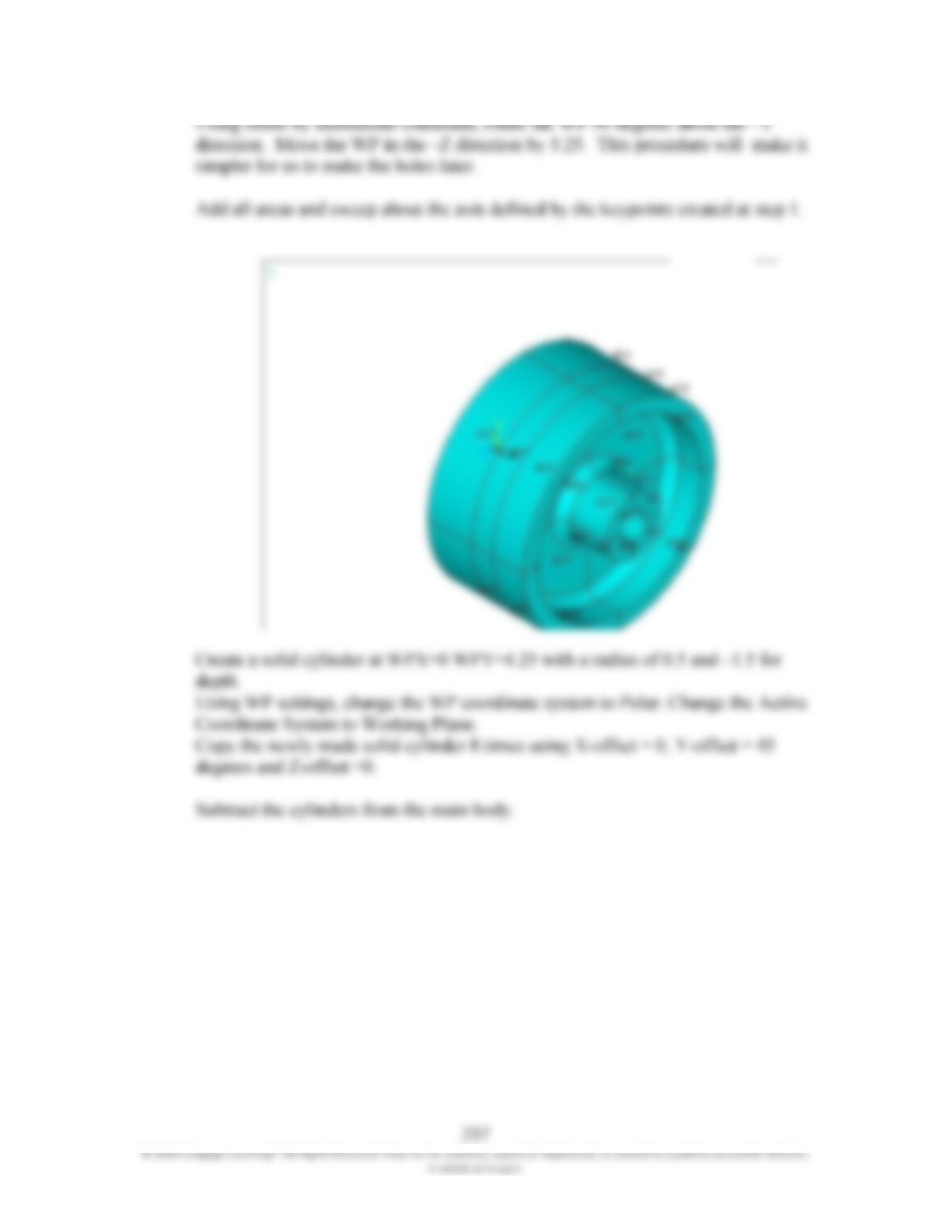
Using offset by increments command, rotate the WP 90 degrees about the –Y
direction. Move the WP in the –Z direction by 5.25. This procedure will make it
simpler for us to make the holes later.
Add all areas and sweep about the axis defined by the keypoints created at step 1.
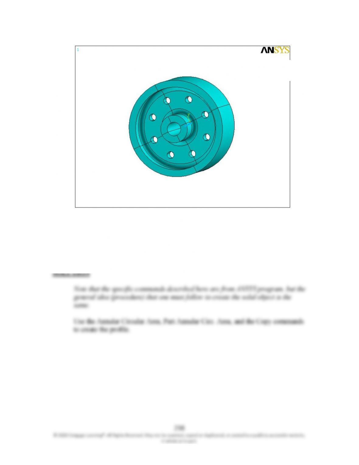
Create a solid cylinder at WPX=0 WPY=4.25 with a radius of 0.5 and –1.5 for
depth.
Using WP settings, change the WP coordinate system to Polar. Change the Active
Coordinate System to Working Plane.
Copy the newly made solid cylinder 8 times using X-offset = 0, Y-offset = 45
degrees and Z-offset =0.
Subtract the cylinders from the main body.
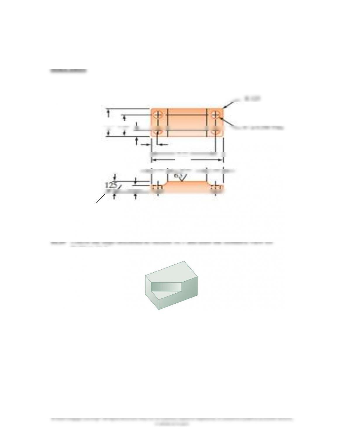
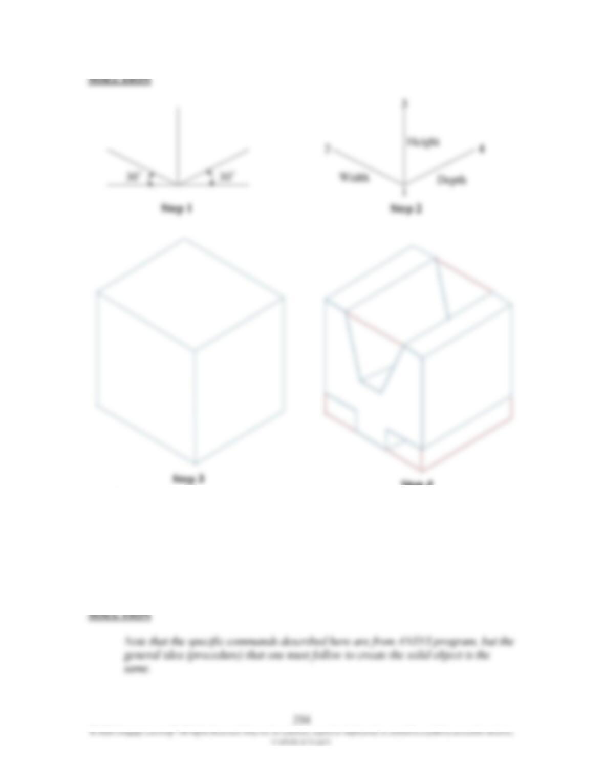
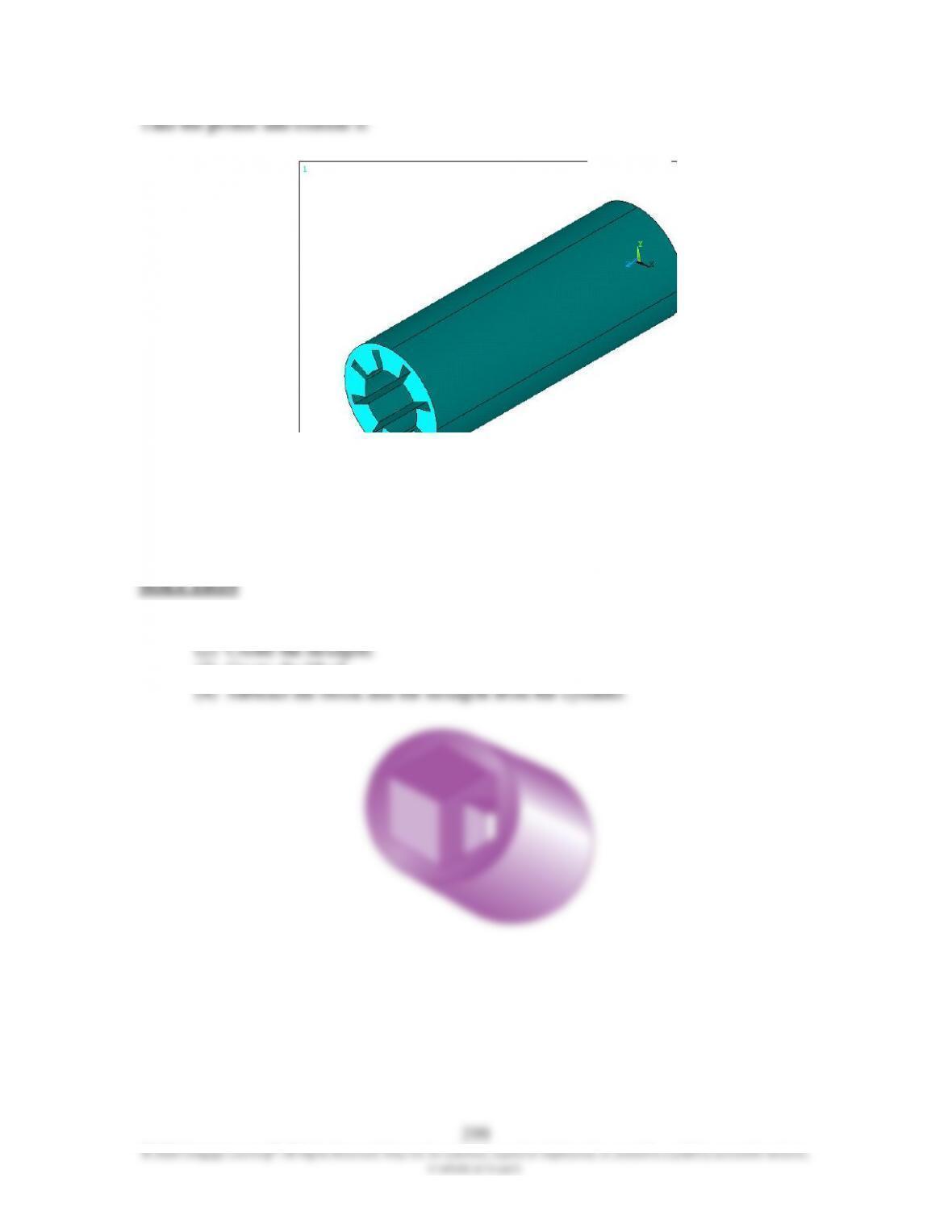
16.46 For Problems 16.44 through 16.48, discuss how you would create the solid model
of the given objects. See Example 16.5 to better understand what you are being
asked to do.
299
© 2020 Cengage Learning®. All Rights Reserved. May not be scanned, copied or duplicated, or posted to a publicly accessible website,
in whole or in part.
Take the profile and extrude it.
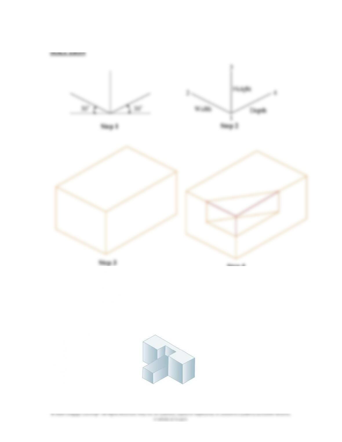
16.47 For Problems 16.44 through 16.48, discuss how you would create the solid model
of the given objects. See Example 16.5 to better understand what you are being
asked to do.
(1) Create the cylinder.
(3) Create the block.
300
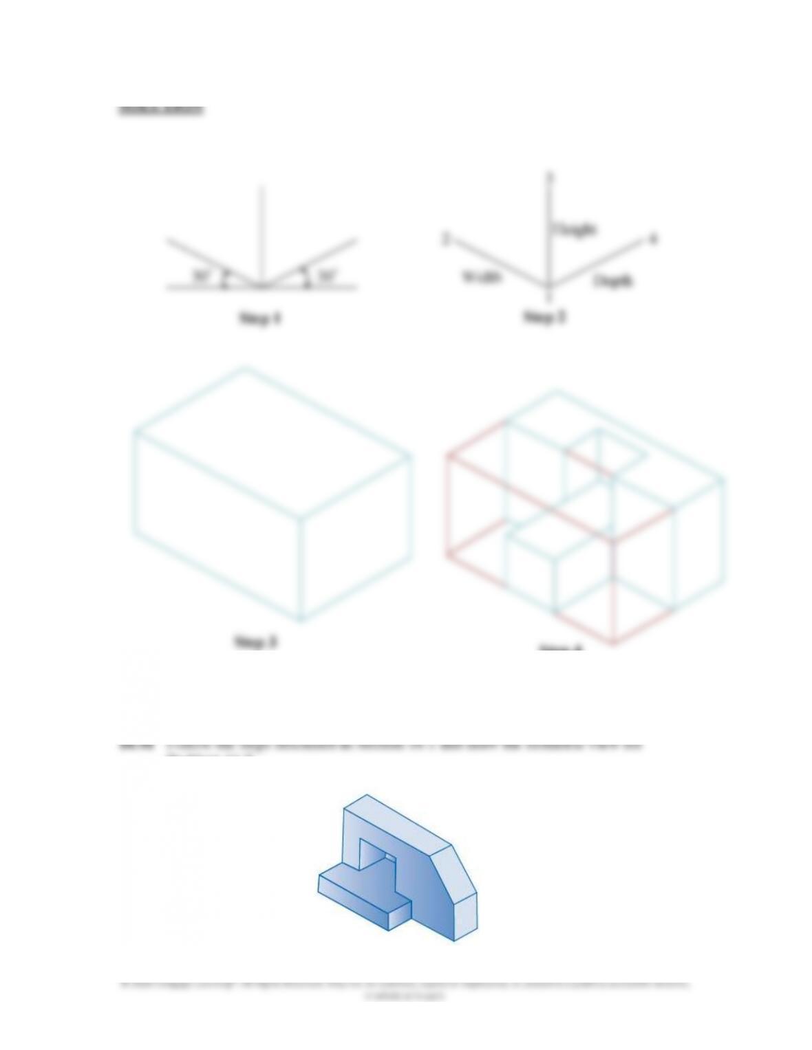
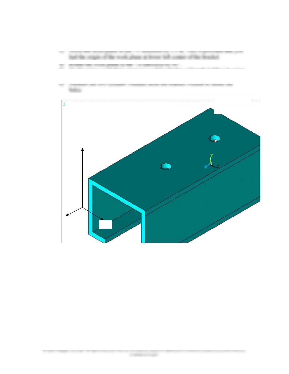
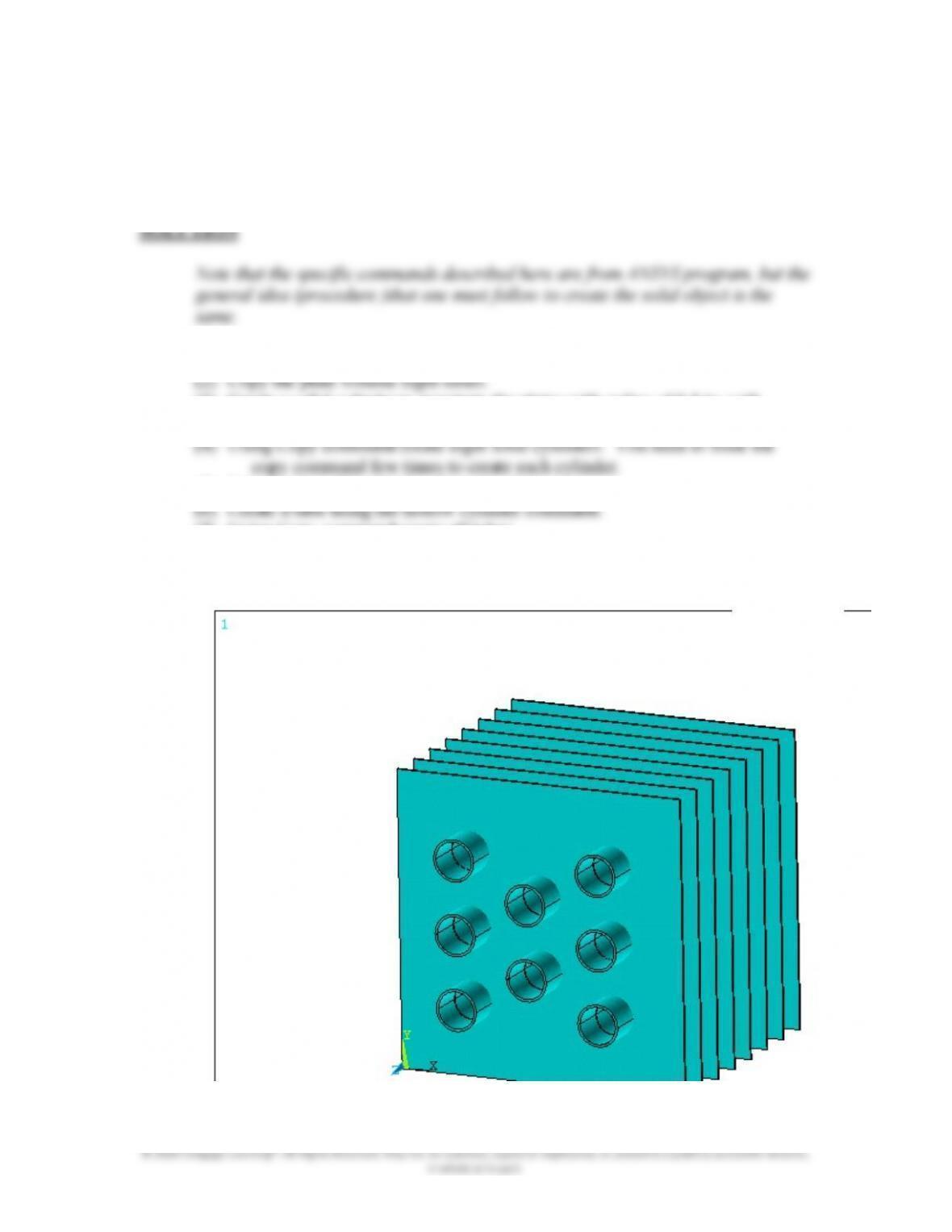
16.48 For Problems 16.44 through 16.48, discuss how you would create the solid model
of the given objects. See Example 16.5 to better understand what you are being
asked to do.
(1) Create one of the plates using the BLOCK primitive.
(3) Create a solid cylinder to penetrate the plates with radius of 0.5 in. with
its center at 2.5 in., 2.5 in, 0.
(5) Subtract the solid cylinders from the plates.
(7) Using Copy command create all tubes.
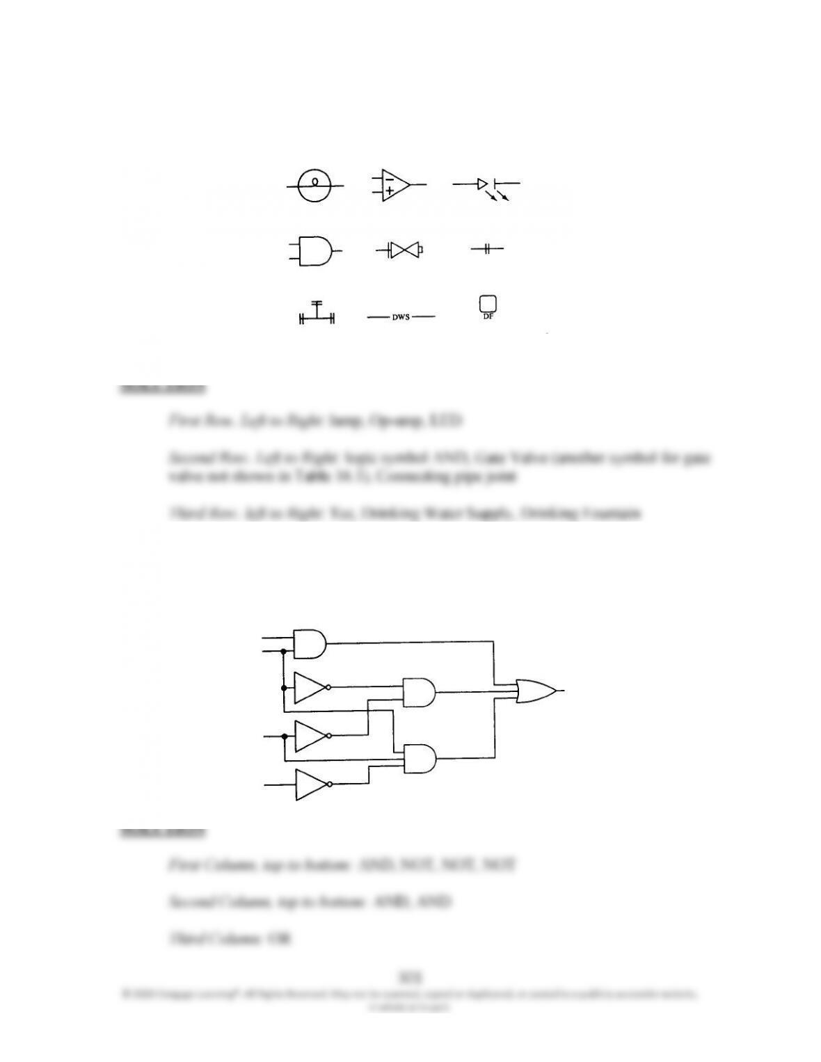
16.49 Using Table 16.1, identify the engineering symbols shown in the accompanying
figure.
16.50 Using Table 16.1, identify the components of the logic system shown in the
accompanying figure.