1
CHAPTER 1. MATERIALS ENGINEERING CONCEPTS
1.3. A = 0.6 x 0.6 = 0.36 in2
V= 0.945 GPa
1.5. A = Sd2/4 = 28.27 in2
V P / A = -150,000 / 28.27 in2= -5.31 ksi
E = VH = 8000 ksi
1.6. A = Sd2/4 = 0.196 in2
V P / A = 2,000 / 0.196 in2= 10.18 ksi (Less than the yield strength. Within the elastic
region)
2
1.7. L
x =30 mm, Ly= 60 mm, Lz= 90 mm
Vx=Vy=Vz=V= 100 MPa
Hx= [Vx–Q(Vy+Vz) ] /E
Hx= [100 x 106– 0.333 (100 x 106+ 100 x 106)] / 70 x 109= 4.77 x 10-4 =Hy=Hz=H
1.8. L
x =4 in, Ly= 4 in, Lz= 4 in
Hx= [Vx–Q(Vy+Vz) ] /E
Hx= [15 – 0.49 (15 + 15)] / 1000 = 0.0003 = Hy=Hz=H
‘Lx= Hx Lx= 0.0003 x 15 = 0.0045 in
1.9. H= 0.3 x 10⁻¹⁶ V3
At V= 50,000 psi, H = 0.3 x 10⁻¹⁶ (50,000)3= 3.75 x 10⁻³ in./in.
‘
‘
V
H
50 000
375 10 3
,
.x
d
d
H
V
0.9 x 10⁻¹⁶ V2
d
H
dx
H
225 10
7
.
3
1.11. Hlateral =
1
1025.3
4
x
= -3.25 x 10⁻⁴ in./in.
210
3
x
H
axial
x
110
3
1.12. Haxial = 0.05 / 50 = 0.001 in./in.
1.13. L = 380 mm
D = 10 mm
P = 24.5 kN
V= P/A = P/Sr2
V= 24,500 N/ S(5 mm) 2= 312,000 N/mm2= 312 Mpa
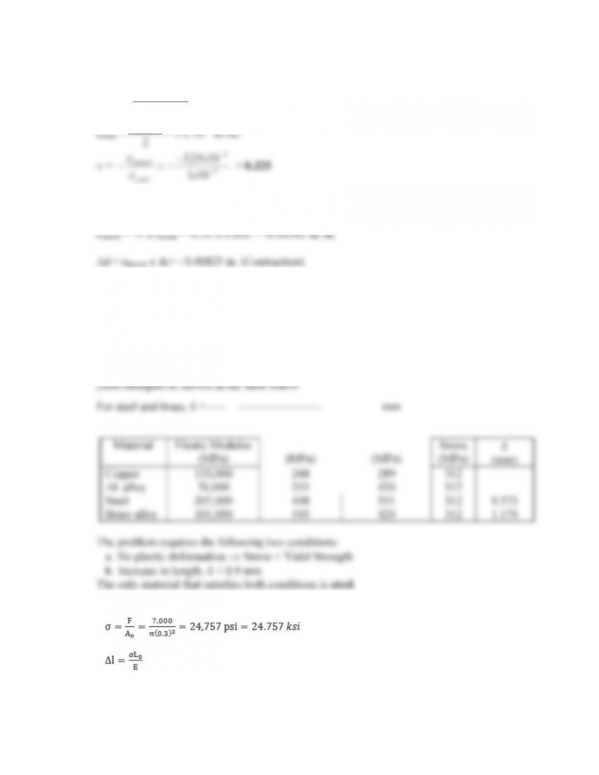
The copper and aluminum can be eliminated because they have stresses larger than their
1.14.
This stress is less than the yield strengths of all metals listed.
4
Material
E (ksi)
Yield Strength (ksi)
Tensile Strength (ksi)
‘
L (in.)
Steel alloy 1
26,000
125
73
0.014
Steel alloy 2
29,000
58
36
0.013
Titanium alloy
16,000
131
106
0.023
Copper
17,000
32
10
0.022
Only the steel alloy 1 and steel alloy 2 have elongation less than 0.018 in.
1.15
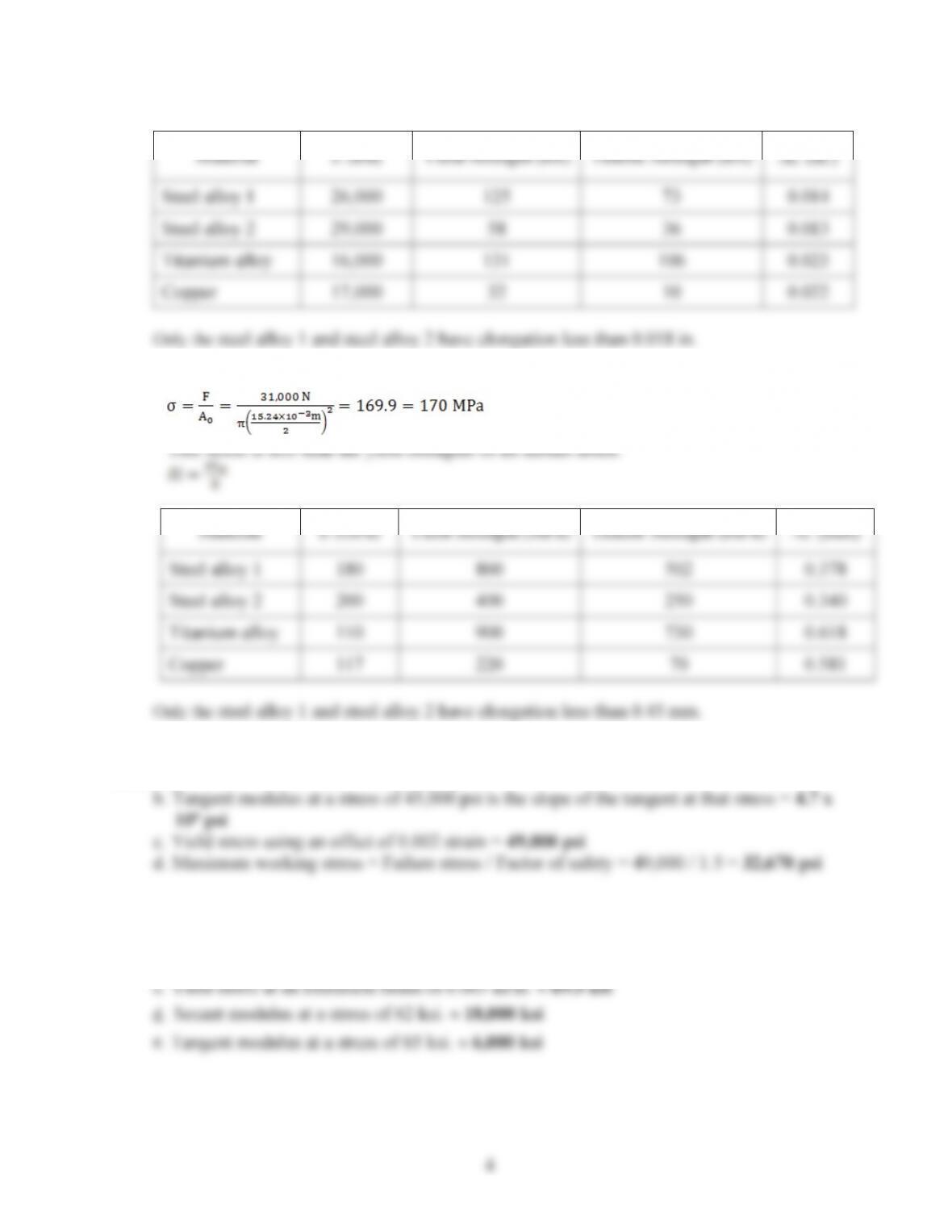
1.16. a. E = V/H= 40,000 / 0.004 = 10 x 106psi
1.17.D Modulus of elasticity within the linear portion = 20,000 ksi.
EYield stress at an offset strain of 0.002 in./in. |70.0 ksi
5
1.18.a. Modulus of resilience = the area under the elastic portion of the stress strain curve =
½(50 x 0.0025) |0.0625 ksi
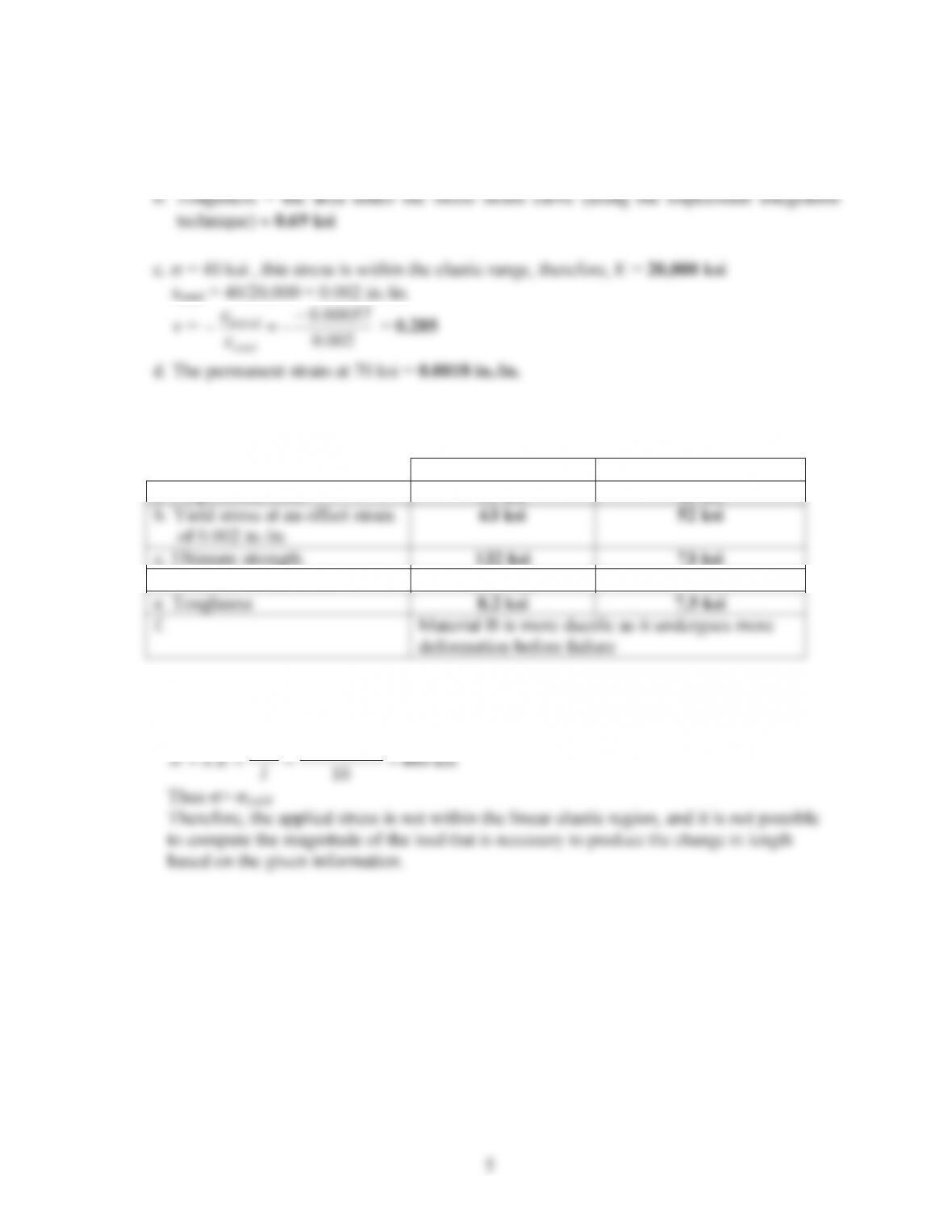
1.19.
Material A
Material B
a. Proportional limit
51 ksi
40 ksi
b. Yield stress at an offset strain
of 0.002 in./in.
63 ksi
52 ksi
c. Ultimate strength
132 ksi
73 ksi
d. Modulus of resilience
0.065 ksi
0.07 ksi
e. Toughness
8.2 ksi
7.5 ksi
f.
Material B is more ductile as it undergoes more
deformation before failure
1.20. Assume that the stress is within the linear elastic range.
000,163.0.
E
G
6
1.21. Assume that the stress is within the linear elastic range.
000,1056.7.
E
G
1.22. At V= 60,000 psi, H=V/ E = 60,000 / (30 x 106) = 0.002 in./in.
a. For a strain of 0.001 in./in.:
1.23. D Slope of the elastic portion = 600/0.003 = 2×10⁵MPa
Slope of the plastic portion = (800-600)/(0.07-0.003) = 2,985 MPa
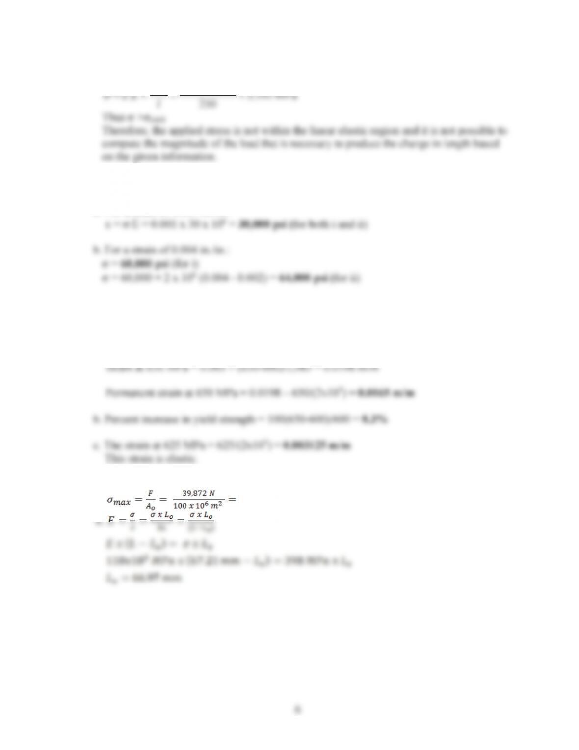
1.24a. 0.000399 Pa = 398 MPa
7
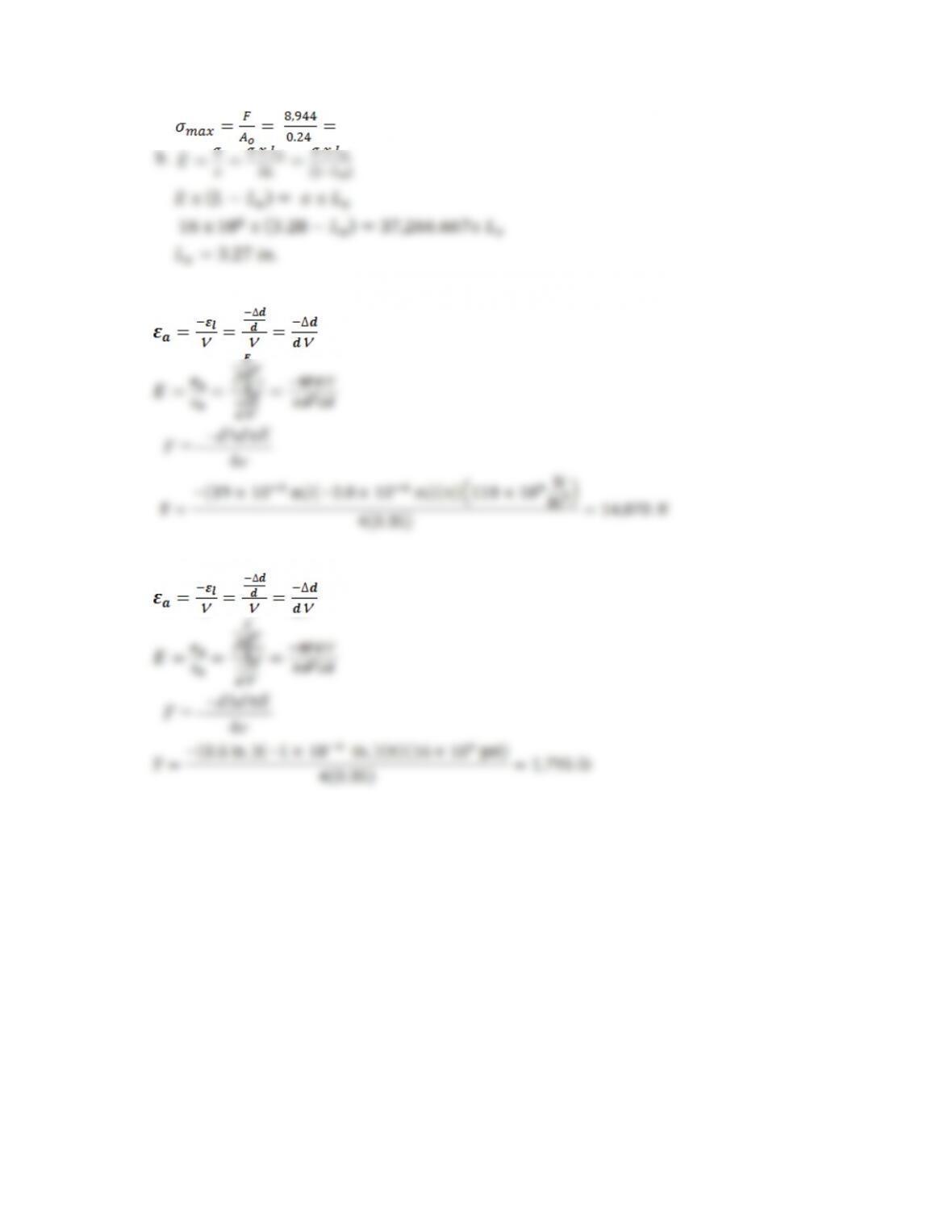
1.25 a. 37,266.667 psi
1.26
Q
4
= E
dd
–
F
S‘
1.27
Q
4
= E
dd
–
F
S‘
1.28. See Sections 1.2.3, 1.2.4 and 1.2.5.
8
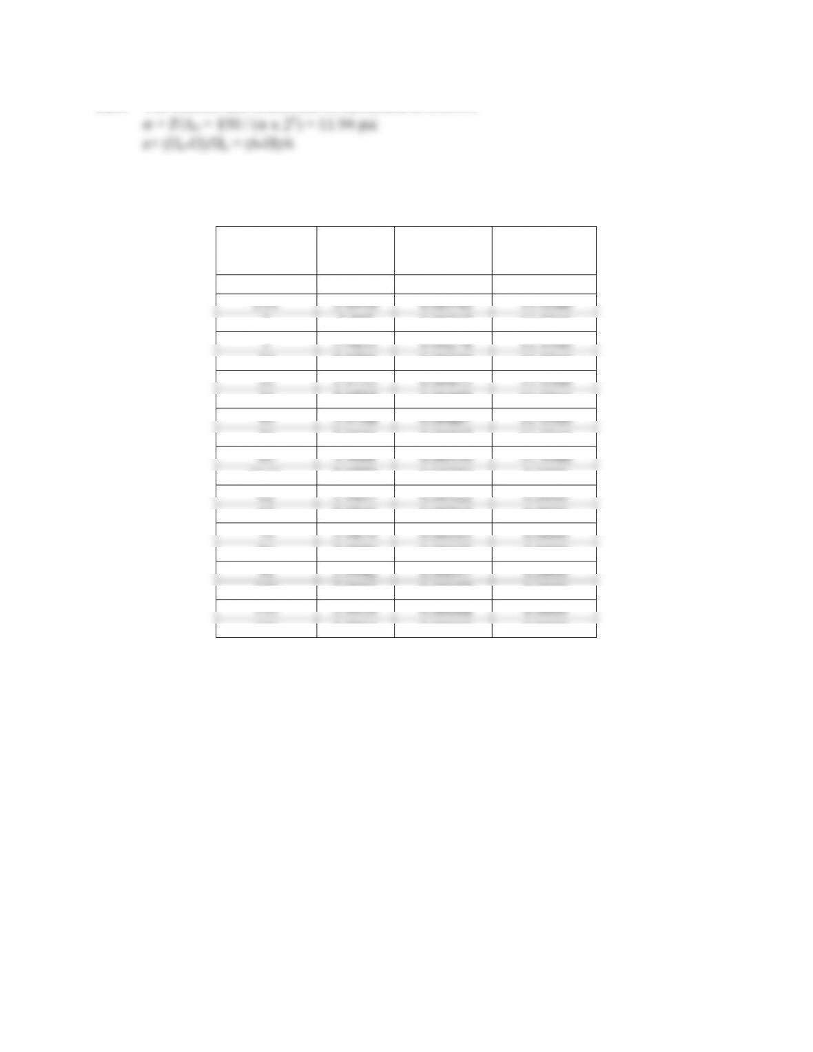
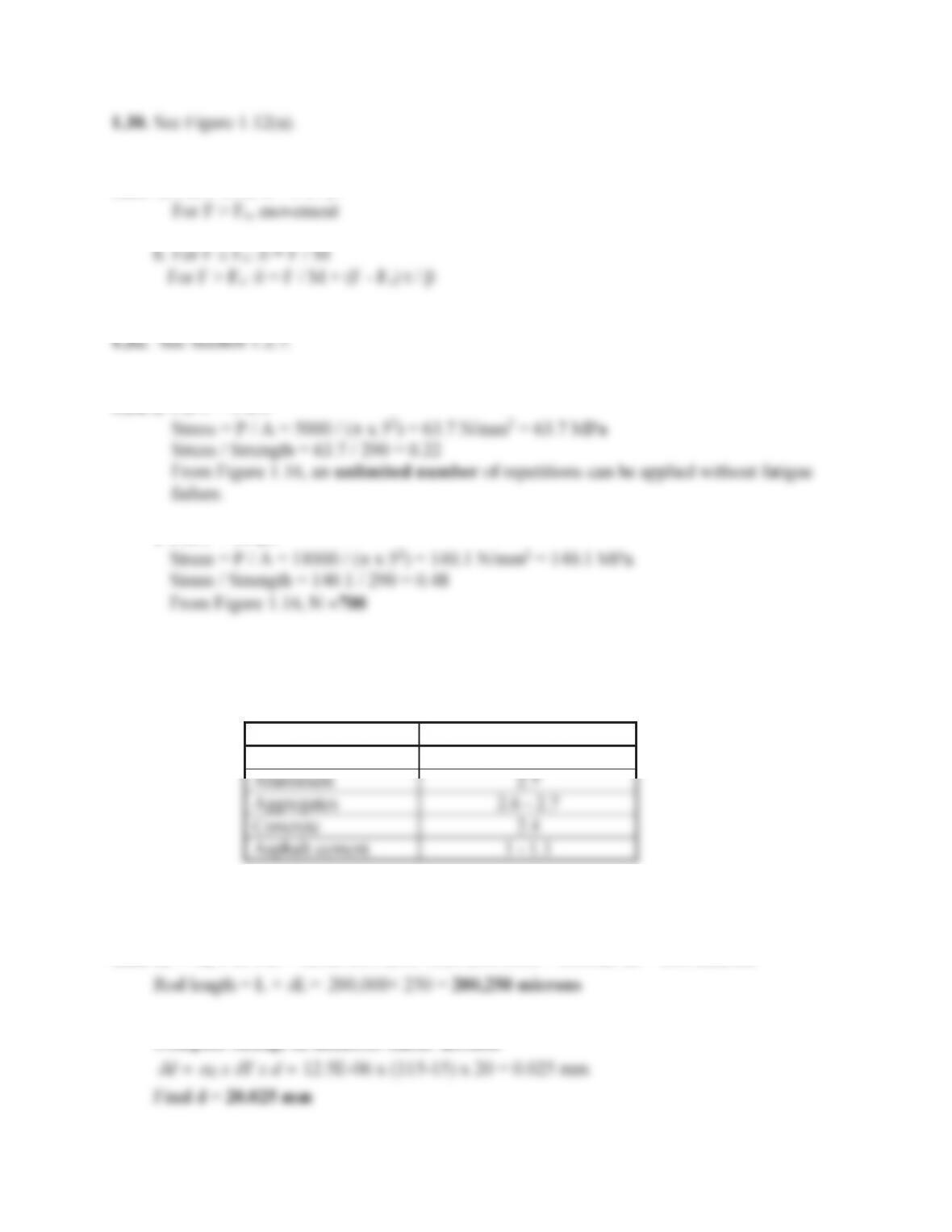
1.29. The stresses and strains can be calculated as follows:
The stresses and strains are shown in the following table:
Time
(min.)
H
(in.)
Strain
(in./in.)
Stress
(psi)
0
6
0.00000
11.9366
0.01
5.9916
0.00140
11.9366
2
5.987
0.00217
11.9366
5
5.9833
0.00278
11.9366
10
5.9796
0.00340
11.9366
20
5.9753
0.00412
11.9366
30
5.9725
0.00458
11.9366
40
5.9708
0.00487
11.9366
50
5.9696
0.00507
11.9366
60
5.9688
0.00520
11.9366
60.01
5.9772
0.00380
0.0000
62
5.9807
0.00322
0.0000
65
5.9841
0.00265
0.0000
70
5.9879
0.00202
0.0000
80
5.9926
0.00123
0.0000
90
5.9942
0.00097
0.0000
100
5.9954
0.00077
0.0000
110
5.9959
0.00068
0.0000
120
5.9964
0.00060
0.0000
9
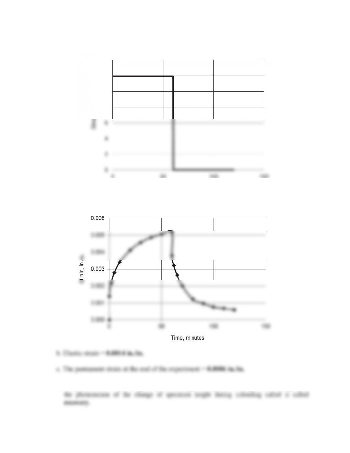
a. Stress versus time plot for the asphalt concrete sample
7LPHPLQXWHV
d.
The phenomenon of the change of specimen height during static loading is called
creep
while
10
1.31a. For F dFo:G= F.t / E
1.34. a. For P = 5 kN
b. For P = 11 kN
1.35See Section 1.2.8.
1.36.
Material
Specific Gravity
Steel
7.9
Aluminum
2.7
Aggregates
2.6 – 2.7
Concrete
2.4
Asphalt cement
1 – 1.1
1.37See Section 1.3.2.
1.38.
G
L =
D
Lx
G
T x L = 12.5E-06 x(115-15) x200/1000 = 0.00025 m = 250 microns
Compute change in diameter linear method
11
Compute change in diameter volume method
There is no stress acting on the rod because the rod is free to move.
1.39. Since the rod is snugly fitted against two immovable nonconducting walls, the length of the
rod will not change, L = 200 mm
1.40. a. The change in length can be calculated using Equation 1.9 as follows:
b. The tension load needed to return the length to the original value of 4 meters can be
calculated as follows:
1.41. If the bar was fixed at one end and free at the other end, the bar would have contracted and
no stresses would have developed. In that case, the change in length can be calculated
using Equation 1.9 as follows.
1.43. See Section 1.7.
12
1.44. See Section 1.7.1
1.45. Ho:P
t
32.4 MPa
To=
x
P
=-3
1.46. Ho:P
t
5,000 psi
H1:P5,000 psi
1.47.
psi
x
n
x
x
ii
n
ii
25.698,5
20
965,113
20
20
11
¦
¦
x
xx
ii
n
ii
)25.5698(
)(
2
/
1
20
1
2
2
/
1
1
2
¸
¸
·
¨
¨
§
¸
¸
·
¨
¨
§
¦¦