24-15
24.15 (a) Pump and system curves:
46.1
hm50
hm73
hm 73 3
3
3
max
v
46% scale-up
Heat Exchanger:
lm
ss
TUAQ
mQ
mQ
20% scale-up
Vaporizer limits scale-up since Tmax for steam is 160 C.
(b) NPSHAPtank gh PfP*
24-16
24.16 Drying Oil Facility
Trouble Shooting
(a) Noisy pump
We can do calculations, but these components are not volatile, so the most likely
pump can be fixed.
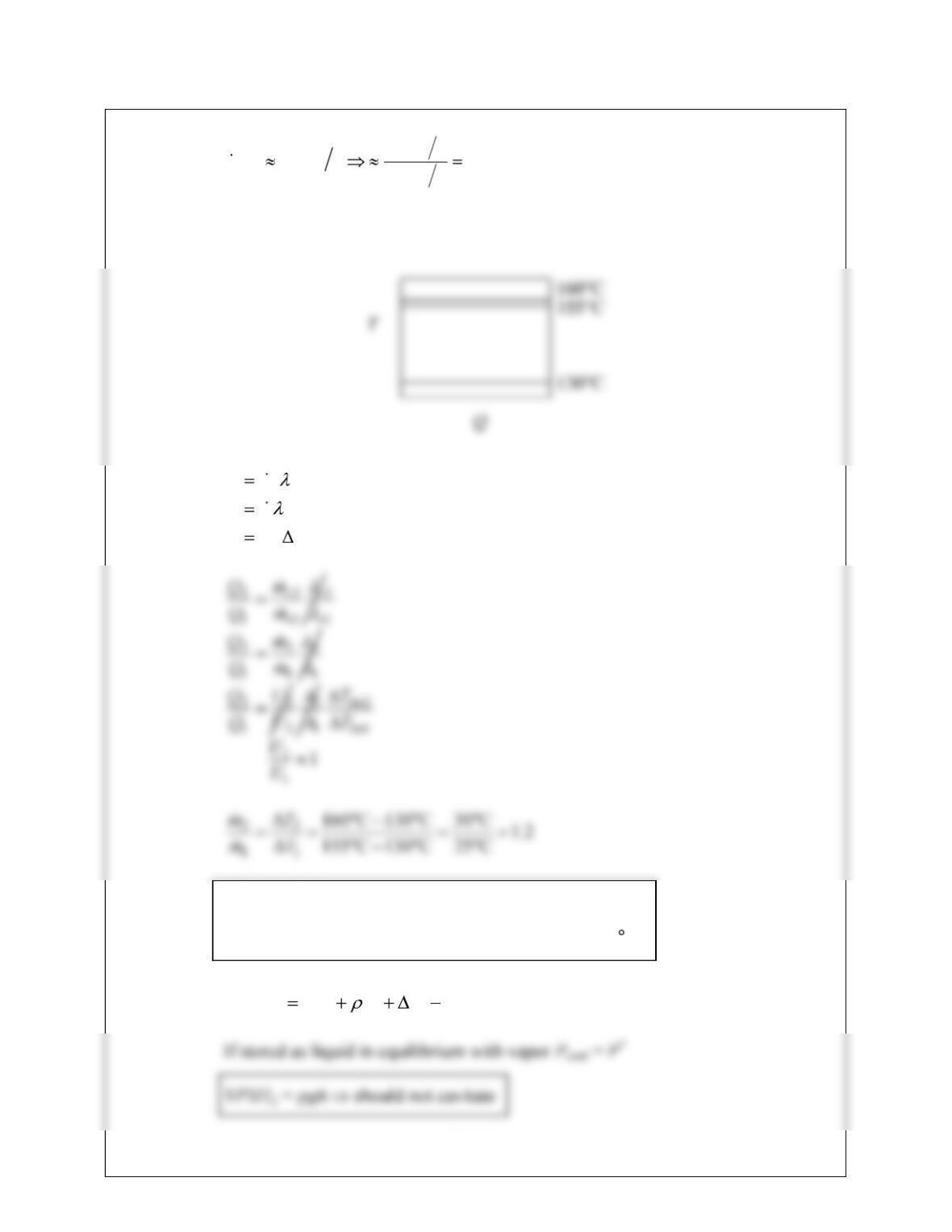
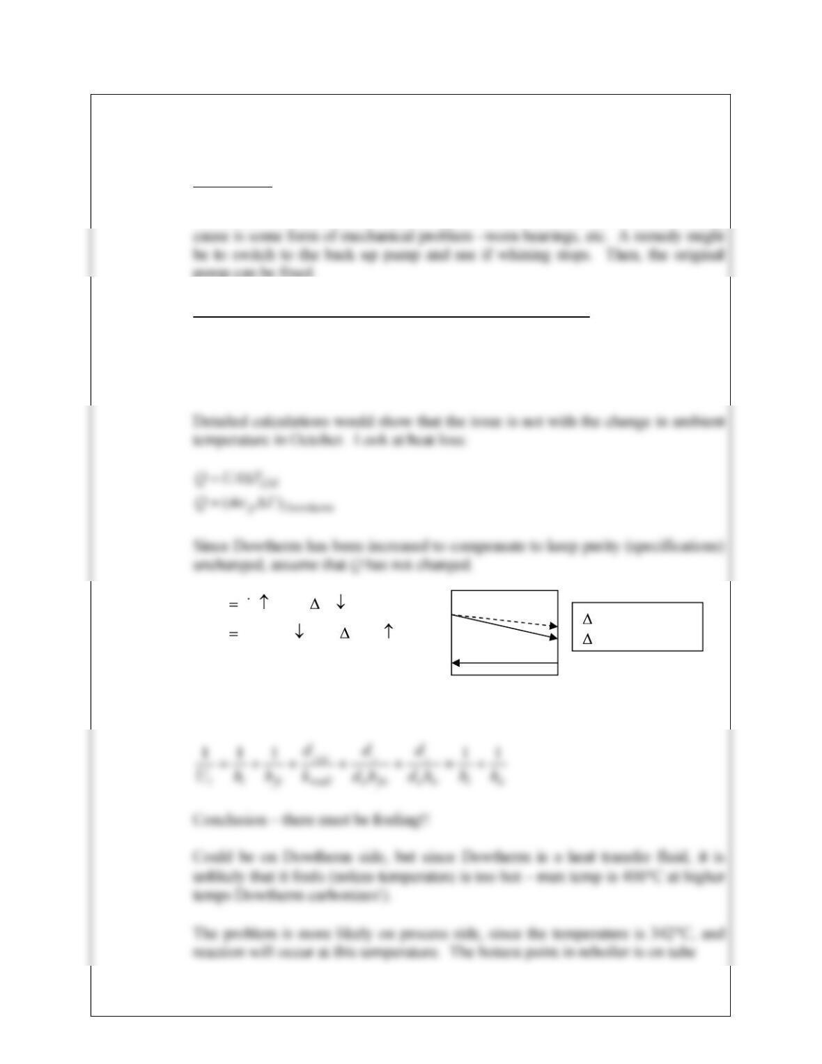
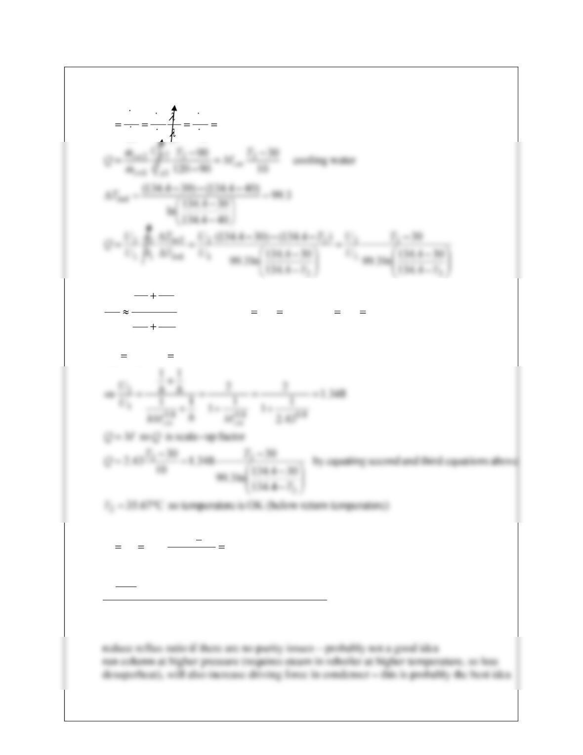
(b) Problem with T-501 and the increased Dowtherm A flowrate.
Although a drop in ambient temperature might have an effect, it would be small.
As temperature drops, heat loss increases and inlet cooling water temperature
drops.
( ) ( ) ( ) ( )
( ) ( ) ( ) ( )
p
LM
Q c m c c T
Q c U must A c T
But U will increase because the mass flow of Dowtherm has increased therefore
something in U must have decreased to compensate!
T decreases
T
LM
increases
24-17
24.16 (contd)
walls where reaction will occur. Note that there is not much DO here, so gum
formation will be slow, but only a small amount is needed for film heat transfer to
decrease.
Alternatively, the filter may not be working properly, so the gum content in
Stream 7 should be checked.
How to solve the problem?
a) If filter is a problem recommend regular samples of Stream 7 to identify
when gum breakthrough occurs.
(c) ACO Feed problem
There are two issues:
First, the control scheme is wrong. The control valve should be using the level
control of V-501 as its signal. As it is now, the flow into V-501 will fluctuate
24.16 (contd)
A solution is to heat feed tank and also heat trace the supply line. The feed tank
may have a steam heater that no one has turned on or maybe it is malfunctioning.
The line is already insulated, but for extended periods of time this will not help.
The supply line could be retro-fitted with larger diameter pipe.
(d) Steam venting from E-506
Most probable cause is the addition of the extra pipe and elbows connecting the
exchanger to the low-pressure steam header. This extra pipe causes additional
24.17 Scale Down
The equipment that must be considered is as follows:
24-19
24.18
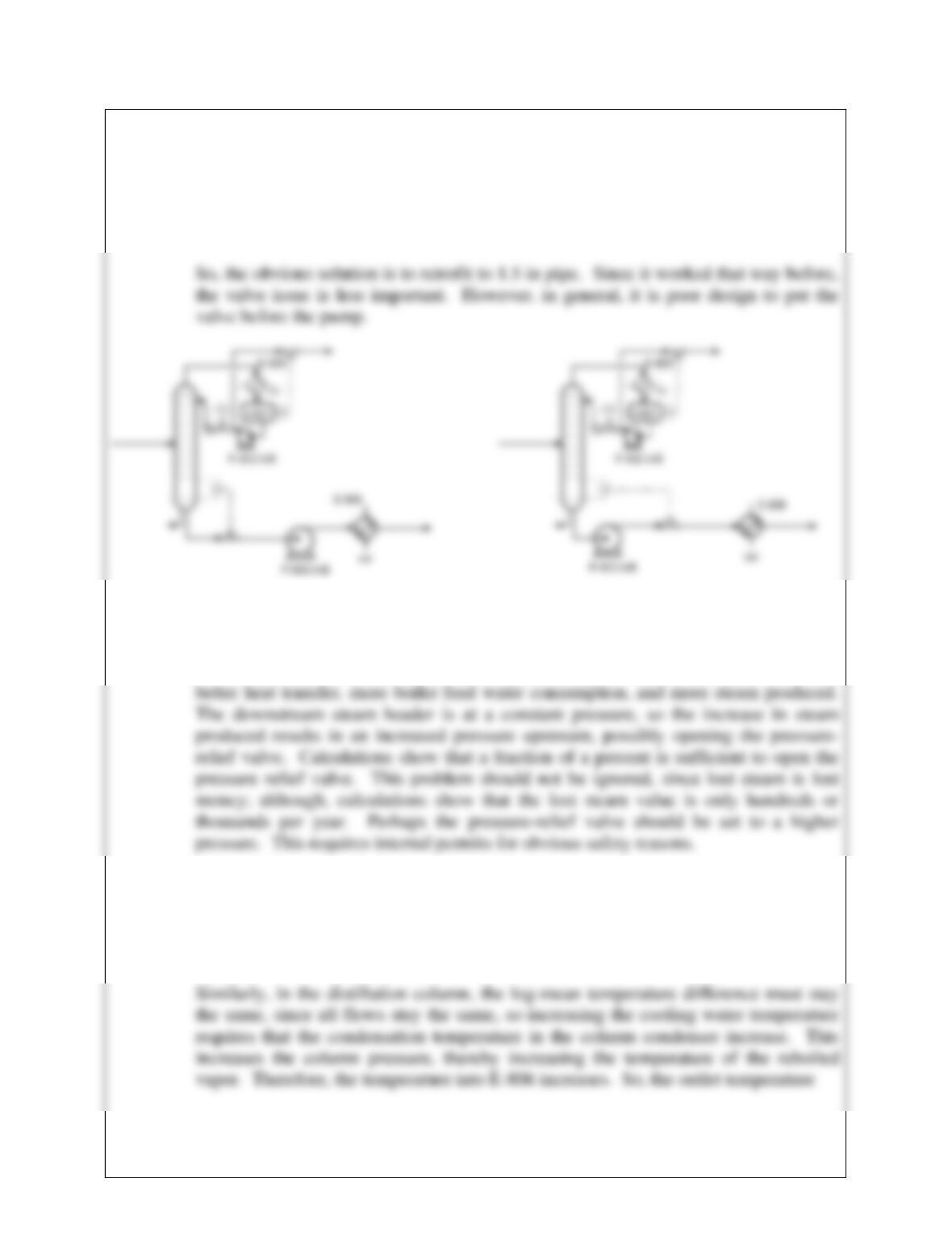
(a) By replacing the 1.5 in pipe with 1 in pipe, the pressure drop probably induces
cavitation in the pump. Calculations would support this. Also, having the valve
before the pump lowers the pressure, further inducing cavitation (left figure). The
figure on the right is a better design.
(b) Something is happening right after plant start up. Two possibilities come to mind. If
the heat exchanger were designed to include a fouling factor, the tubes would
probably not be fouled upon start up. Another possibility is that the catalyst
deactivates with time, but is at full activity at start up. In either case, there would be
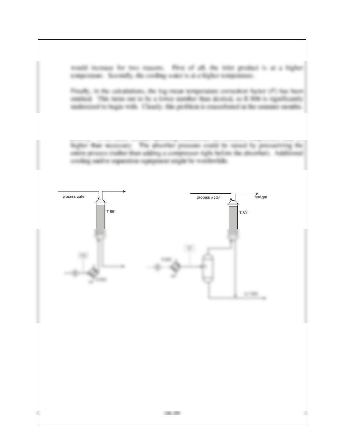
(c) During the summer, warmer cooling water affects several units, specifically the
absorber, the distillation column, and the product cooler. The increased fuel gas rate
supports this because if the temperature in the absorber increases, absorption
equilibrium favors the vapor phase.
24.18 (contd)
(d) Additionally, the following process improvement might be a good idea. The value of
methanol in Stream 12 is about $2 million/yr. Methanol recovery should be a high
priority. Even under normal operating conditions, the absorber temperature may be
Two options for better methanol recovery might be:
24-21
24.19
(a) Fuel gas has increased in order to maintain Stream 2 at 900°F. This is probably due
to a lower HT coefficient on tube side in furnace. During temporary upset, oil would
sit inside tube and radiant furnace walls may have caused coking on the inside surface
of tubes. This means tube walls are hotter now and so this may be a problem in the
long term.
24-22
24.20
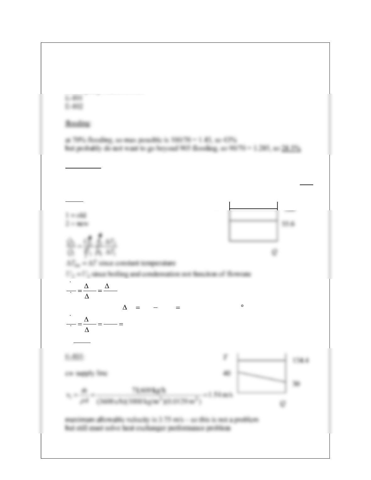
a. potential bottlenecks
flooding
reflux pump characteristics
reflux pump:
77,800/700 = 111.1 m3/h so if maximum flowrate is 149, 149/111.1 = 1.34, so 34%
E-102:
22.2
4.44
4.98
C254at hps since 4.986.155254 possible maximum
4.44
1
2
1
2
2
2
1
2
1
2
T
T
Q
Q
T
T
T
T
Q
Q
so 122%
T
24-23
1 = old
2 = new
38.1
10
3067.35
43.2
condensing since
11
11
condensing process
8.08.0
12
1211
22
11
1
2
1
2
1
2
1
2
1
2
MQ
hMMhh
hhhhhh
hh
hh
U
U
M
m
m
m
m
Q
Q
Q
ii
oooi
oi
oi
so 38%
so, flooding appears to be the limiting bottleneck
b.
24-24
24.21 Note: This is the same problem as 22.19. It may be considered a troubleshooting
problem or a multiple-unit performance problem. The problem that follows is different
but requires a similar analysis.
a.
1 = old
2 = new
use ratios
all resistance on tube side, so 8.0
mU
b.
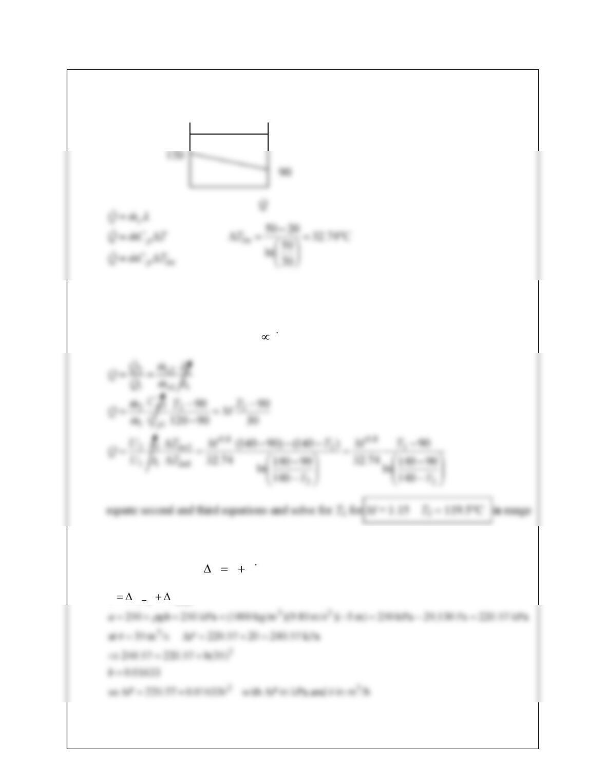
to get system curve 2
vbaP
PPa headds
T
140
24-25
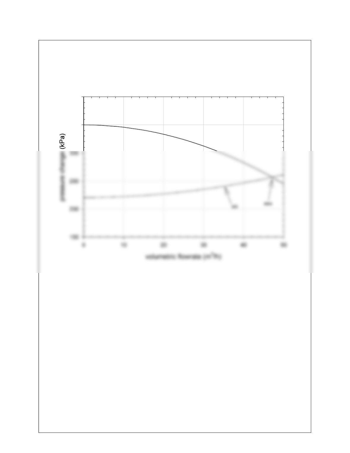
24.21 (contd)
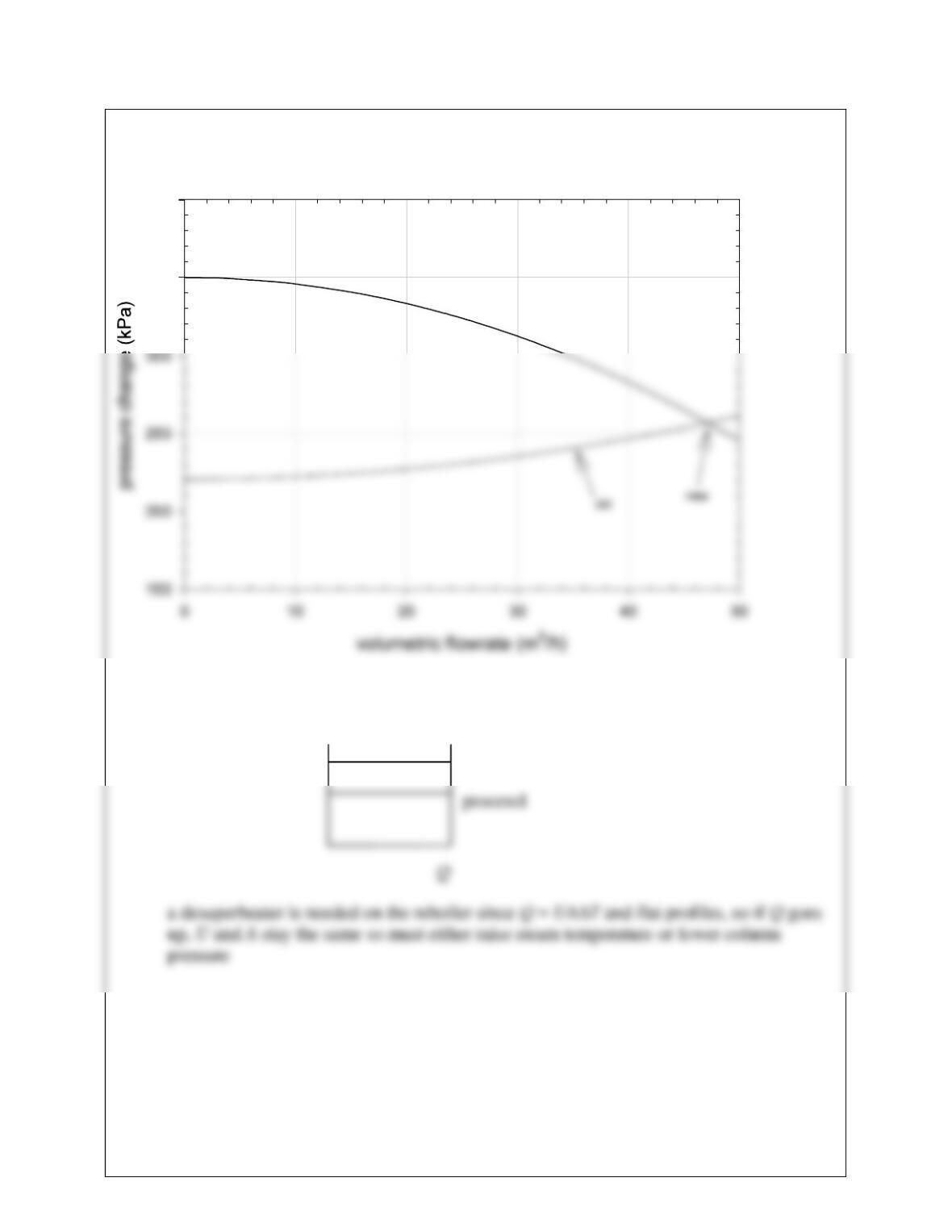
pump-system curve plot
350
400
maximum flowrate about 47 m3/h, desired flowrate is 1.15(35) = 40.25 m3/h no
problem
c.
d.
This is a liquid-phase reaction, so there is no effect of pressure on the reaction rate.
Also, pumps do not change liquid temperature significantly.
T
steam
24-26
24.22
a.
all resistance on tube side, so 8.0
mU
1
2
1
2
1
2
1
2
M
m
m
m
m
Q
Q
Q
s
s
s
s
s
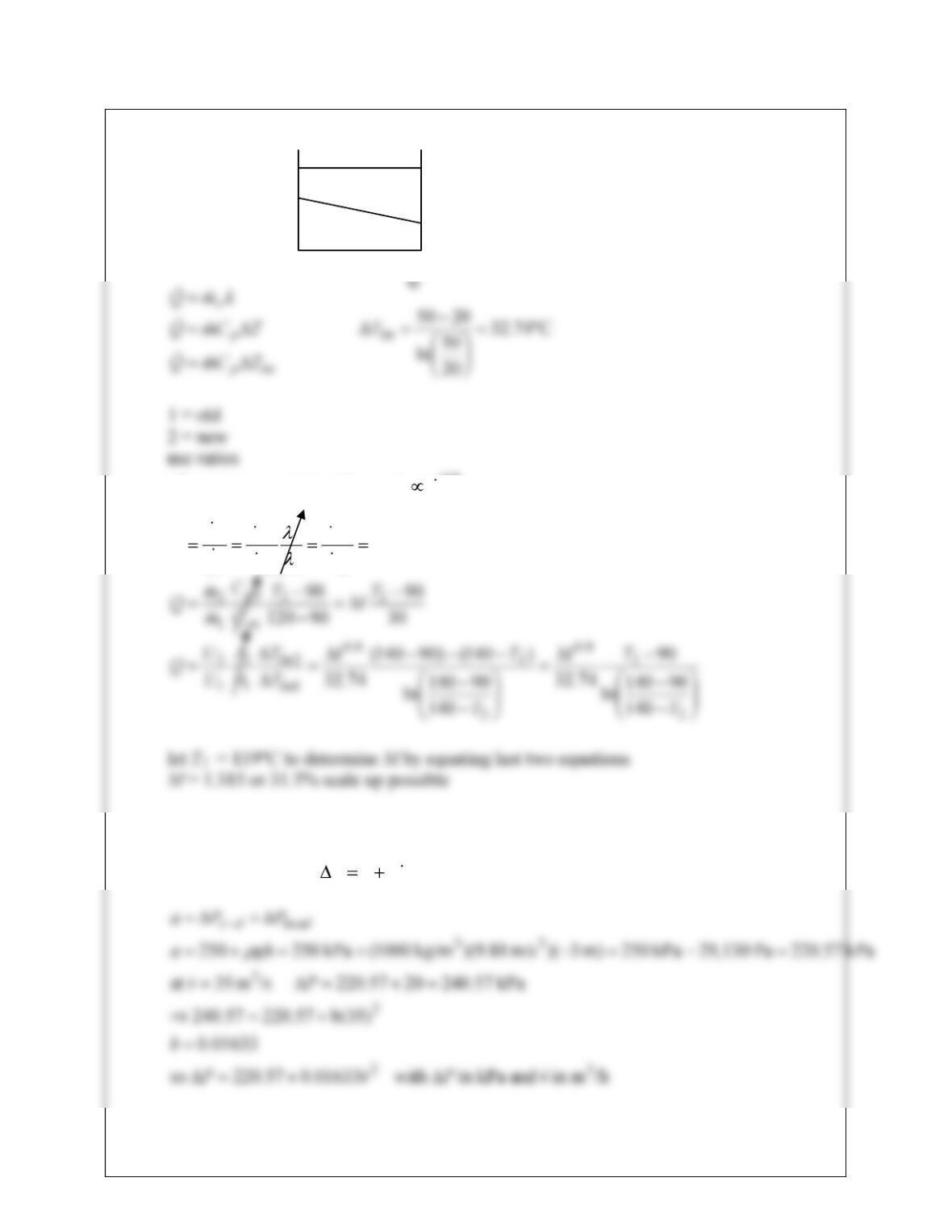
b.
to get system curve 2
vbaP
120
T
140
90
24-27
see plot
1.315(35) = 46 m3/h
maximum flowrate is about 47 m3/h
so it is borderline, but possible
350
400