17-1
Chapter 17
17.1 Transient response of a variable can be obtained from a dynamic simulation, not from a steady state
simulation.
17.2 The flow through a flow device can be related through the pressure drop across it. This creates a well
17.3 Because of the horizontal orientation, the vessel with the larger diameter will have higher pressure at the
17.4 If the cooling duty is provided by evaporation of the refrigerant, the “evaporating/condensing” (fourth
option in the book) heat transfer option can be chosen. If the change in the temperature of the cooling
17.5 The fast reaction can be modeled in a CSTR while the slow reaction can be modeled in a PFR. This will be
computationally efficient because if a single PFR would be used for both the reactions, a very fine grid
17.6 A PID controller would be appropriate due to the time delay. The temperature signal can be processed
through a noise filter before sending it to the PID controller.
17-2
17.7 a) The detailed rigorous heat exchanger is set up using Aspen Exchanger Design and Rating (EDR) V7.2.
In this design of the floating-head, shell-and-tube heat exchanger, the hot fluid is located in the shell side as
the cold fluid contains acid gases. The designed heat exchanger has one shell of OD 0.219 m and ID 0.205
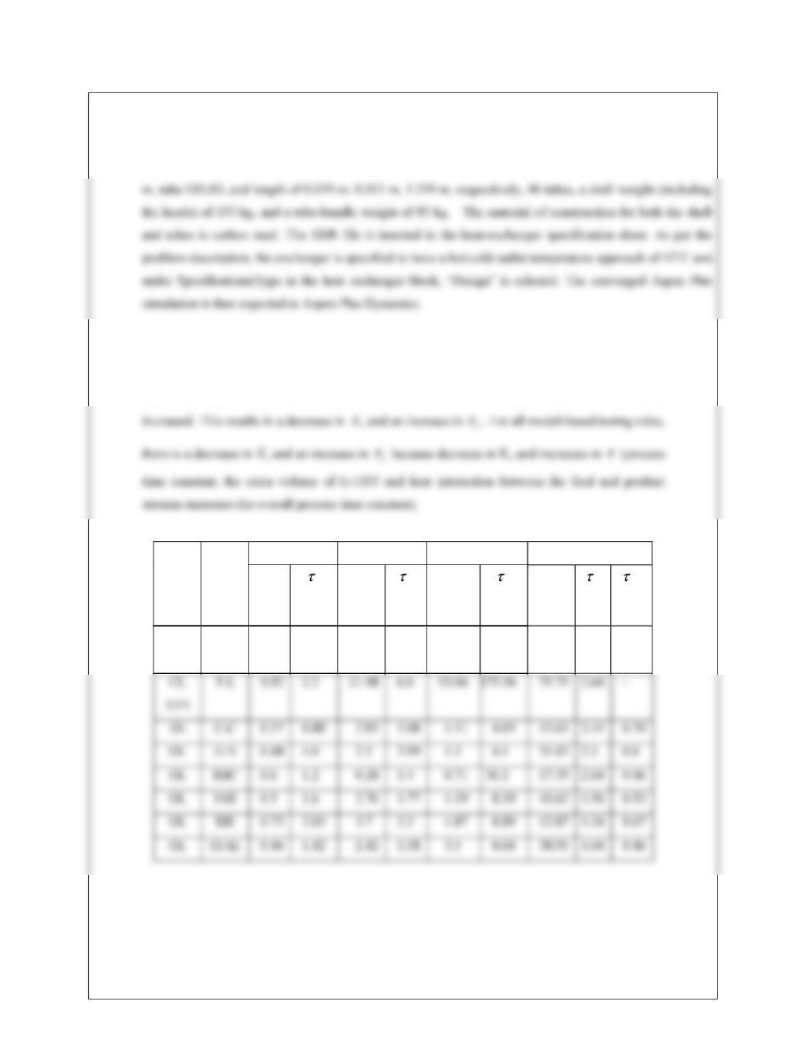
b) This is done similar to Example 17.5. All the tuning parameters are shown below. These tuning
parameters are different than Example 17.5. The stability margin controller tuning parameters
depend on Kcu and Pu. Because of the interaction due to E-1103, Kcu has decreased and Pu has
Method Tuning
Rule
FC-1101 PC-1101 LC-1101 TC-1101
Kc
(%/%)
I
(min)
Kc
(%/%)
I
(min)
Kc
(%/%)
I
(min)
Kc
(%/%)
I
(min)
D
(min)
CL
ATV
Z-N 1.36 0.83 31.97 2.5 77.17 66.5 142.48 0.6 0.15
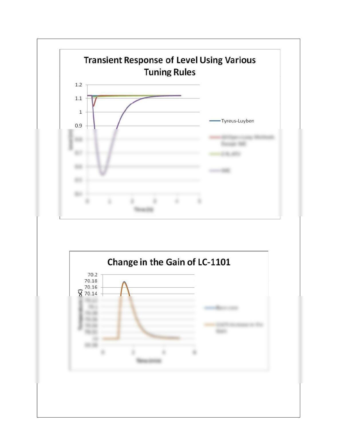
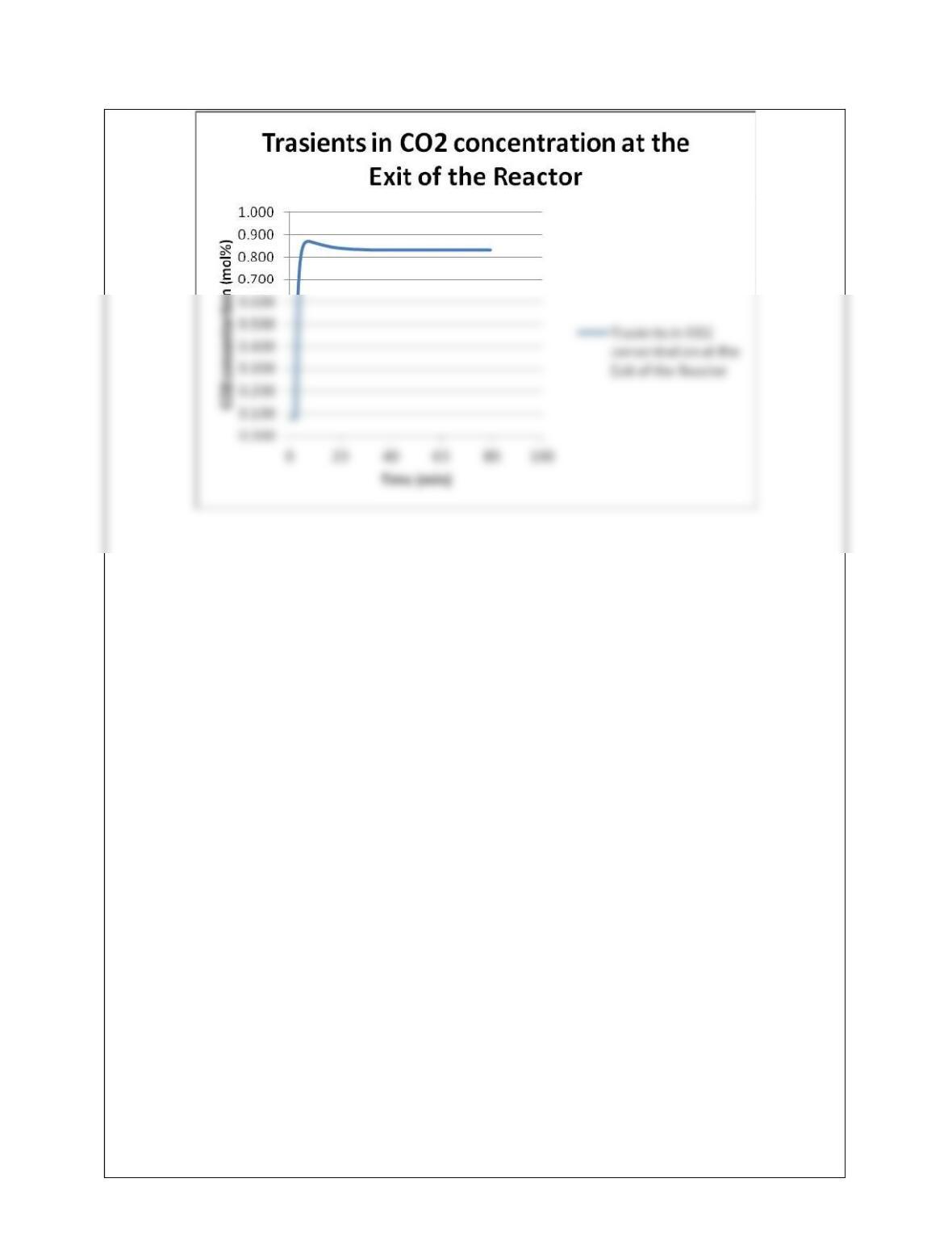
c. The transients are shown below:
17-3
d) The Tyreus-Luyben tuning rule is found to give the best performance (Performance of Z-N, ATV rules is
not much different). As the gain of LC-1101 is changed by 150%, the transient response in TC-1101 is
shown below:
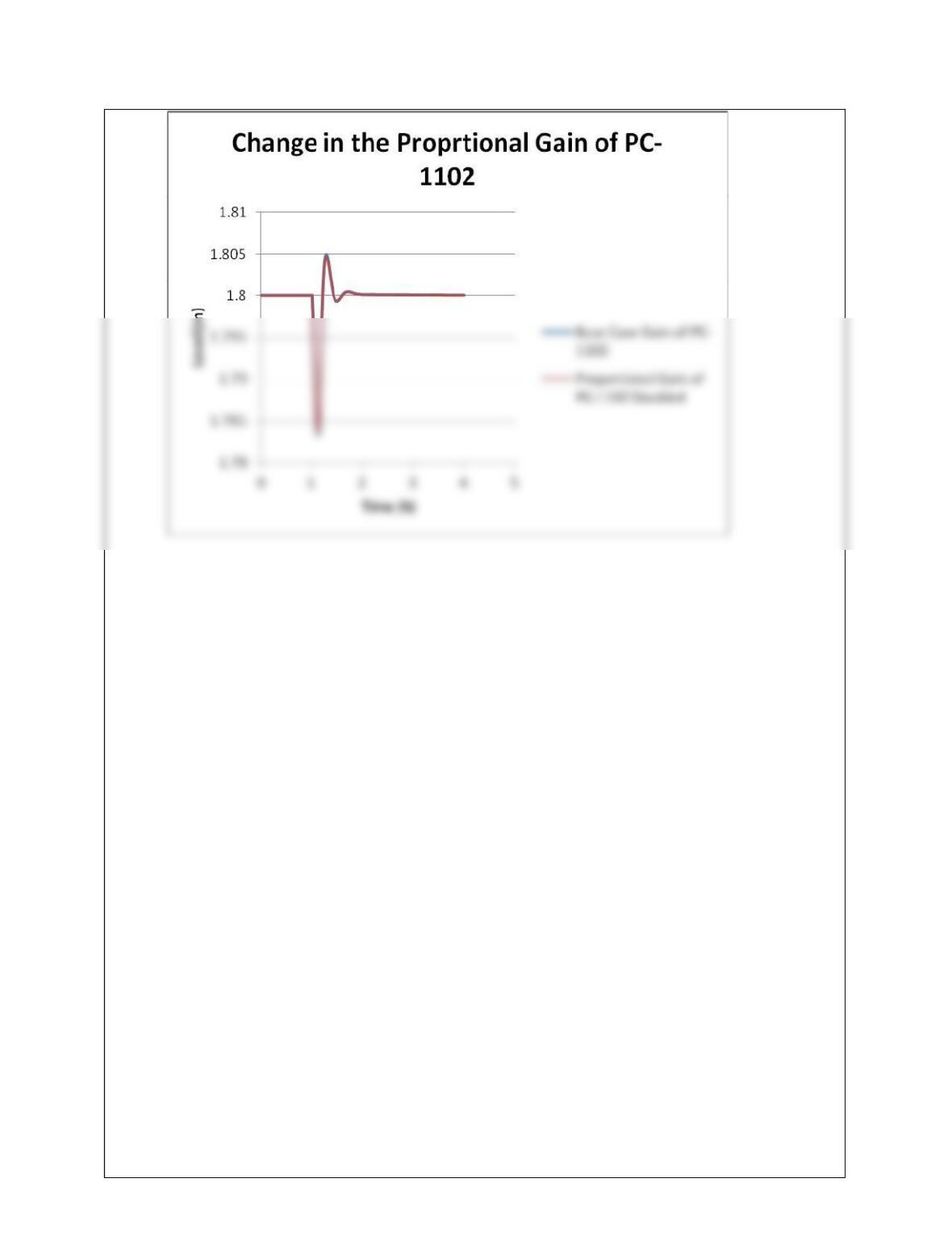
17.8 a) This problem is set up by modifying Example 17.4 as per the problem description.
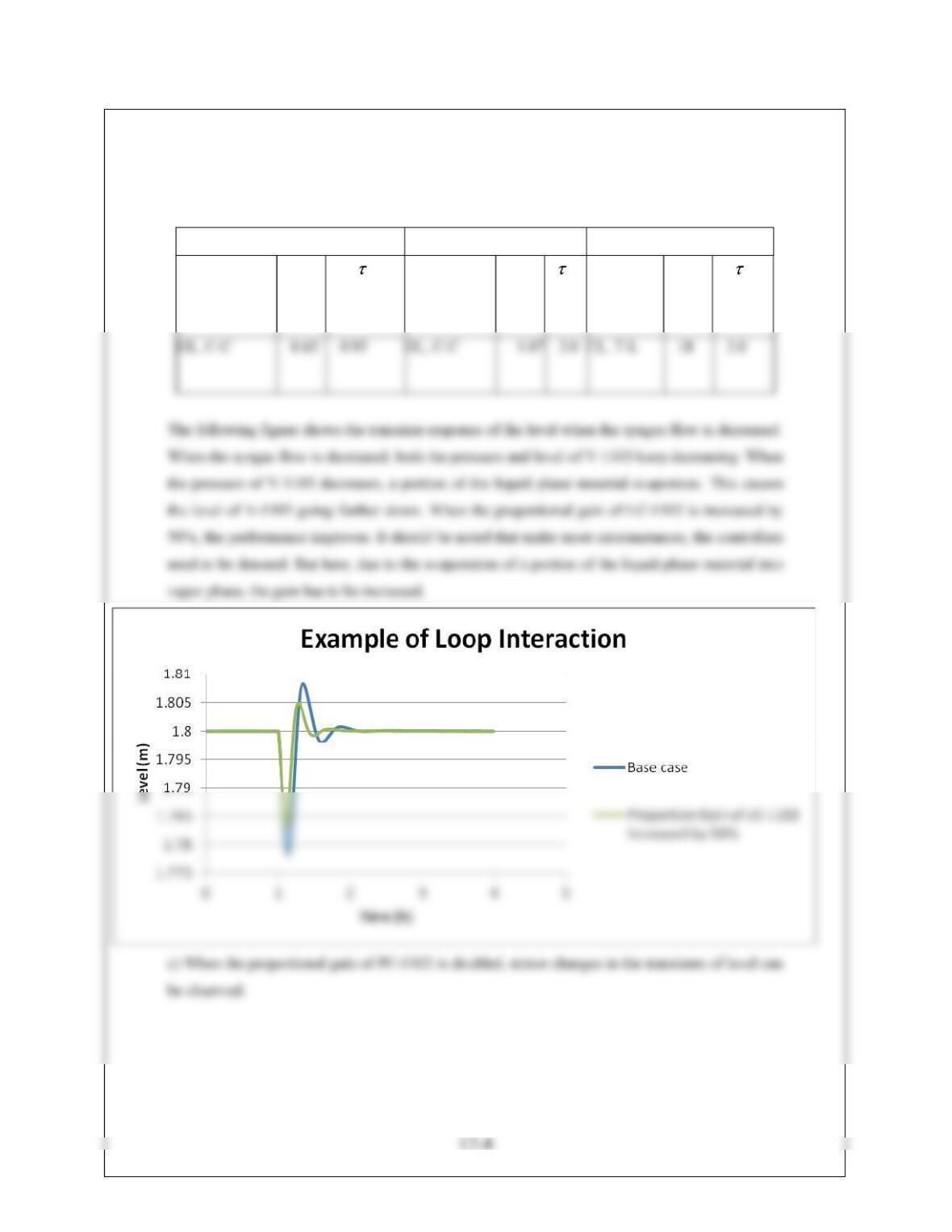
b) The dynamic option for E-1102 is “LMTD”. The length and diameter of V-1103 are calculated
to be 3 m, and 1.2 m, respectively. The tuning parameters with the method and tuning rule are
shown in the following table:
FC-1102 PC-1102 LC-1102
Method&
Tuning Rule
Kc
(%/%)
I
(min)
Method &
Tuning Rule
Kc
(%/%)
I
(min)
Method &
Tuning
Rule
Kc
(%/%)
I
(min)
17-5
17.9 a) The problem is set up in Aspen Plus V7.2. R-1102 is modeled with a “Rstoic” block. Two design
specifications are considered. E-1104. E-1105, and E-1106 are set up as “rigorous” heat exchangers using
the calculation type “shortcut”. As before, an Exchanger Rating and Design file can be inserted. But this
Name|Block Options|Properties.
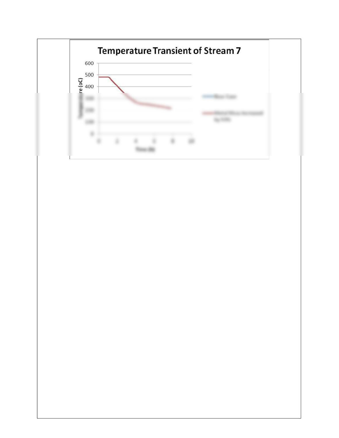
b) Aspen Plus Exchanger Rating and Design is used to model E-1104, and E-1105, E-1106 assuming
shell and tube heat exchanger so that the volume and metal mass of the exchangers can be estimated
separately in an Excel file and then inserted under Block Name|Dynamic. Please note that consideration of
a shell and tube exchanger is not appropriate for this service and other suitable software are suggested that
is capable of modeling the boiler. The heat exchanger area (A_Exch in Aspen Plus Dynamics) are 11.08
FC-1103 XC-1101 FC-1104 FC-1107
Method&
Tuning
Rule
Kc
(%/%)
I
(min)
Method
&
Tuning
Rule
Kc
(%/%)
I
(min)
Method &
Tuning
Rule
Kc
(%/%)
I
(min)
Method
&
Tuning
Rule
Kc
(%/%)
I
(min)
FC-1106 LC-1103 FC-1105 PC-1103
Method&
Tuning
Rule
Kc
(%/%)
I
(min)
Method
&
Tuning
Rule
Kc
(%/%)
I
(min)
Method &
Tuning
Rule
Kc
(%/%)
I
(min)
Method
&
Tuning
Rule
Kc
(%/%)
I
(min)
17-7
Transient
c) In Aspen Plus Dynamics, when the explicit Euler’s method is used, the dynamic simulation could only
be solved with a minimum step size of 0.2×10⁻⁵ sec. Performance of the 4th-order explicit Runge-Kutta
method is similar, and therefore unacceptable. The implicit.Euler method and Gear’s method yield similar
results.
Transient
17-8
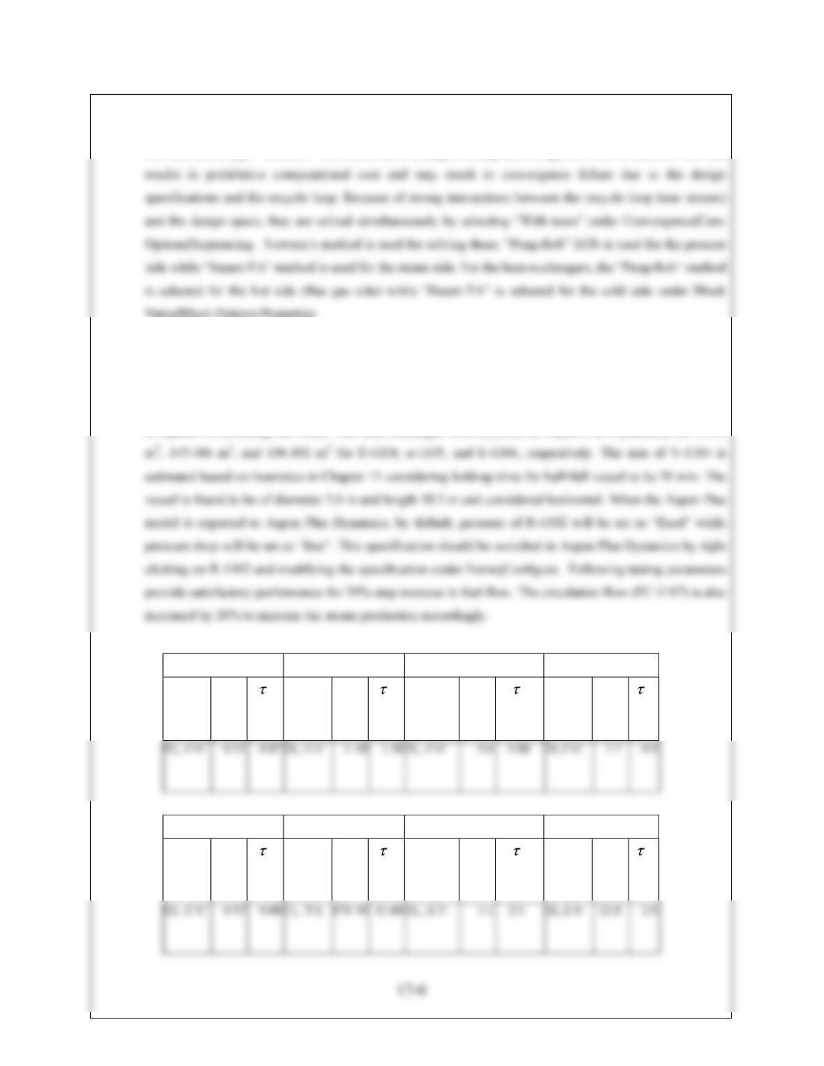
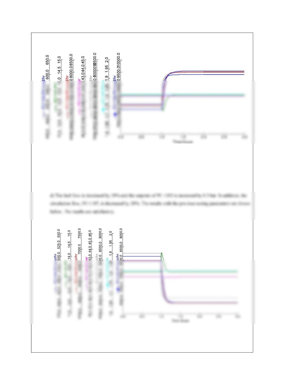
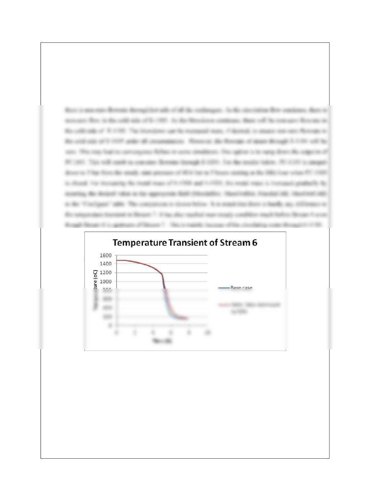
17.10 Gear’s method is used for this study. For this study, first both fuel flow and circulation flow (FC-1107) are
ramped down to 20% in 4 hours. For ramping down the setpoint, right click on the controller icon, then
click on Forms|All Variables and then scroll down to “SPRemote”, select it, right click, select “Ramp” and
enter the final value and duration. FC-1104 is set to auto so that the air flowrate does not change any more.
FC-1103 is completely closed. FC-1107 continues at the same circulation rate. As the flow of air continues,
17-9
17-10
17.11 a) This problem is set up in Aspen Plus V7.2 as per the problem description. A “FSplit” block with split
fraction zero for Stream 11 is used for the recycle loop for prevention of surge. An “isentropic” compressor
V-1105 and V-1106 are vertical. Following the heuristics in Chapter 11, the diameter and length of V-1105
are 0.43 m and 1.1 m, respectively. The diameter and length of V-1106 are 0.3 m and 0.88 m, respectively.
E-1107 is exported with “LMTD” option considering the cooling water temperature to be 30oC. As there is
no flow through CV-1114, it cannot be appropriately sized by Aspen Plus while exporting to Aspen Plus
Dynamics. By trial and error, it can be sized so that its steady state opening remains 30-60% in case of feed
FC-1108 PC-1104 LC-1104 LC-1105 PC-1105
Method&
Tuning
Rule
Kc
(%/%)
I
(min)
Method
&
Tuning
Rule
Kc
(%/%)
I
(min)
Method &
Tuning
Rule
Kc
(%/%)
I
(min)
Method
&
Tuning
Rule
Kc
(%/%)
I
(min)
Method
&
Tuning
Rule
Kc
(%/%)
I
(min)
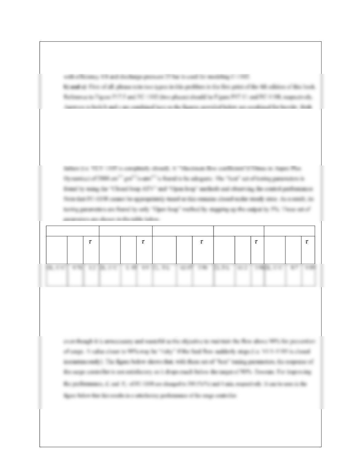
For testing the control performance, the set point of the FC-1108 is specified to be 95% of the steady state
flowrate of Stream 5 so that the flowate of Stream does not go below 90% during the transient. Note that
the value of 95% is arbitrary and any value between 90-100% can be specified as the set point for FC-1108.
A set point closer to 100% will result in opening of the recycle valve as the flow decreases below 100%
17-11
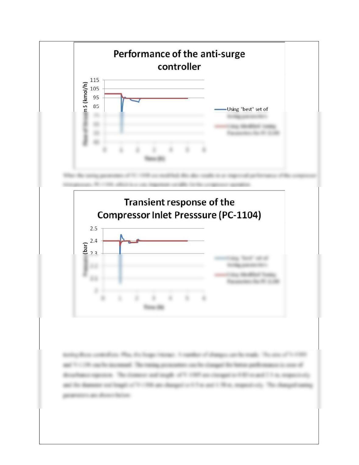
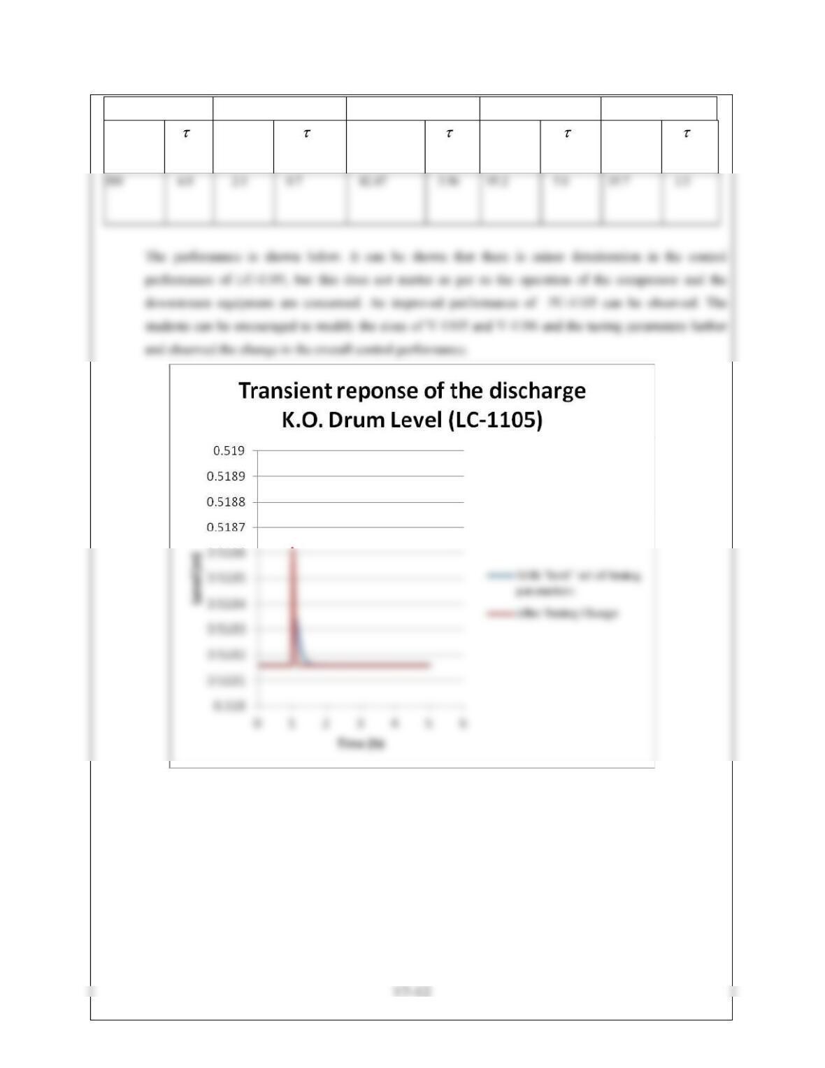
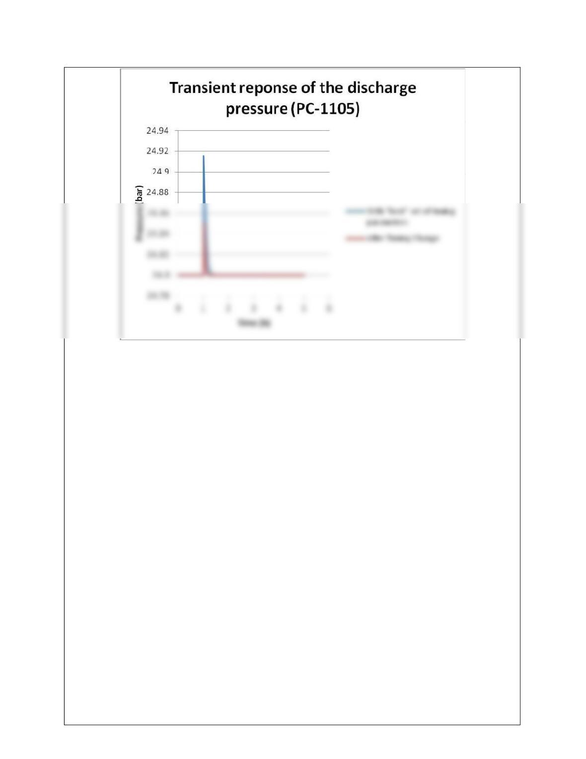
d) and e) Here again the answers are combined for brevity. The figure below shows that the transient
performance of LC-1105 and PC-1105 are not satisfactory when the pressure of Stream 1 is changed from 3
bar to 3.2 bar. The main reason for poor performance is that this disturbance has not been considered while
FC-1108 PC-1104 LC-1104 LC-1105 PC-1105
Kc
(%/%)
I
(min)
Kc
(%/%)
I
(min)
Kc
(%/%)
I
(min)
Kc
(%/%)
I
(min)
Kc
(%/%)
I
(min)
17-13
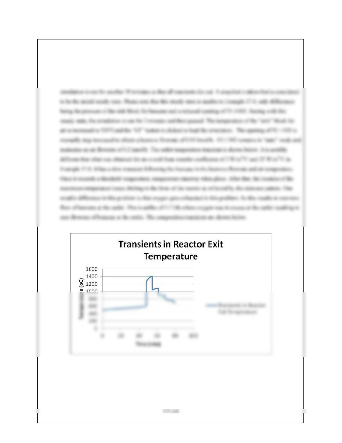
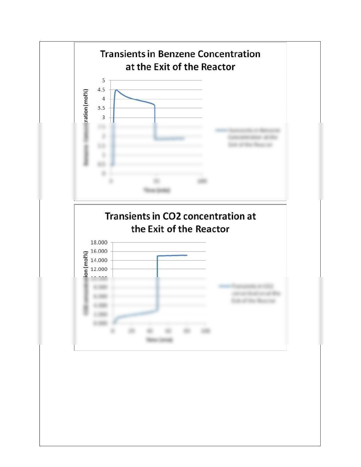
17.12 This problem is set up in Dynsim 4.5.3 by modifying Example 17.6. In order to increase the flowrate of
benzene to 0.01 kmol/h, the pressure of the “sink” block for benzene is increased to 4.5 kg/cm2. The “LF”
button is clicked to load the simulation. The simulation freezes at this point. It is restarted and run till FC-
1103 adjusts the MV to bring back the benzene flowrate to its steady state value of 0.001 kmol/h. The
17-15
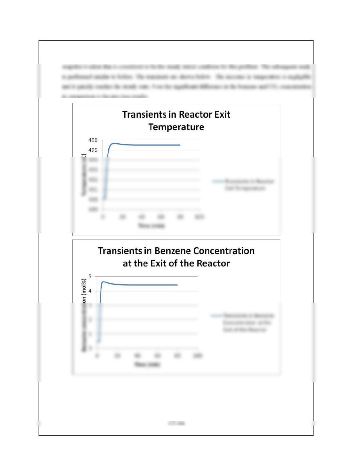
17.13.The previous problem is modified by changing the overall heat transfer coefficient. The “LF” button is
clicked to load the simulation. The simulation is run for about 10 minutes so that it reaches steady state. A
17-17