16-1
Chapter 16
16.1 Process simulators generate an incidence matrix based on the process flowsheet and then
perform row operations to determine partitioning and precedence ordering.
16.2 In Stream 1, the number of variables for which a good guess is not available is 8 whereas
in Stream 2, the number of variables for which a good guess is not available is 7
16.3 In this case, there are 8 tear variables. Using Newton’s method, it will require N+1=9
flowsheet passes in comparison to 1 flowsheet pass for Broyden’s method.
16.5 In an optimization study with a flowsheet, the feasible region is defined by the process
16.6 The constraints are due to the model for calculating activity coefficients for the species in
16-2
16.7 Problem 13.29 is considered and a design specification is set up under Design Specs in
the stripper block, where the specification is to maintain the mole purity of H2S at
16.8 Problem 16.7 is modified as per the problem description. E-2001 is set up with a 10 C
temperature approach. The “Split fraction” of Stream 9 is specified as 0.005 as per the
problem description. Two mixers, MX-2001A and MX-2001B, are considered. In the
first mixer, MX-2001A, Stream 11, i.e. pure MDEA at 1.5 atm pressure and 25 C
temperature, is mixed. A calculator block, C1, is created as follows;
16-3
As per the heuristics in Chapter 11, the efficiency of P-2001 is specified to be
45%.
a. For aiding in convergence, following things should be done:
–Stream 2 should not be connected first. Note that the water content in Stream
the solvent should be changed to 2.4 atm now. At this point, the stream
properties of the solvent to T-2001 and the solvent at the outlet of E-2002
should be similar. Delete the stream at the outlet of E-2002 and right click on
the solvent stream (to T-2001) and click on “Reconnect source” and connect it
to the outlet of E-2002. This will force Aspen Plus to consider this stream to
16-4
b. The results of Streams 3 and 6 are shown below.
Stream 3 Stream 6
Temperature ( C) 39.93 94.33
Total flow (kmol/h) 45.734 2.011
Composition (mole fraction)
CO 0.20 1.47e-4
H2 0.13 9.0e-5
16.9
a. It can be seen that, at least two streams need to be torn for opening each loop once. So,
the first criterion for tear stream(s) selection that seeks to minimize the number of tear
streams is satisfied by choosing two tear streams. The second criterion seeks to
minimize the total number of tear stream variables. It has been suggested in Chapter 16
b. Aspen Plus selects Stream 7 and Stream 2 as the tear streams, which is in agreement
with our choice.
c. Students can select other tear streams and note the differences in computational time.
16-6
16.10 Before implementing the design block, a few changes need to be made in the previous
simulation. First, SP-2001 has been specified before with a given split fraction.
However, as suggested in Example 16.6, the flowrate of Stream 10 can be declared as
the manipulated variable in the design block. However, when this change in
The total mole fraction of MDEA in Stream 10 can be calculated by adding
mole fractions of MDEA and MDEAH+in Stream 10. As suggested earlier, the
total mole fraction of MDEA in Stream 10 also can be calculated by sending
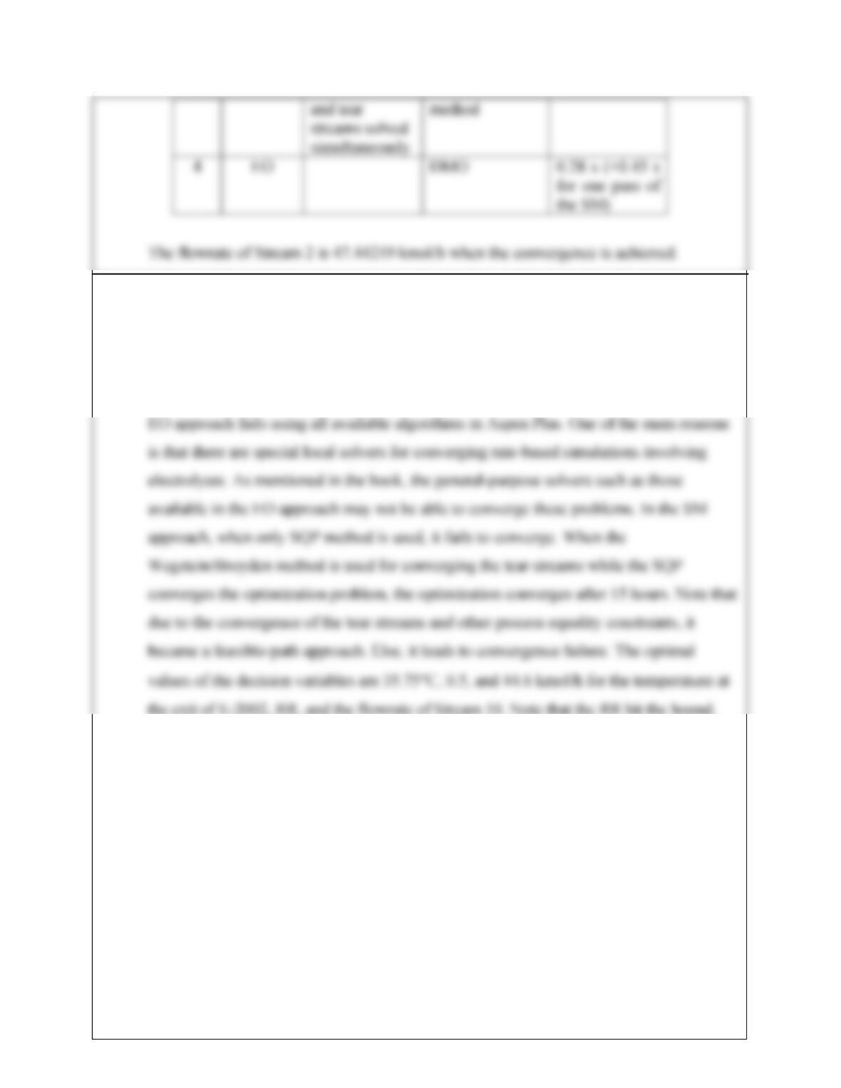
Case Solution
approach
Sequence Algorithm Time taken
1
SM
Design block
nested inside
Tear streams-
Wegstein’s
method, Design
block-
3 min
16-7
16.11 For this optimization problem, the design spec that manipulated the solvent circulation
flow to satisfy the H2S concentration in Stream 3 should be removed. The H2S
concentration should be posed as a constraint. The bounds on the circulation rate are 40-
60 kmol/h and on the reflux ratio (mole basis) is 0.5-1. This problem is hard to solve. The
16-8
16.12
a. This problem is set up in Aspen Plus V7.2 as per the problem description considering
ethylene and pure O2 as the reactants being available at 25 bar and 230oC. As the
concentration basis is partial pressure, the compatible unit for the pre-exponential factor,
A, is (depending upon the rate expression) kmol/(kg cat s Pa). By performing the required
b. Calculation of the heat transfer coefficient using the Gnielinski correlation is performed
using FORTRAN in the calculator block. However, before performing the calculation,
viscosity, heat capacity, and thermal conductivity of the feed streams needs to be
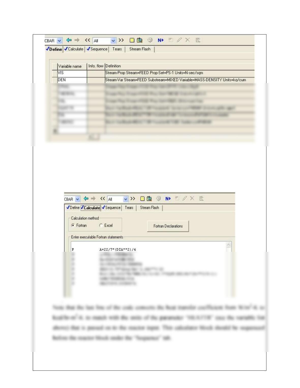
16-9
Note that the tube diameter and number of tubes are also declared under the variables so
that the heat transfer coefficient is updated in part c of this problem when these
parameters are changed.
Under the “Calculate” tab, following FORTRAN statements are written:
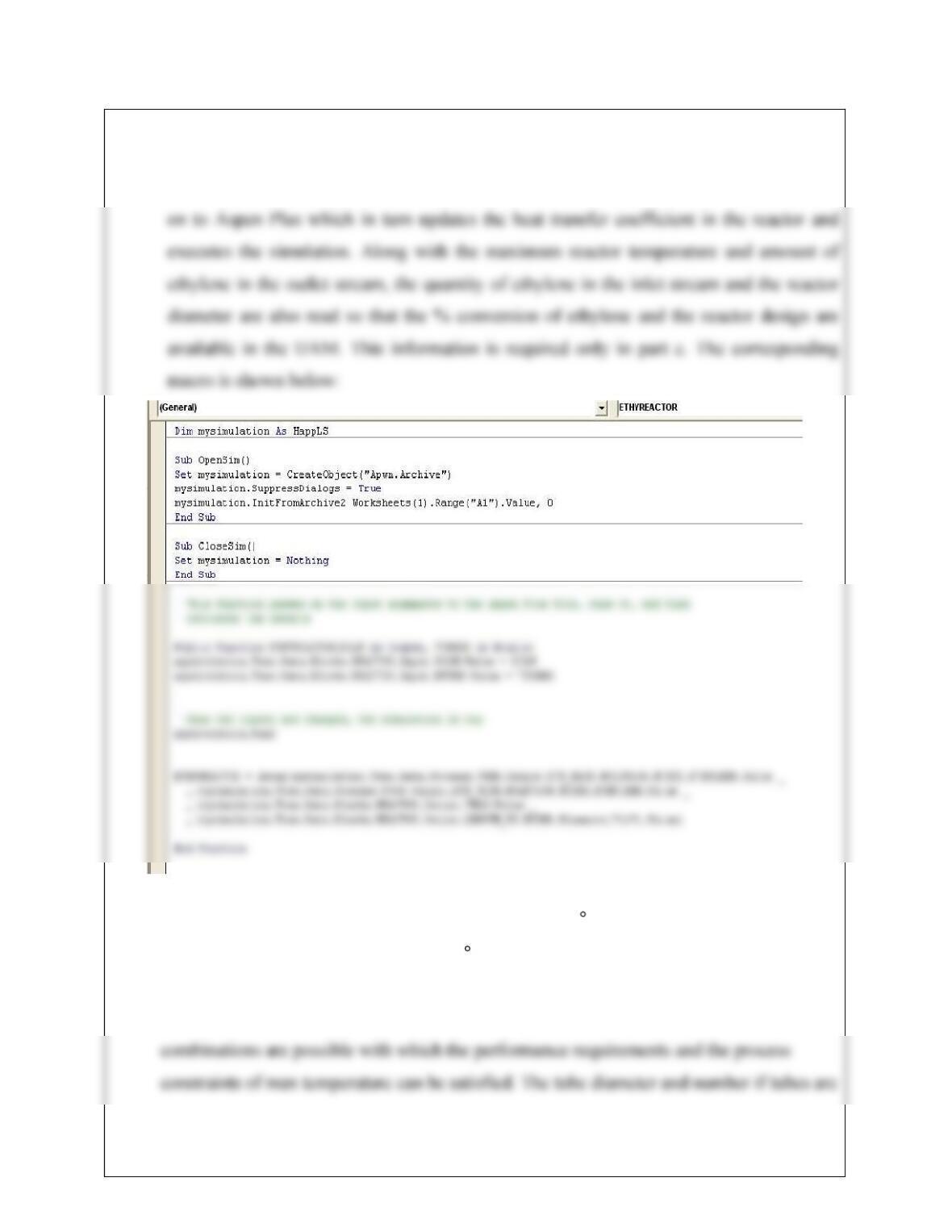
16-10
Another UAM is created in Excel, similar to Example 16.2, where the maximum reactor
temperature and unreacted ethylene in the outlet stream is read. In view of part c of this
problem, the UAM is created so that, the number of tubes and the tube diameter is passed
Please see Example 16.2 to see more details about UAM in Excel for interfacing with
Aspen Plus. The maximum reactor temperature is 1138.2 C which is much higher than the
desired maximum temperature below 270 C. Also note that the ethylene has completely
converted.
c. Here the number of tubes, tube diameter, and length should be varied. A number of
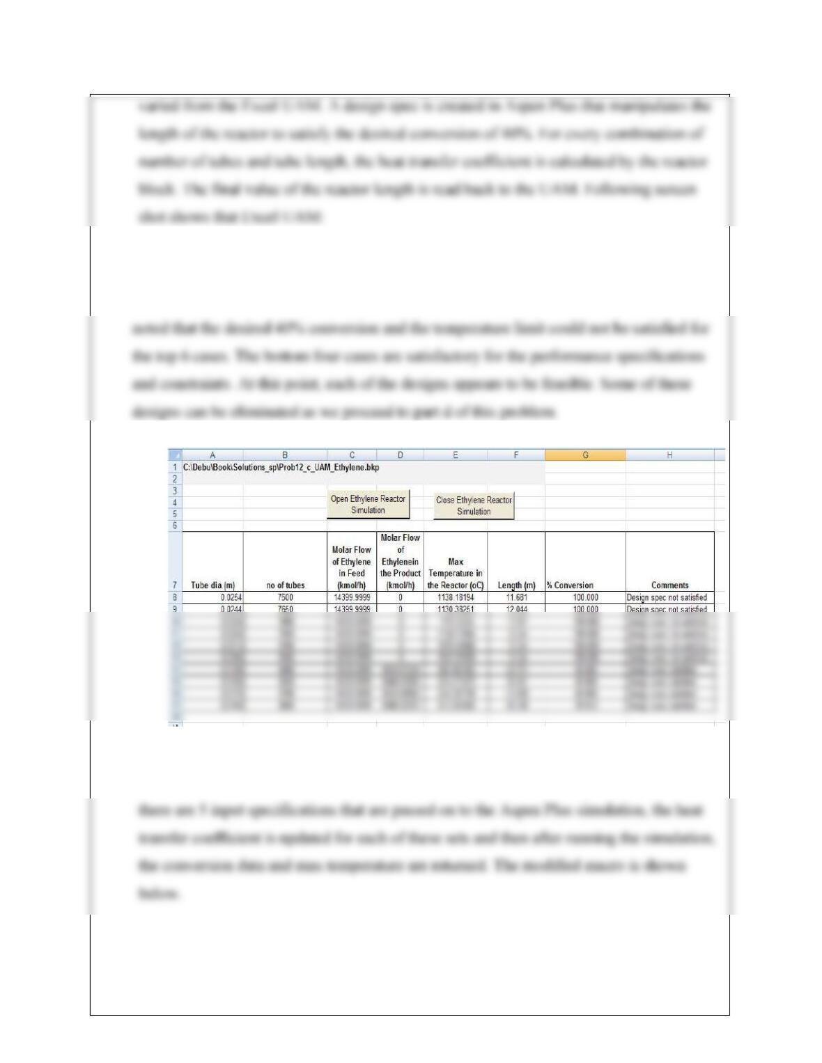
16-11
Here the top row shows the results due to the reactor design in part b. The tube diameter is
decreased by 0.001 whereas the number of tubes is changed by 150 at every step. It can be
d. Here the ethylene and oxygen flowrates are varied by +/-30% and with the last four design
cases, the max temperature is observed. Considering the three design parameters, now