13-97
CHEMCAD 5.6.0 Page 10
Job Name: formalin_JAS_2008 Date: 12/14/2008 Time: 14:45:38
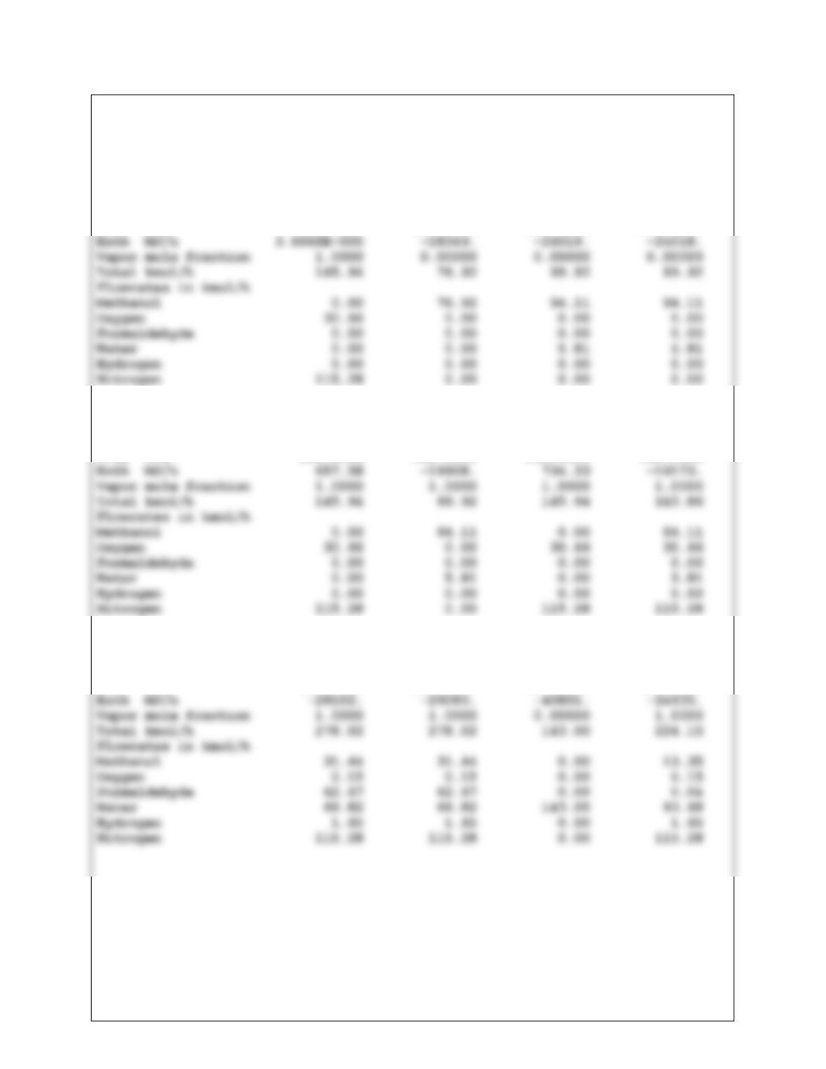
FLOW SUMMARIES
Stream No. 1 2 3 4
Stream Name
Temp C 25.0000 30.0000 40.6637 40.7822
Pres kPa 101.3250 120.0000 101.3250 300.0000
Stream No. 5 6 7 8
Stream Name
Temp C 183.0128 150.0000 200.0000 171.9390
Pres kPa 300.0000 265.0000 265.0000 255.0000
Stream No. 9 10 11 12
Stream Name
Temp C 200.0000 100.0000 30.0000 84.5653
Pres kPa 185.0000 150.0000 150.0000 140.0000
13-98
CHEMCAD 5.6.0 Page 11
Job Name: formalin_JAS_2008 Date: 12/14/2008 Time: 14:45:38
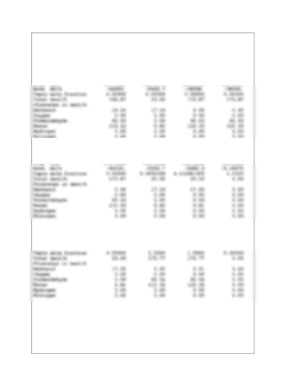
FLOW SUMMARIES
Stream No. 13 14 15 16
Stream Name
Temp C 89.8453 75.4568 106.6348 106.7102
Pres kPa 150.0000 130.0000 150.0000 350.0000
Stream No. 17 18 21 22
Stream Name
Temp C 35.0000 73.3569 75.5718 75.5718
Stream No. 23 24 25 26
Stream Name
Temp C 75.5718 106.6357 106.6357 106.6357
Pres kPa 130.0000 150.0000 150.0000 150.0000
Enth MJ/h –5682.7 –33615. –33615. 0.00000
13-99
CHEMCAD 5.6.0 Page 12
Job Name: formalin_JAS_2008 Date: 12/14/2008 Time: 14:45:38
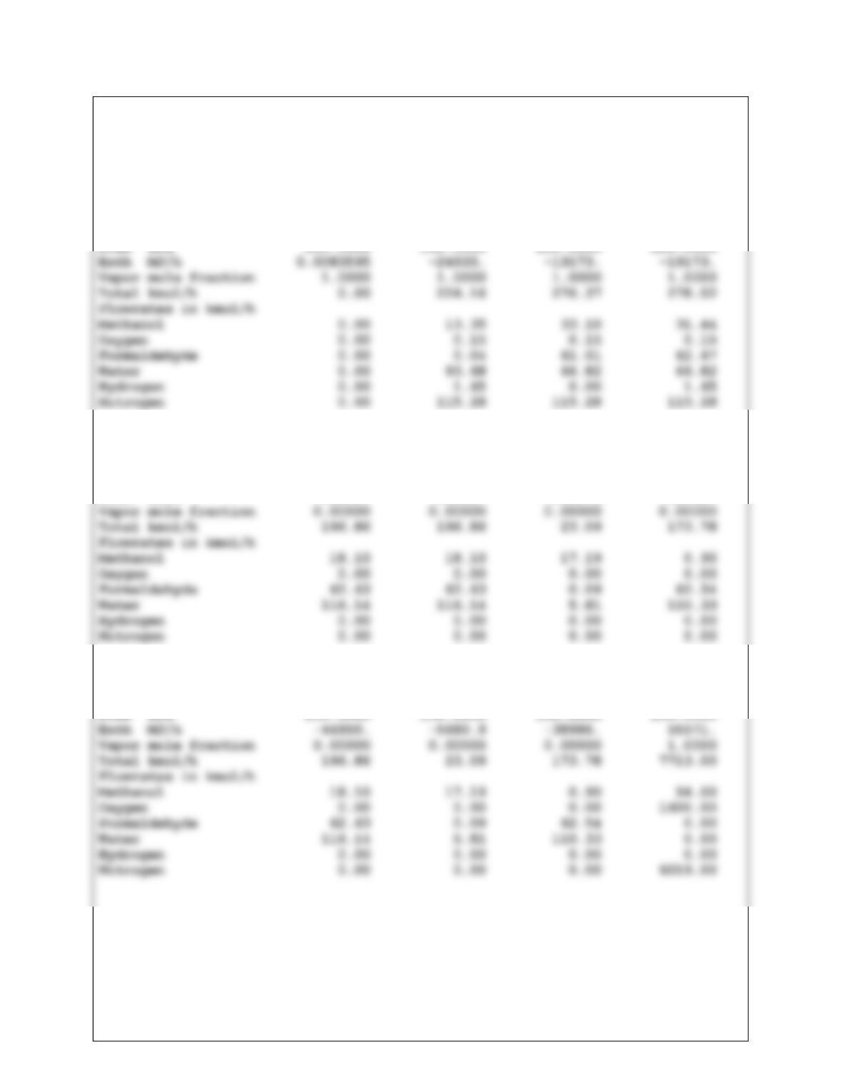
FLOW SUMMARIES
Stream No. 64 65 68 69
Stream Name
Temp C 89.8453 84.5669 934.7972 923.0992
Pres kPa 150.0000 140.0000 255.0000 220.0000
Stream No. 70 72 73 74
Stream Name
Temp C 89.8453 89.8453 75.5764 106.6356
Pres kPa 150.0000 150.0000 130.0000 150.0000
Enth MJ/h –44950. –44950. –5681.2 -38985.
Stream No. 76 77 78 98
Stream Name
Temp C 89.8453 75.5772 106.6358 350.0000
Pres kPa 150.0000 130.0000 150.0000 250.0000
CHEMCAD 5.6.0 Page 13
Job Name: formalin_JAS_2008 Date: 12/14/2008 Time: 14:45:38
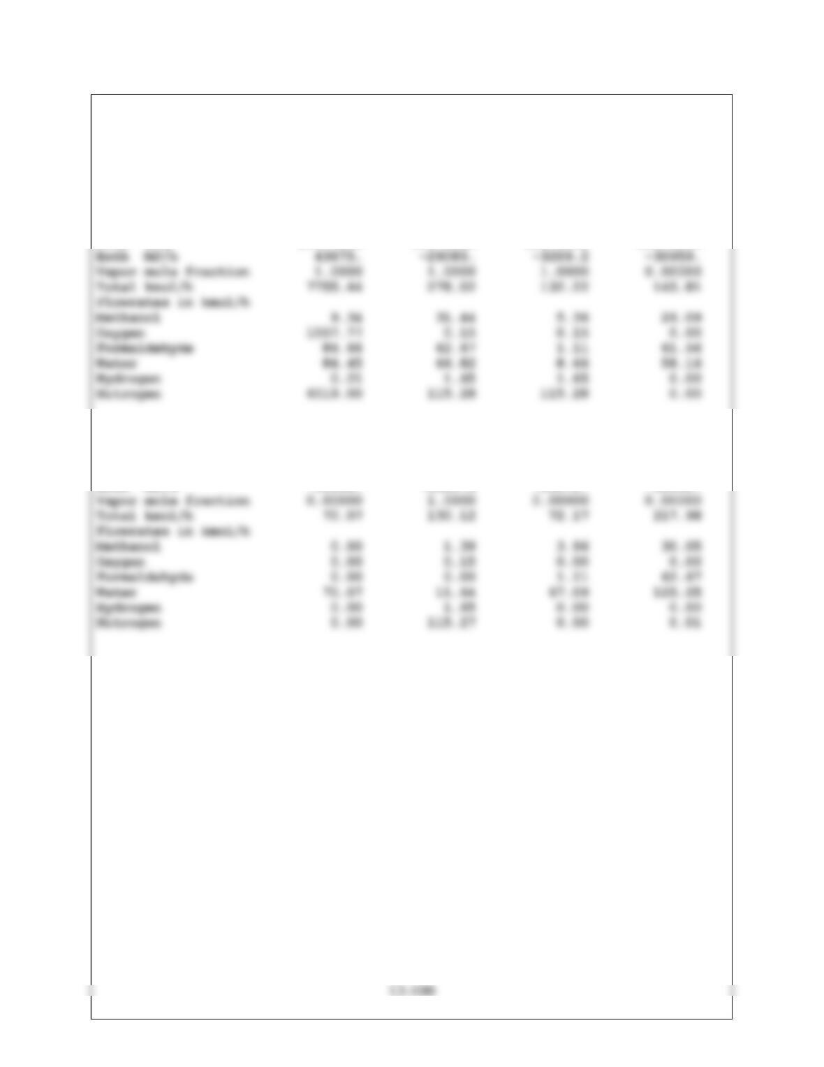
FLOW SUMMARIES
Stream No. 99 100 101 102
Stream Name
Temp C 354.2749 100.0000 50.0000 50.0000
Pres kPa 250.0000 150.0000 115.0000 115.0000
Stream No. 103 104 105 106
Stream Name
Temp C 30.0000 42.5463 42.3507 47.7261
Pres kPa 150.0000 105.0000 115.0000 115.0000
Enth MJ/h –19992. –3029.3 –20172. -51131.
13-101
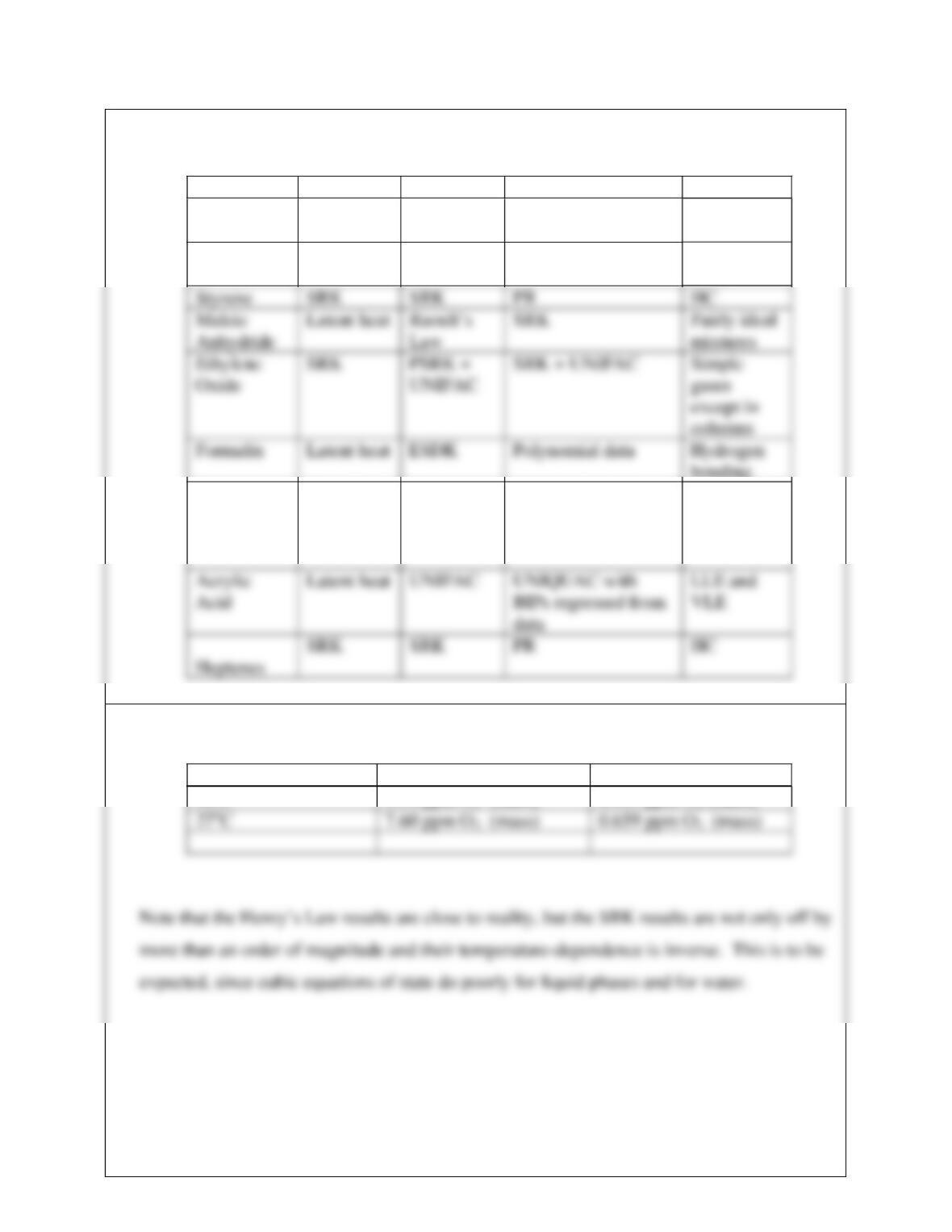
13.24 The Thermodynamic models used are:
Process Enthalpy Phase Equ. Alternate Notes
DME Latent heat UNIFAC UNIQUAC/UNIFAC 2 liquid
phases
EB Latent heat UNIFAC UNIQUAC/UNIFAC Lack of
BIPs
bonding
Acetone Latent heat UNIFAC UNIQUAC with
BIPs regressed from
data
Azeotrope
13.25 The following results are from Chemcad for vapor-liquid equilibrium of water and air:
T Henrys Law SRK
10oC 11.4 ppm O2 (mass) 0.413 ppm O2 (mass)
15-102
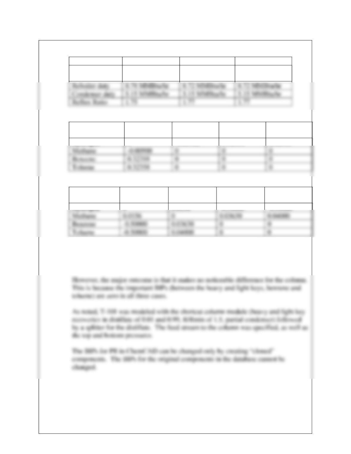
13.26 The following is from the Chemcad simulation of T-101:
SRK PR PR Bips = zero
Number of
stages
23.3 23.5 23.5
Chapter 14 SRK
BIPs
Hydrogen Methane Benzene Toluene
Hydrogen 0 -0.00900 0.32358 0.32358
Chapter 15 PR
BIPs
Hydrogen Methane Benzene Toluene
Note that the BIPs are very different for the SKR and PR models, even differences in
sign! Note also that there are more binaries represented in the PR database on
ChemCAD for this system than for SRK.
15-103
13.27 The simulation is set up in Aspen Plus V7.2. It can be set up in other compatible software
platforms as well. The steps required are similar to Example 13.8 and therefore, will be
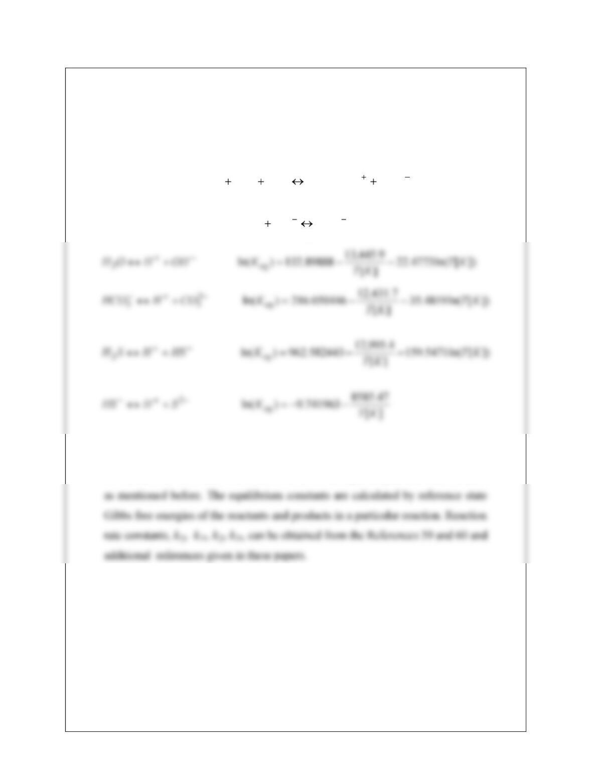
described in brief here. The following equilibrium reactions are generated and the
equilibrium constants are estimated by Aspen Plus and these are in agreement with the
existing literature. The equilibrium constant of Reaction (5) is modified to match the data
in References [59] and [60].
322 ““‘““‘
1
1
HCONHRRROHCONRRR
f
b
k
k
32
2
2
HCOOHCO
f
b
k
k
Here T is in K and the concentration basis is mole fraction and the reference state
for the activity coefficients of ions is chosen to be aqueous phase infinite dilution
15-104
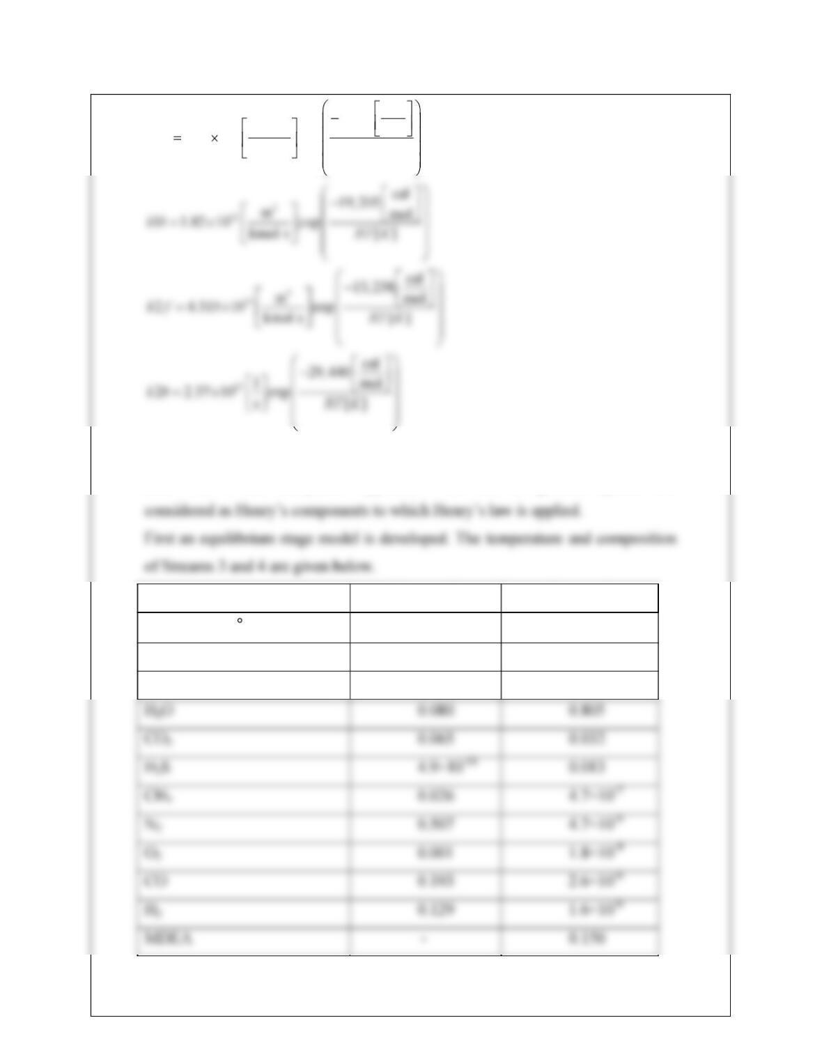
3
7
cal
9,093
mmol
1 2.91 10 exp
kmol s [ ]
k f RT K
The electrolyte NRTL (“ElecNRTL” in Aspen Plus) thermodynamic model is
used with a true component approach. Note that all gaseous species are
Stream 3 Stream 4
Temperature ( C) 54.20 41.38
Total flow (kmol/h) 46.243 60.958
Composition (mole fraction)
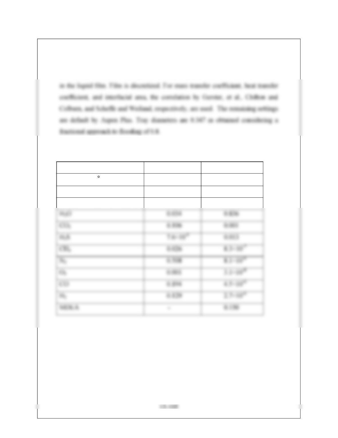
13.28
For non-equilibrium stage modeling, the simulation is set up as specified in the
problem description. Diffusion resistance in both the liquid and vapor films is
considered. Because of the rapid ionic reactions, the reactions are also considered
The results of Streams 3 and 4 are shown below:
Stream 3 Stream 4
Temperature ( C) 37.91 37.83
Total flow (kmol/h) 46.053 63.182
Composition (mole fraction)
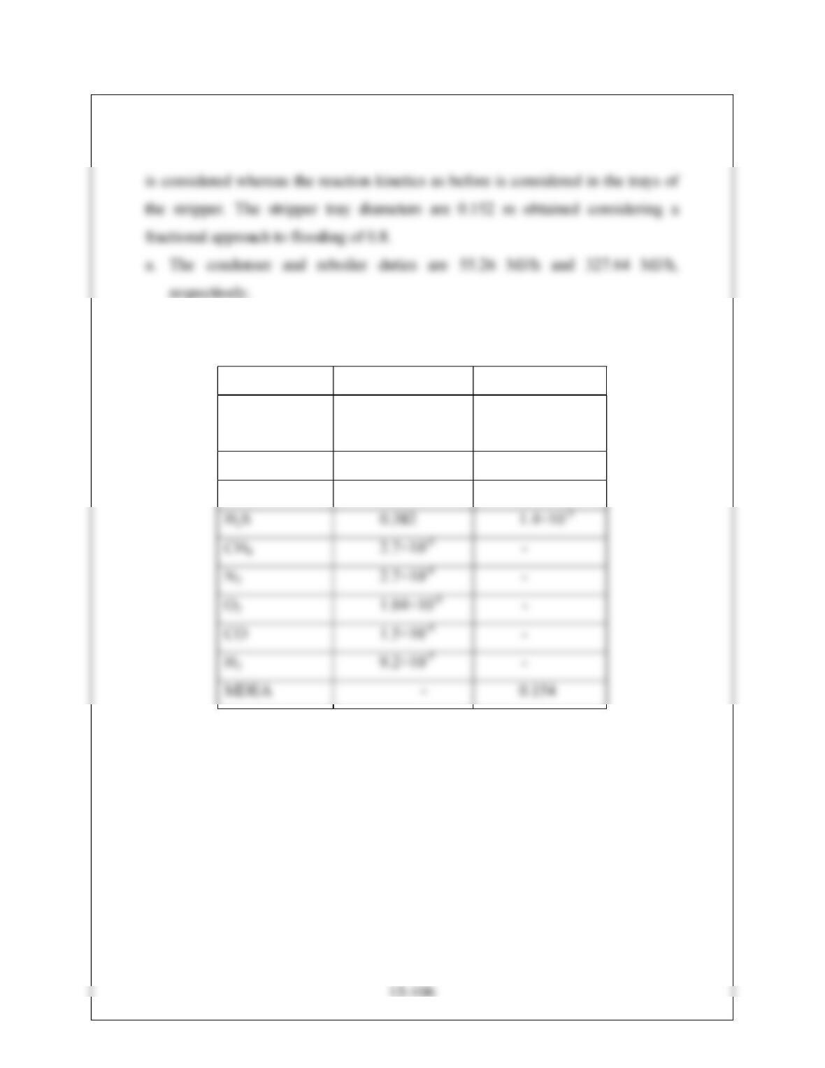
13.29
The problem is set up in continuation of the previous problem. The same reaction
kinetics as before are used. In the condenser and reboiler, equilibrium chemistry
b. The results of Streams 6 and 7 are given below
Stream 6 Stream 7
Composition
(mole fraction)
H2O 0.571 0.844
CO2 0.045 4.28×10⁻⁷
c. For increasing the purity of Steam 7, one can increase the reboiler duty, and/or
increase the reflux ratio, and/or decrease the column pressure.

15-107
13.30 This problem is set up in Aspen Plus V7.2 similar to Project B.15. Similar to Project B.15,
the following reactions are considered with suitable modifications as this is a combustor
and 10% excess air is used. Following reaction is considered in R-1501A similar to
Reaction 15.1 by only adding Cl2 in this reaction,
The following coefficient table is used
C0.55006
CO 0.02190
CO 0.01170
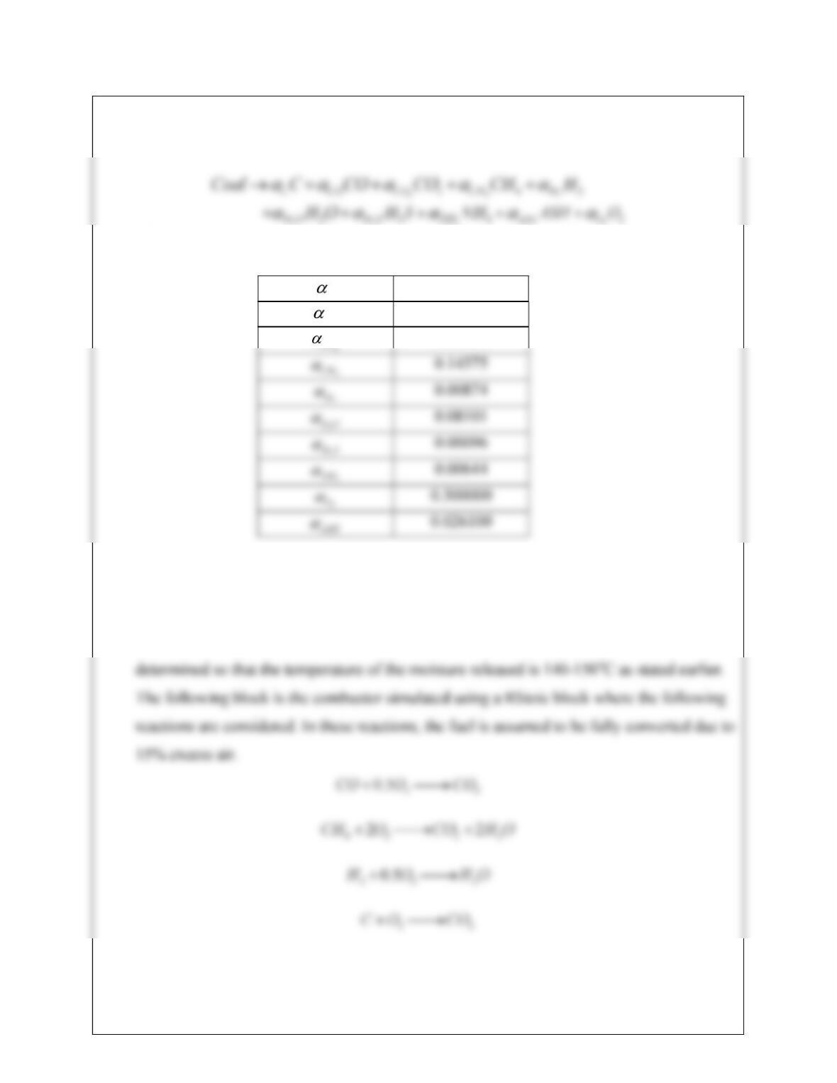
Another block similar to R-1501B is considered for simulating the combustor where the
following reactions are considered. In these reactions, the fuel is assumed to be fully
converted due to 10% excess air.
15-108
Of course the gasifier block (R-1501C) is now removed and water stream is removed. A
calculator block is written for setting the air flowrate at 10% excess than the stoichiometric
requirements (disregarding O2 that gets produced due to coal devolatilization in the RYield
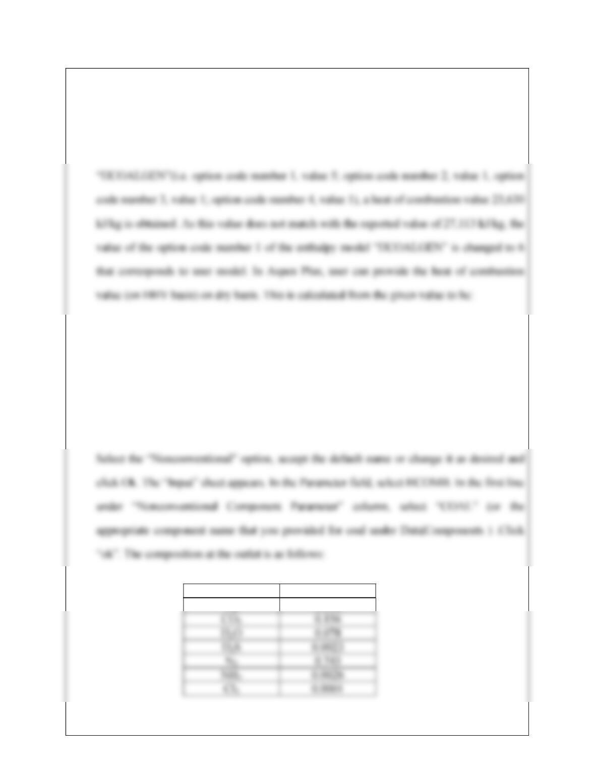
block). Using the same option code as Project B15 for the enthalpy model
heat of combustion (dry basis) = heat of combustion(wet basis)(100)/(100-%moisture)
= (27,113)(100)/(100-11.12) = 30,505 kJ/kg.
This value can be inserted by first selecting Properties|Parameters|Pure Component under
Data browser. Click “New” to open the “New Pure Component Parameters” dialog box.
Species Mole fraction
O2 0.018
15-109
13.31 This problem is set up in Aspen Plus V7.2. The required data are obtained from the
example files provided in Program Files\AspenTech\Aspen Plus V7.2\GUI\App and
another document (Aden A., Ruth M., Ibsen K., Jechura J., Neeves K., Sheehan J.,
be -233 kcal/mol and -469 kcal/mol, respectively. For solids heat capacity calculation,
only first two coefficients are considered to be non-zero in the Aspen Solid Heat Capacity
Polynomial: Cp(cal/mol-K) = a + bT . The values of the coefficient a are 41.0509 and
42.0399 and that of coefficient b are 0.1605 and 0.1191 for cellulose and lignin,
respectively. The solids molar volumes are considered to be 106 cc/mol, 86.4 cc/mol, and
15-110
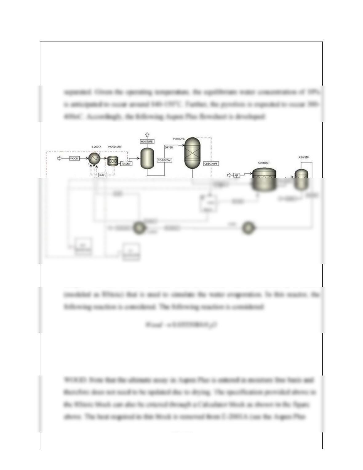
13.32 This problem is set up in Aspen Plus V7.2 similar to Problem 13.30. When the wood is
heated in E-2001, partial devolatization takes place along with separation of water vapor.
As mentioned in the problem, 90% of the moisture in the feed is considered to be
The feed stream is declared as in Problem #13.30 based on the proximate and ultimate
assays. The first block is a heater block (E-2001A). This is followed by a reactor
Fractional conversion of wood is specified to be 0.079201. In addition, the moisture
content in the proximate assay is changed to 0.9556 in the Moisture field in the RStoic
block under: Component Attr.|NC|WOOD|PROXANAL where the component ID is
15-111
flowsheet above). After that, the moisture is flashed off. This is followed by the block
where the following reaction is considered in a RYield block:
23
2 2
The following coefficient table is used:
C0.38271
CO 0.03276
The temperature of the RYield is specified to be 350oC as mentioned before. As part of the
heat required in the RYield block is provided by E-2001, the heat stream from the RYield
block is split. 26% of the heat is accounted for in E-2001A. This split fraction is
A calculator block is written for setting the air flowrate at 15% excess than the
stoichiometric requirements (ignoring O2 produced in the RYield block). The enthalpy
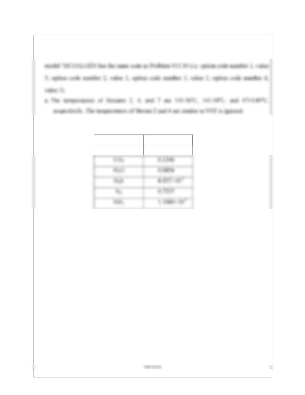
b. The composition of Stream 7 is:
Species Mole fraction
O2 0.0548
c.The HHV according to the enthalpy model can be compared and the reported HHV can be
inserted similar to Problem 13.30