Chapter 1
1.1 Block Flow Diagram (BFD)
Process Flow Diagram (PFD)
1.2 P&ID
1.3 It is important for a process engineer to be able to review a 3-dimensional model prior to
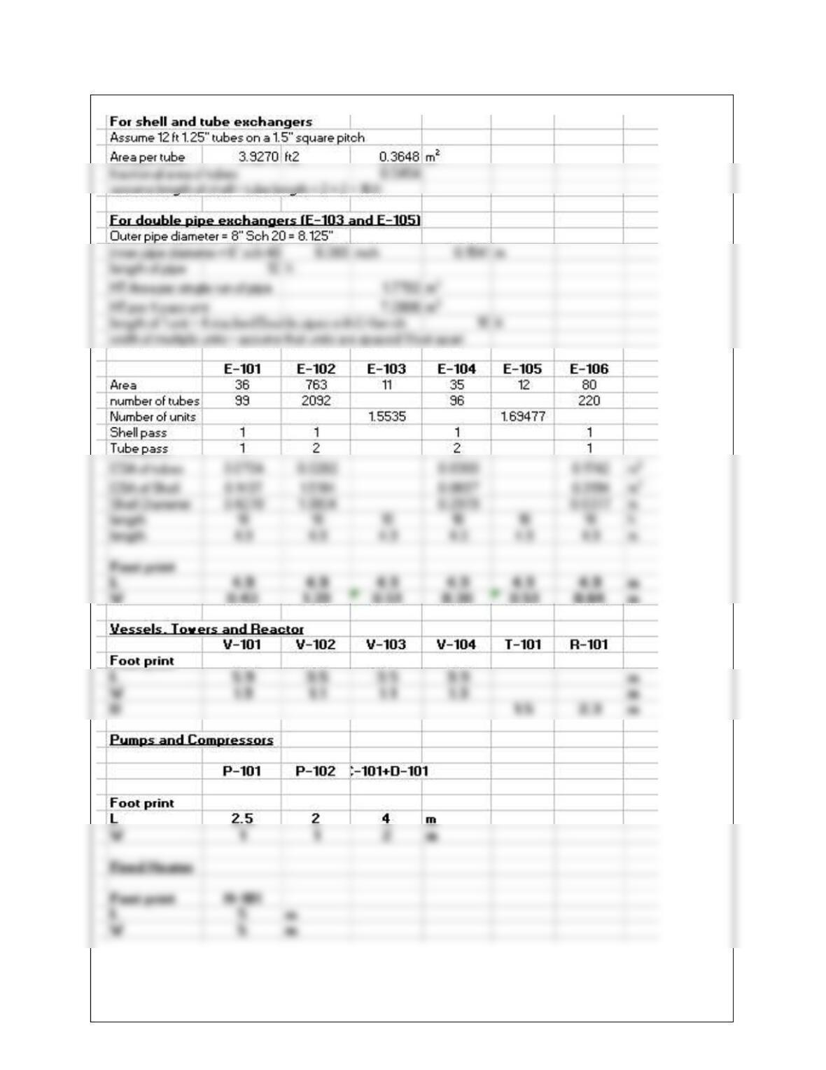
1.4 (1) Clearance for tube bundle removal on a heat exchanger.
(2) NPSH on a pump affects the vertical separation of feed vessel and pump inlet.
1.5 Plastic models are no longer made because they are too expensive and difficult to
1.6 OTS = Operator Training Simulator ITS = Immersive Training Simulator
1.7 Augmented reality refers to a feature of an immersive training system (ITS) where by an
1-2
1.8 Another reason to elevate the bottom of a tower is to provide enough hydrostatic head
driving force to operate a thermosiphon reboiler
1.9 (a) PFD or P&ID
(b) PFD
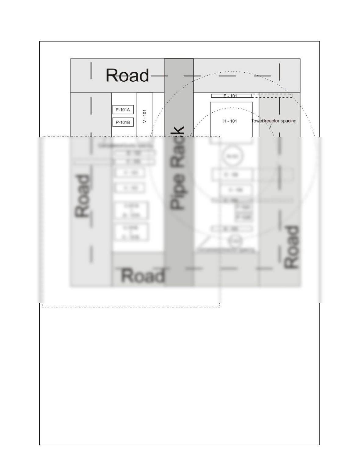
1.10 A pipe rack provides a clear path for piping within and between processes. It keeps piping
1.11 A structure mounted vertical plant layout is preferred when land is at a premium and the
1.12 (a) BFD No change
PFD Efficiency changed on fired heater, resize any heat exchanger used to extract
heat from the flue gas (economizer)
P&ID Resize fuel and combustion air lines and instrumentation for utilities to fired
1.13 (a) A new vessel number need not be used, but it would be good practice to add a letter to
donate a new vessel, e.g. V-203 V-203N. This will enable an engineer to locate the
1-3
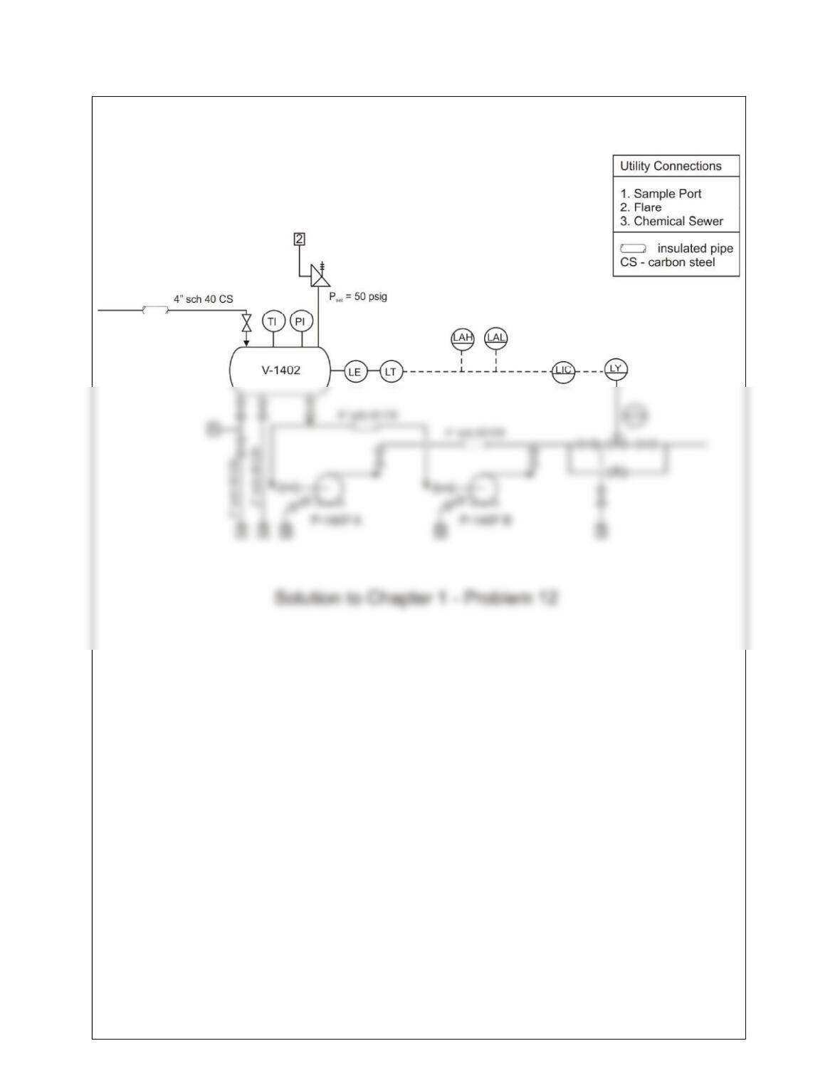
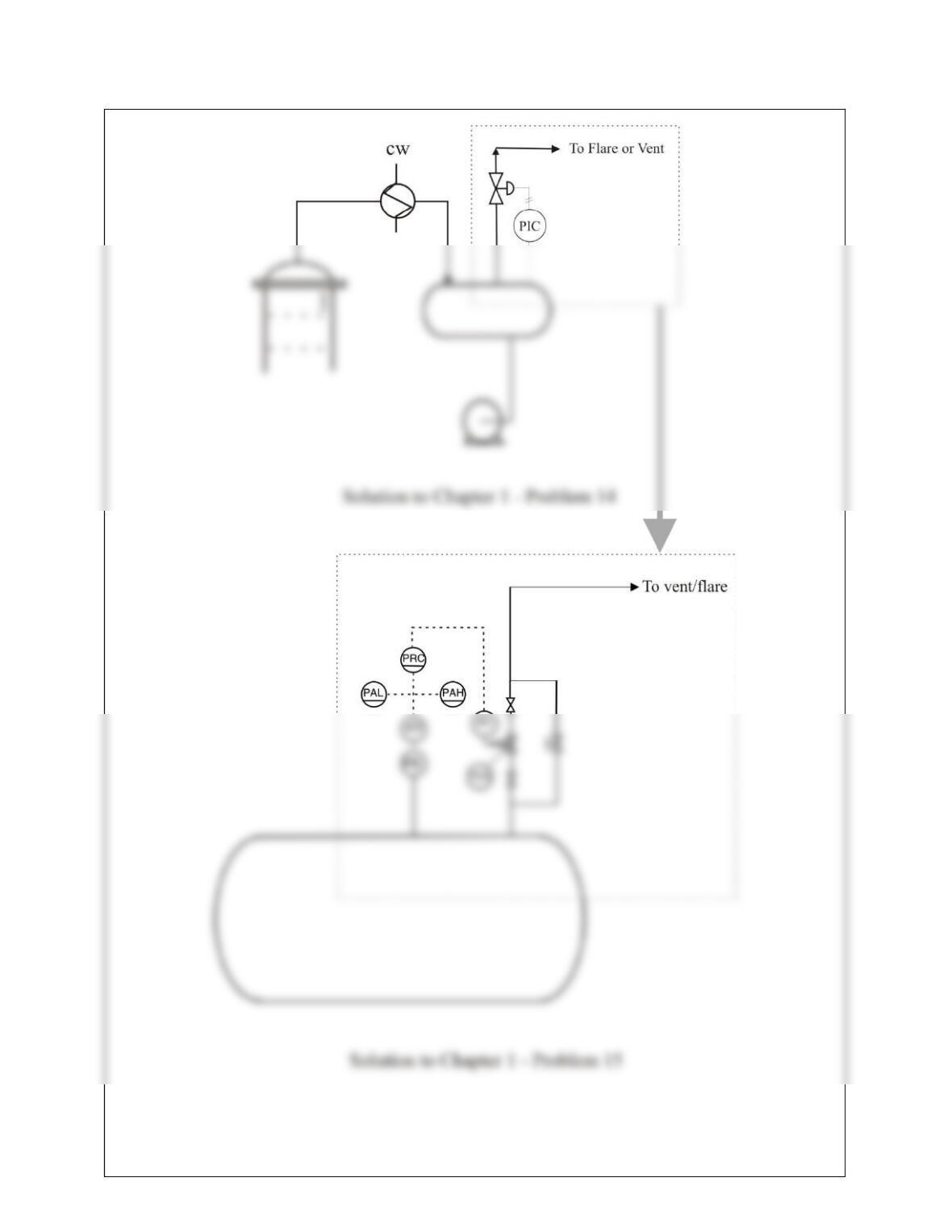
1.14
1-4
1.15 (a) (i) Open globe valve D
(ii) Shut off gate valves A and C
(iii)Open gate valve E and drain contents of isolated line to sewer
1-5
1.16
1.17
1-6
1.18 (a) For a pump with a large NPSH the vertical distance between the feed vessel and the
pump inlet must be large in order to provide the static head required to avoid cavitating the
pump.
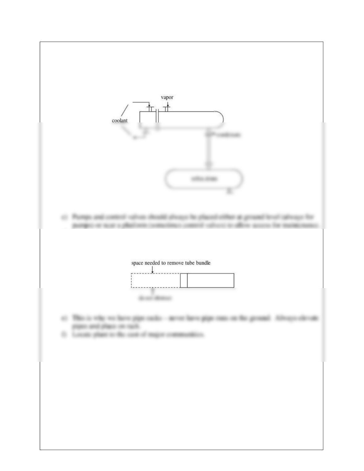
b) Place the overhead condenser vertically above the reflux drum the bottom shell
outlet on the condenser should feed directly into the vertical drum.
d) Arrange shell and tube exchangers so that no other equipment or structural steel
impedes the removal of the bundle.
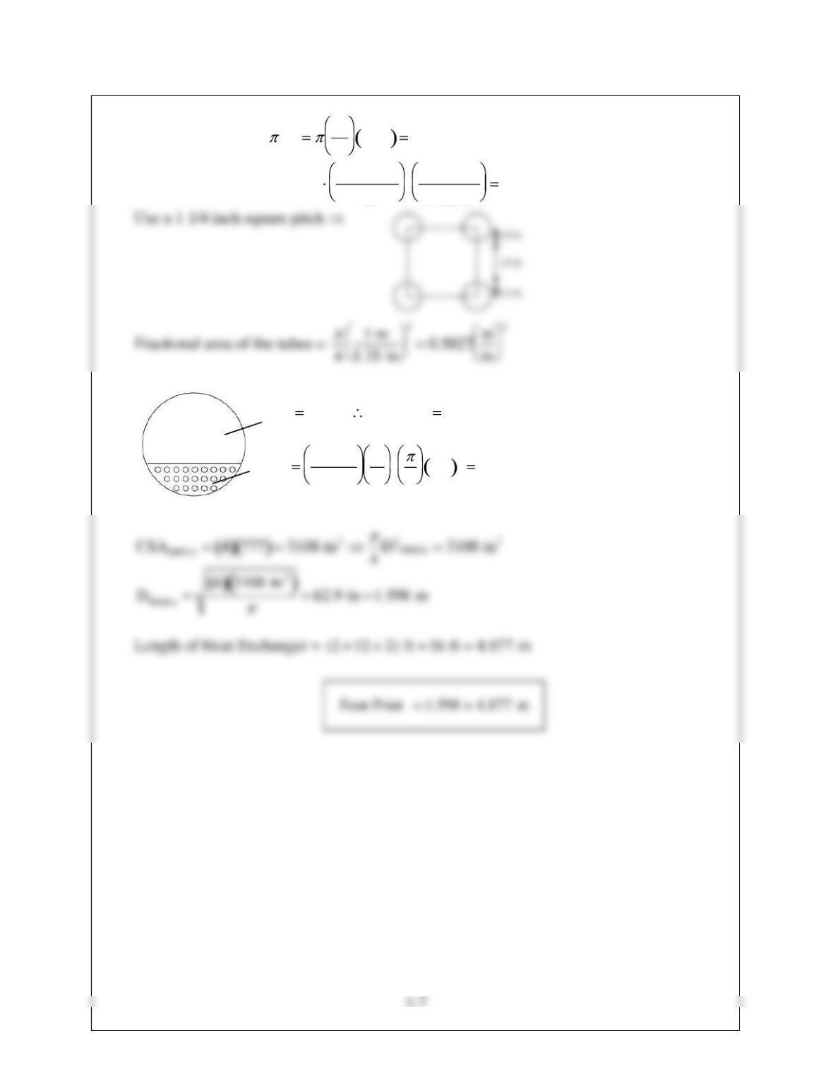
1.19 HT area of 1 tube = DL 1
12 12 ft 3.142 ft2
Number of tubes = (145 m2)3.2808 ft
m
21
3.142 ft2497 tubes
AVAP 3 ALIQ CSASHELL 4
ALIQ
ALIQ
497
0.5027
in
m
2
41 m 2777 in2
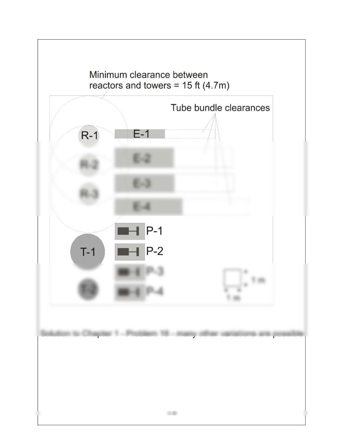
1.20 From Table 1.11 towers and reactors should have a minimum separation of 15 feet or 4.6
meters. No other restrictions apply. See sketch for details.
1-9
1.21
1-10
1.22
1-11
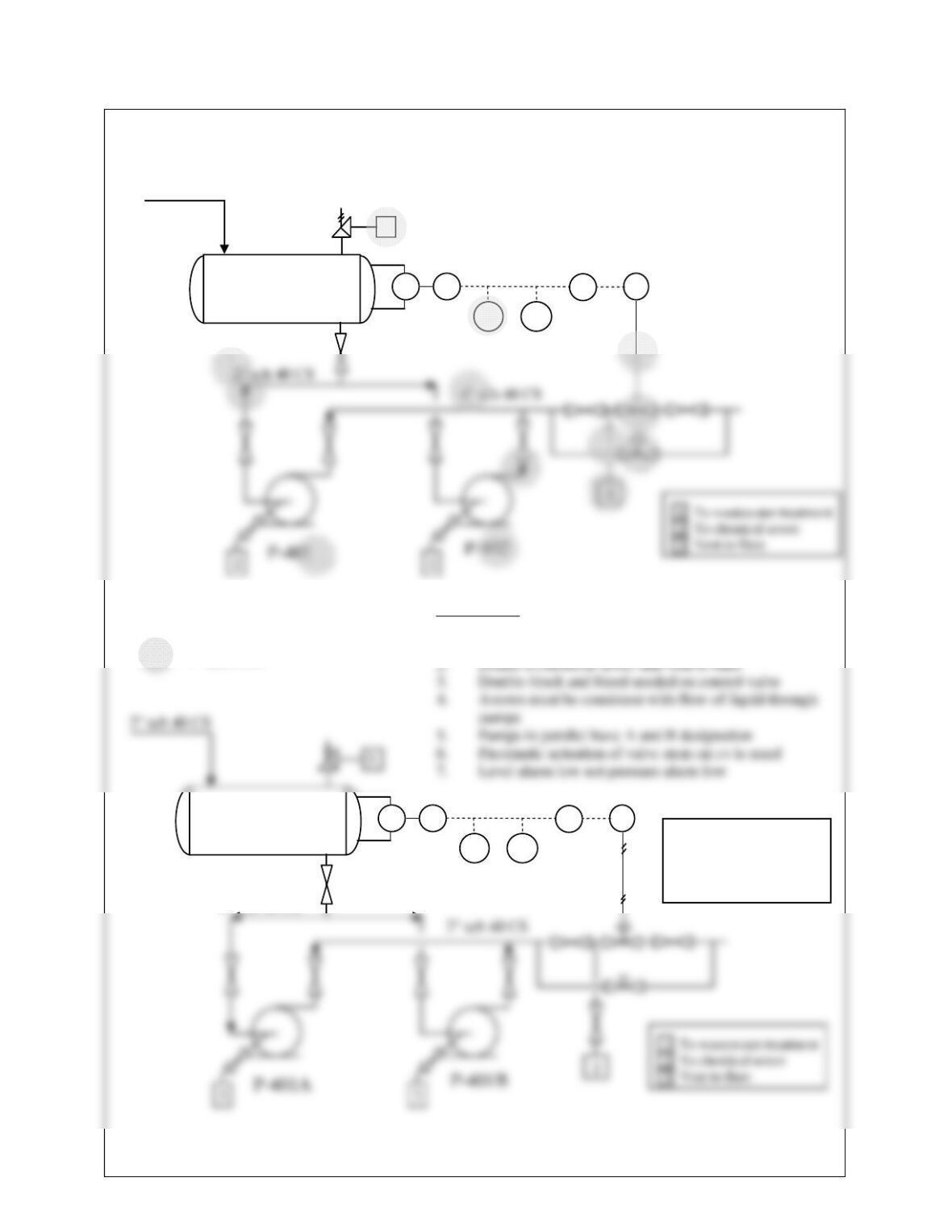
1.23 (a) A temperature (sensing) element (TE) in the plant is connected via a capillary line to
a temperature transmitter (TT) also located in the plant. The TT sends an electrical
signal to a temperature indicator controller (TIC) located on the front of a panel in the
1-12
1.24
LE LT LIC
PAL LAH
LY
1
V-302
2 sch 40 CS
LE LT LIC
LAL LAH
LY
V-302
4 sch 40 CS
= Erro
r
List of Errors
1. Pipe inlet always larger than pipe outlet due to NPSH
issues
Corrected
P&ID