PV[39] = pixel_bits [38*pixel_size + 1: 39*pixel_size];
PV[40] = pixel_bits [39*pixel_size + 1: 40*pixel_size];
genvar m;
generate for (m = 1; m <= N_col*M_row; m = m + 1)
begin: FU
if (m ==1) begin HPFU M (Histogram_memory[1], {H_bin_size*N_bins{1’b0}}, PV[1]); end
else
HPFU M (Histogram_memory[m], Histogram_memory [m-1], PV[m]); // Instantiate functional
);
integer k;
reg [1: H_bin_size] Histogram [1: N_bins];
genvar gv_k;
generate
for (gv_k = 1; gv_k <= N_bins; gv_k = gv_k + 1) begin: H_bits
assign Histogram_out [ 1 + (gv_k -1)*H_bin_size : gv_k*H_bin_size] =
Histogram [gv_k] + Histogram_in [1 + (gv_k -1)*H_bin_size : gv_k*H_bin_size];
end
endgenerate
always @ (PV) begin
for (k = 1; k <= N_bins; k = k + 1) Histogram[k] = 0;
wire [1: H_bin_size*N_bins] Histogram_bits;
reg [1: pixel_size * N_col * M_row] pixel_bits;
Image_Histogram_Processor_Baseline M0 (Histogram_bits, pixel_bits);
wire [H_bin_size: 1] Level1 = Histogram_bits [1: H_bin_size];
wire [H_bin_size: 1] Level2 = Histogram_bits [1 + H_bin_size: 2*H_bin_size];
initial #14000 $finish;
initial fork
begin: Image_Pattern_1
pixel_bits = { 8’hff, 8’hff, 8’hff, 8’hff, 8’h00, 8’h00, 8’h00, 8’h00,
8’hff, 8’hff, 8’hff, 8’hff, 8’h00, 8’h00, 8’h00, 8’h00,
8’hff, 8’hff, 8’hff, 8’hff, 8’h00, 8’h00, 8’h00, 8’h00,
8’h00, 8’h00, 8’h00, 8’h00, 8’hff, 8’hff, 8’hff, 8’hff,
8’hff, 8’hff, 8’hff, 8’hff, 8’h00, 8’h00, 8’h00, 8’h00};
end
#1000 begin: Image_Pattern_3_Cross
pixel_bits = { 8’h00, 8’h00, 8’hff, 8’hff, 8’hff, 8’hff, 8’h00, 8’h0,
8’h00, 8’h00, 8’hff, 8’hff, 8’hff, 8’hff, 8’h00, 8’h00,
8’hff, 8’hff, 8’hff, 8’hff, 8’hff, 8’hff, 8’hff, 8’hff,
8’hff, 8’hff, 8’hff, 8’hff, 8’hff, 8’hff, 8’hff, 8’hff,
8’h1f, 8’h3f, 8’h5f, 8’h8f, 8’h9f, 8’hbf, 8’hdf, 8’hff,
8’h1f, 8’h3f, 8’h5f, 8’h8f, 8’h9f, 8’hbf, 8’hdf, 8’hff,
8’h1f, 8’h3f, 8’h5f, 8’h8f, 8’h9f, 8’hbf, 8’hdf, 8’hff,
8’h1f, 8’h3f, 8’h5f, 8’h8f, 8’h9f, 8’hbf, 8’hdf, 8’hff};
end
#2500 begin: Image_Pattern_6_Mixed_Values
pixel_bits = { 8’h1f, 8’h3f, 8’h5f, 8’h8f, 8’h9f, 8’hbf, 8’hdf, 8’hff,
8’h1f, 8’h3f, 8’h5f, 8’h8f, 8’h9f, 8’hbf, 8’hdf, 8’hff,
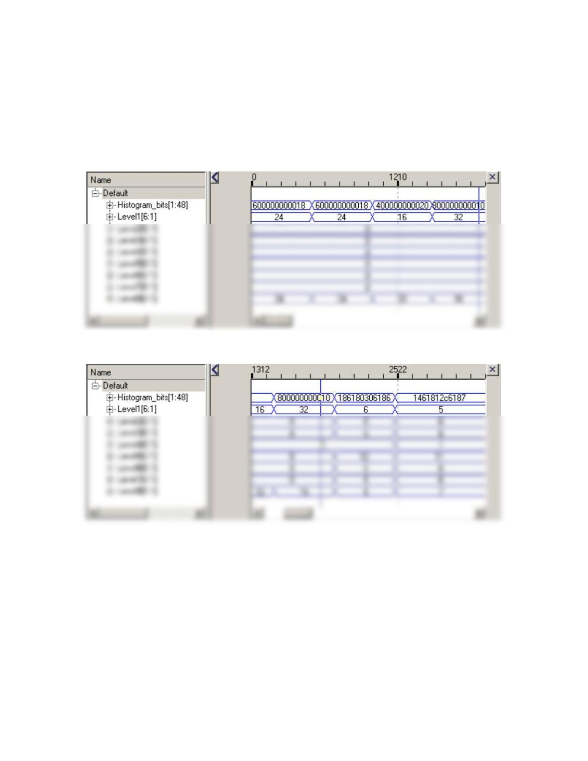
The results of processing the set of images in the testbench are shown below. Note that
the output of the processor is formed without propagation delay because the model is a 0-
delay model. In every case, the sum of the histogram levels is 48, the size of the array.
These results will be a point of comparison with the alternative designs in the next
sections of the problem.
(2) Single Processor Realization The baseline machine has one FU for each pixel, so this
FU-rich implementation corresponds to one extreme of the hardware resource spectrum.
At the other extreme, requiring less physical resources, is a sequential machine using
only one FU. This machine processes the mage sequentially, one pixel at a time, taking
Like the processor of the baseline machine, the FU of a sequential machine could consist
of a comparator that asserts an output bit corresponding to a histogram-level bin, and an
adder that adds the output of the comparator to an input consisting of the histogram from
its left-adjacent neighbor (computed in the previous cycle) resulting in a single thread of
computational activity to process the entire image. As an alternative to using a
The figures below show (1) registers of the datapath unit of our implementation, (2) a
block diagram showing the interface signals between the control unit and the datapath,
and (3) the ASMD chart for the machine’s Verilog model.

HDPU
Clr_index
Update_H
HP_Control_unit
Go
Ready
Busy
Valid
Histogram_bits[1: H_bin_size*N_bins]
i_lt_max
Incr_index
Clr_regs
Ld_image
);
wire Clr_index, Incr_index, Clr_regs, Ld_image, Update_H;
HP_Control_Unit M0
(Ready, Busy, Valid, Clr_index, Incr_index, Clr_regs, Ld_image, Update_H, Go, i_lt_max, clk,
reset);
HPDU M1
(Histogram_bits, i_lt_max, pixel_bits, Clr_index, Incr_index, Clr_regs, Ld_image, Update_H, clk,
reset);
endmodule
assign Ready = (state == S_idle);
assign Busy = (state == S_running);
assign Valid = (state == S_done);
always @ (posedge clk) if (reset) state <= S_idle; else state <= next_state;
always @ (state, Go, i_lt_max) begin
Ld_image = 0; Clr_index = 0; Incr_index = 0; Update_H = 0; Clr_regs = 0; next_state = S_idle;
case (state)
S_idle: if (Go) next_state = S_loading;
// Histogram Processor Datapath Unit
module HPDU #(parameter
pixel_size = 8, H_ptr_size = 4, H_bin_size = 6, index_size = 6, N_bins = 8, N_col = 8, M_row =
6,
integer k;
genvar gv_k;
generate
for (gv_k = 1; gv_k <= N_bins; gv_k = gv_k + 1) begin: H_bits
assign Histogram_bits [1 + (gv_k -1)*H_bin_size : gv_k*H_bin_size] = Histogram [gv_k];
end
endgenerate
assign i_lt_max = (index < N_col*M_row);
/*
always @ (index, pixel_buffer)
case (index)
1: PV = pixel_buffer [1: pixel_size];
2: PV = pixel_buffer [pixel_size + 1: 2*pixel_size];
3: PV = pixel_buffer [2*pixel_size + 1: 3*pixel_size];
4: PV = pixel_buffer [3*pixel_size + 1: 4*pixel_size];
5: PV = pixel_buffer [4*pixel_size + 1: 5*pixel_size];
6: PV = pixel_buffer [5*pixel_size + 1: 6*pixel_size];
17: PV = pixel_buffer [16*pixel_size + 1: 17*pixel_size];
18: PV = pixel_buffer [17*pixel_size + 1: 18*pixel_size];
19: PV = pixel_buffer [18*pixel_size + 1: 19*pixel_size];
20: PV = pixel_buffer [19*pixel_size + 1: 20*pixel_size];
21: PV = pixel_buffer [20*pixel_size + 1: 21*pixel_size];
28: PV = pixel_buffer [27*pixel_size + 1: 28*pixel_size];
29: PV = pixel_buffer [28*pixel_size + 1: 29*pixel_size];
30: PV = pixel_buffer [29*pixel_size + 1: 30*pixel_size];
31: PV = pixel_buffer [30*pixel_size + 1: 31*pixel_size];
32: PV = pixel_buffer [31*pixel_size + 1: 32*pixel_size];
33: PV = pixel_buffer [32*pixel_size + 1: 33*pixel_size];
34: PV = pixel_buffer [33*pixel_size + 1: 34*pixel_size];
default PV = 0;
endcase
*/
always @ (PV) begin
H_ptr = 0;
if ((0 <= PV) && (PV < L1)) begin H_ptr = 1; end else
always @ (posedge clk)
if (reset || Clr_regs) for (k = 1; k <= N_bins; k = k + 1) Histogram [k] = 0;
else if (Update_H) Histogram [H_ptr] <= Histogram [H_ptr] + 1;
endmodule
module t_Image_Histogram_Processor # (parameter
pixel_size = 8, H_bin_size = 6, N_bins = 8, N_col = 8, M_row = 6, N_Level = 8, index_size =
6)();
wire [1: H_bin_size*N_bins] Histogram_bits;
wire Ready, Busy, Valid;
reg [1: pixel_size * N_col * M_row] pixel_bits;
reg Go, clk, reset;
initial fork
reset = 1; #10 reset = 0;
#50 Go = 1;
//#60 Go = 0;
join
end
#500 begin: Image_Pattern_2
pixel_bits = { 8’h00, 8’h00, 8’h00, 8’h00, 8’hff, 8’hff, 8’hff, 8’hff,
8’h00, 8’h00, 8’h00, 8’h00, 8’hff, 8’hff, 8’hff, 8’hff,
8’h00, 8’h00, 8’h00, 8’h00, 8’hff, 8’hff, 8’hff, 8’hff,
8’hff, 8’hff, 8’hff, 8’hff, 8’h00, 8’h00, 8’h00, 8’h00,
8’hff, 8’hff, 8’hff, 8’hff, 8’h00, 8’h00, 8’h00, 8’h00,
8’hff, 8’hff, 8’hff, 8’hff, 8’h00, 8’h00, 8’h00, 8’h00};
end
#1000 begin: Image_Pattern_3_Cross
pixel_bits = { 8’h00, 8’h00, 8’hff, 8’hff, 8’hff, 8’hff, 8’h00, 8’h0,
8’hff, 8’hff, 8’h00, 8’h00, 8’h00, 8’h00, 8’hff, 8’hff};
end
#2000 begin: Image_Pattern_5_Graduated_Left_to_Right
pixel_bits = { 8’h1f, 8’h3f, 8’h5f, 8’h8f, 8’h9f, 8’hbf, 8’hdf, 8’hff,
8’h1f, 8’h3f, 8’h5f, 8’h8f, 8’h9f, 8’hbf, 8’hdf, 8’hff,
8’h1f, 8’h3f, 8’h5f, 8’h8f, 8’h9f, 8’hbf, 8’hdf, 8’hff,
8’h1f, 8’h3f, 8’h5f, 8’h8f, 8’h9f, 8’hbf, 8’hdf, 8’hff,
join
endmodule
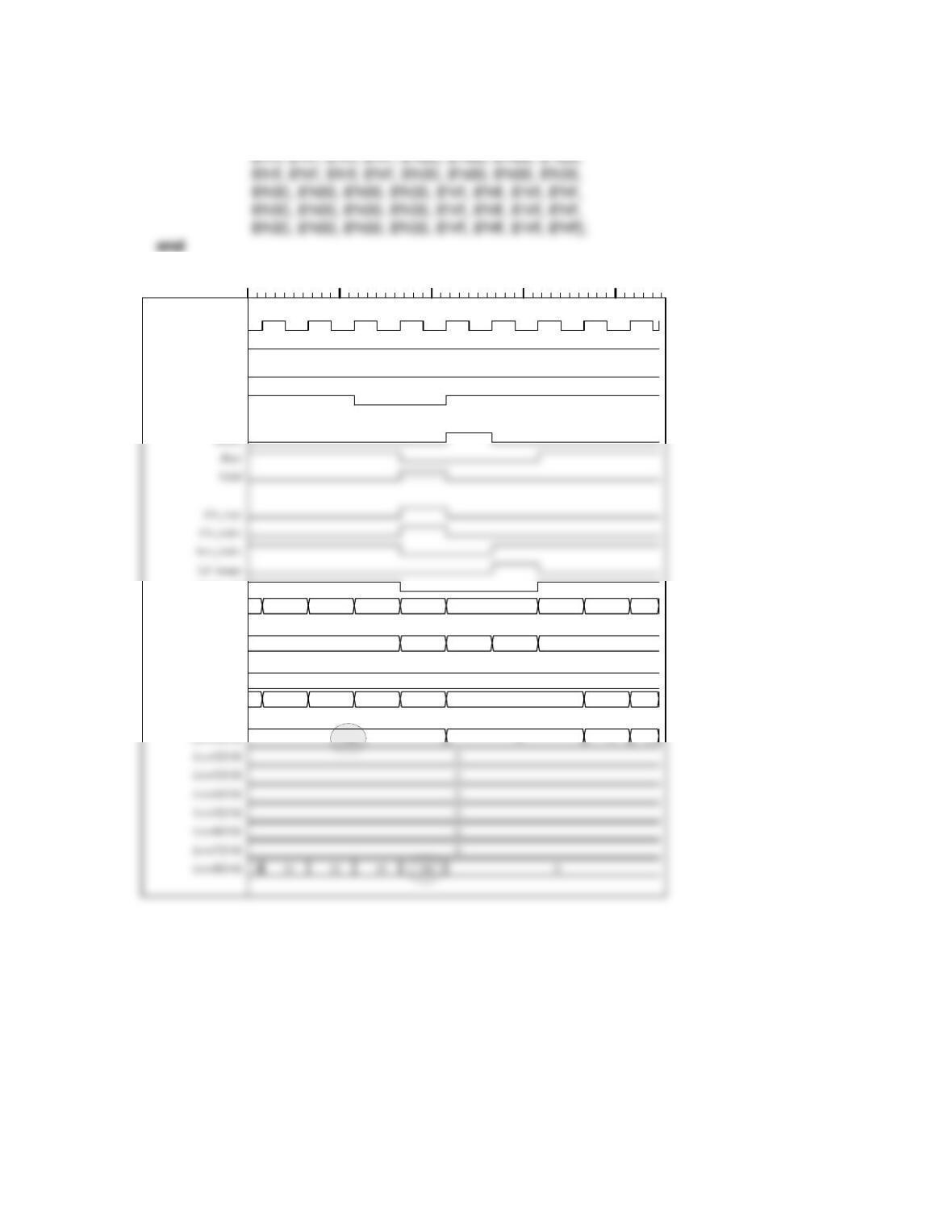
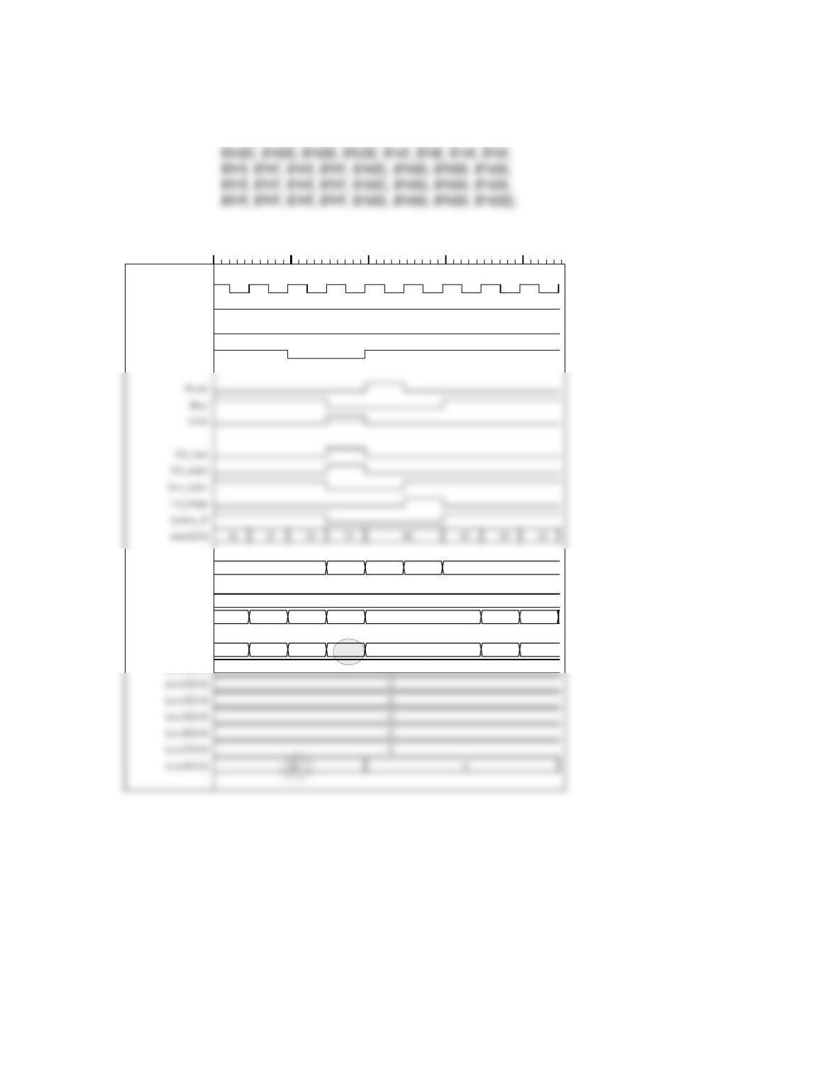
The output of the processor is given below for the same 6 patterns that were used in the
testbench of the baseline machine. As a check, note that the sum of the histogram values
Image_Pattern_1
pixel_bits = { 8’hff, 8’hff, 8’hff, 8’hff, 8’h00, 8’h00, 8’h00, 8’h00,
512 532 552 572 592
2d 2e
2f
2
30
24
31
3 0
00
1
000000000000
01
0
02
1 2
03
00000000ffffffff00000000ffffffff00000000ffffffffffffffff00000000ffffffff00000000ffffffff00000000
2
Name
clk
reset
Go
i_lt_max
Ready
Update_H
index[5:0]
state[1:0]
pixel_bits[1:384]
Histogram_bits[1:48]
Level1[5:0]
Image_Pattern_2
pixel_bits = { 8’h00, 8’h00, 8’h00, 8’h00, 8’hff, 8’hff, 8’hff, 8’hff,
8’h00, 8’h00, 8’h00, 8’h00, 8’hff, 8’hff, 8’hff, 8’hff,
1026 1046 1066 1086 1106
21
22
2
23
24
3 0
1
000000000000
0
1
0
2
0000ffffffff00000000ffffffff0000 ffffffffffffffffffffffffffffffff0000ffffffff00000000ffffffff0000
2
Name
clk
reset
Go
i_lt_max
state[1:0]
pixel_bits[1:384]
Histogram_bits[1:48]
Level1[5:0]
Level2[5:0]
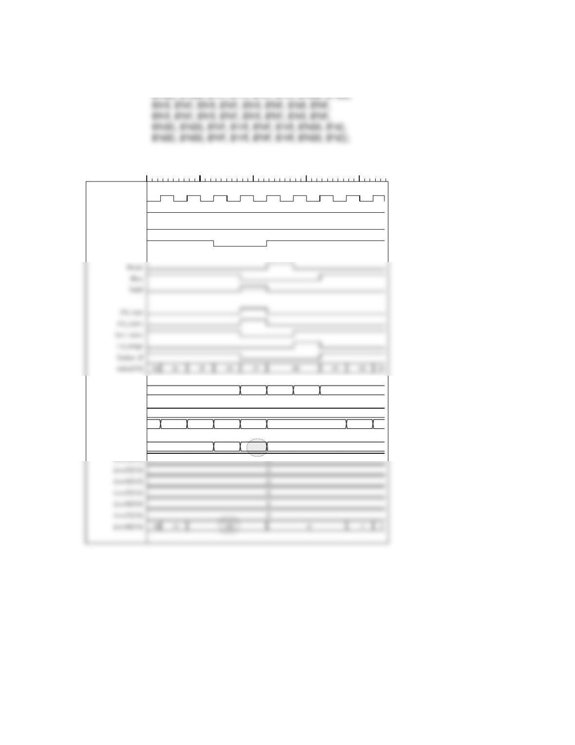
Image_Pattern_3_Cross
pixel_bits = { 8’h00, 8’h00, 8’hff, 8’hff, 8’hff, 8’hff, 8’h00, 8’h0,
1530 1550 1570 1590 1610
14
2
15
16
3 0
1
000000000000
0
2
Name
clk
reset
Go
i_lt_max
state[1:0]
pixel_bits[1:384]
Histogram_bits[1:48]
Level1[5:0]
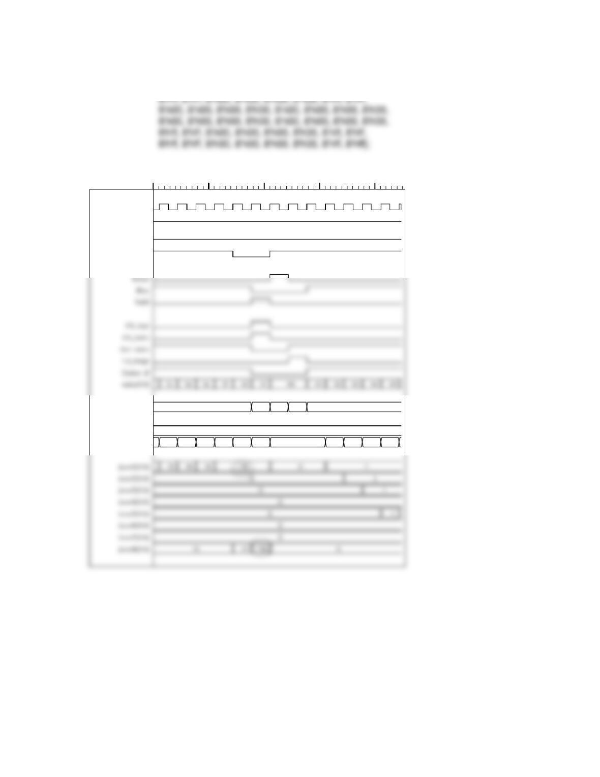
Image_Pattern_4_Bar_Cross
pixel_bits = { 8’hff, 8’hff, 8’h00, 8’h00, 8’h00, 8’h00, 8’hff, 8’hff,
2022 2052 2082 2112 2142
2
3 0
1
000000000000
1f 3f 5f 8f9 f b f d f f f1f 3f 5f 8f 9 f b f df f f1f 3f 5f 8f 9 f b f df f f1f 3f 5f 8f 9 f b f df f f1f 3f 5f 8f9 f b f d f f f1f 3f 5f 8f 9 f b f d f f f
2
Name
clk
reset
Go
i_lt_max
state[1:0]
pixel_bits[1:384]
Histogram_bits[1:48]
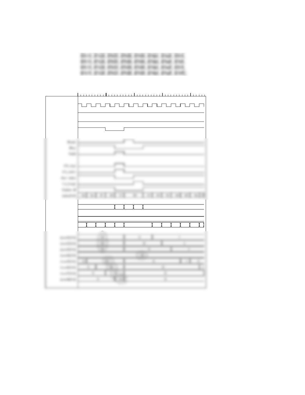
Image_Pattern_5_Graduated_Left_to_Right
pixel_bits = { 8’h1f, 8’h3f, 8’h5f, 8’h8f, 8’h9f, 8’hbf, 8’hdf, 8’hff,
8’h1f, 8’h3f, 8’h5f, 8’h8f, 8’h9f, 8’hbf, 8’hdf, 8’hff,
2546 2576 2606 2636 2666
2
3 0
1
000000000000
1f 3f 5f 8f9 f b f d f f f1f 3f 5f 8f 9 f b f d ff f1f 3f 5f 8f 9 f b f d f f f1f 3f5f 8f 9 f b f d f f f1f 3f 5f 8f9 f b f d f f f 2 0 4 0 6 0 8 0a0c0e0ff
2
Name
clk
reset
Go
i_lt_max
state[1:0]
pixel_bits[1:384]
Histogram_bits[1:48]
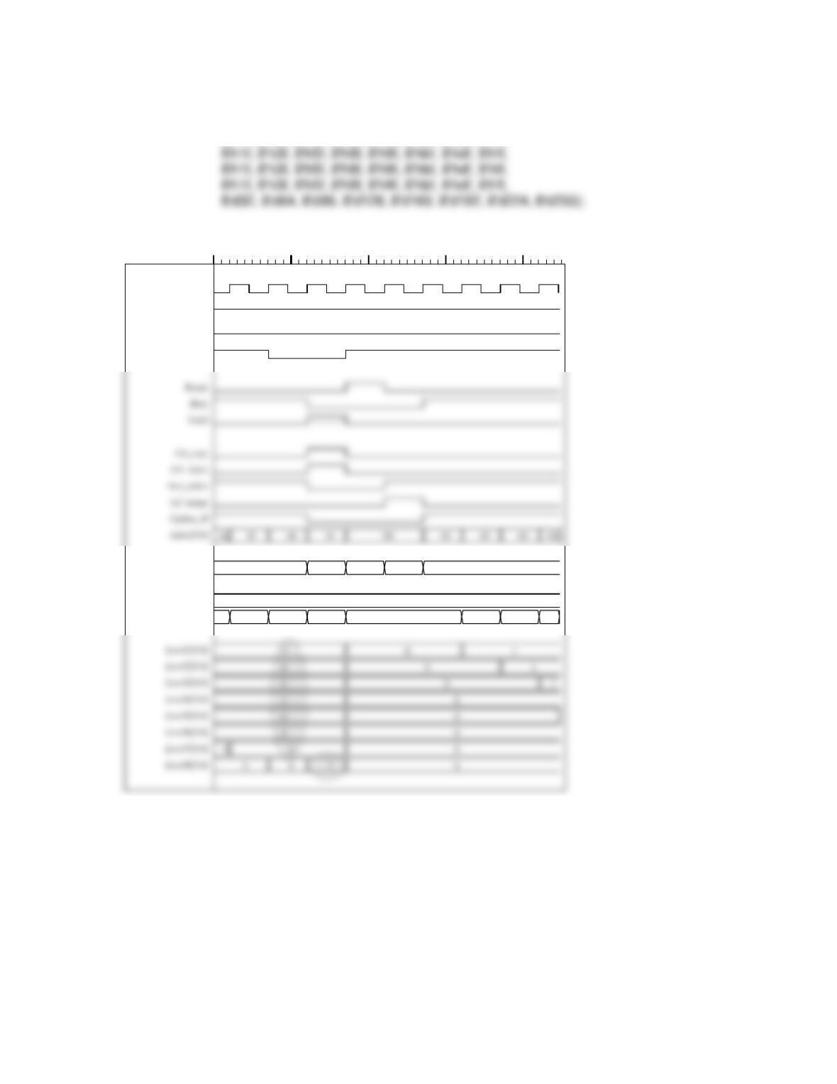
Image_Pattern_6_Mixed_Values
pixel_bits = { 8’h1f, 8’h3f, 8’h5f, 8’h8f, 8’h9f, 8’hbf, 8’hdf, 8’hff,
8’h1f, 8’h3f, 8’h5f, 8’h8f, 8’h9f, 8’hbf, 8’hdf, 8’hff,
3071 3091 3111 3131 3151
2
3 0
1
000000000000
1f 3f 5f 8f9 f b f d f f f1f 3f 5f 8f 9 f b f d ff f1f 3f 5f 8f 9 f b f d f f f1f 3f5f 8f 9 f b f d f f f1f 3f 5f 8f9 f b f d f f f 2 0 4 0 6 0 8 0a0c0e0ff
2
Name
clk
reset
Go
i_lt_max
state[1:0]
pixel_bits[1:384]
Histogram_bits[1:48]
(3) Concurrent Processors Realization The DFG of the baseline machine is just one of
many that could produce a histogram of the image. In fact, any thread of dataflow
passing though each and all processors only once will produce the histogram,
independent of the order of the processors – because the addition operation is
commutative and the output of a processor depends on the input from only one other
processor. Given the plethora of architectures, what is a reasonable solution to the
problem of finding the maximum number of processors that can operate concurrently to
produce the histogram?
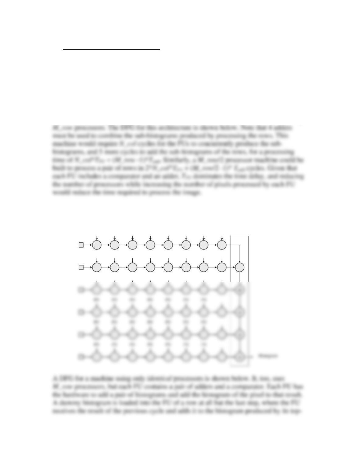
Once alternative to the single-processor machine would be a row-first scheme requiring
PV PV PV PV PV PV PV
PV PV PV PV PV PV PV
PV PV PV PV PV PV PV
+
#Processors = N_row
TH = M_col * TFU + (M_row -1)* Tadd
PV
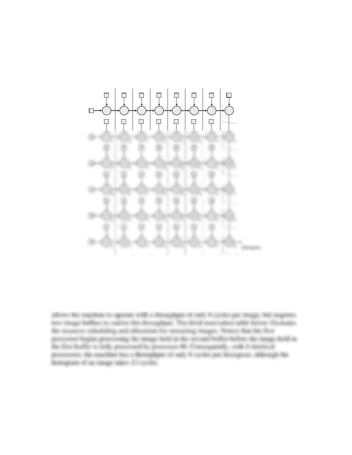
adjacent neighbor. This machine has one more adder and could operate faster than the
M_row processor machine discussed above because the former executes comparison and
a pair of additions in each clock cycle, while the latter machine must have a clock cycle
that accommodates the concurrent formation of a histogram and then an additional
(M_row -1)*Tadd for adding the row histograms.
123456
7
8
12345678
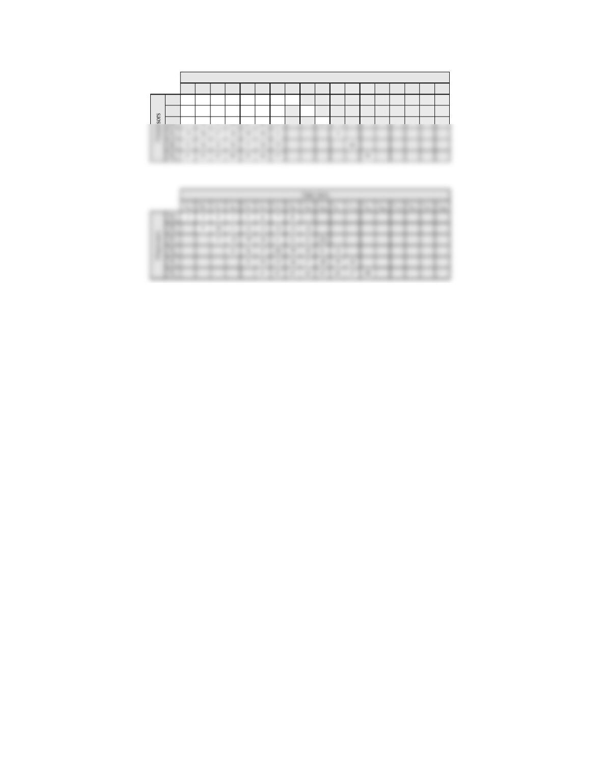
The availability of data in the data flow graph determines the maximum number of
processors that can operate concurrently. In the architecture shown above, 6 processors
are used.
The reservation table for the identical-processor machine is also shown, together with a
reservation table obtained by staggering the dataflow to support streaming images. This
8
16
3
11
4
12
5
13
6
14
7
15
21P1
P2
910
t8t9t10 t11 t12 t13 t15 t16 t17 t18
t3t4t5t6t7t14
t1t2
Time slots