Chap. 9 Stress 8-21
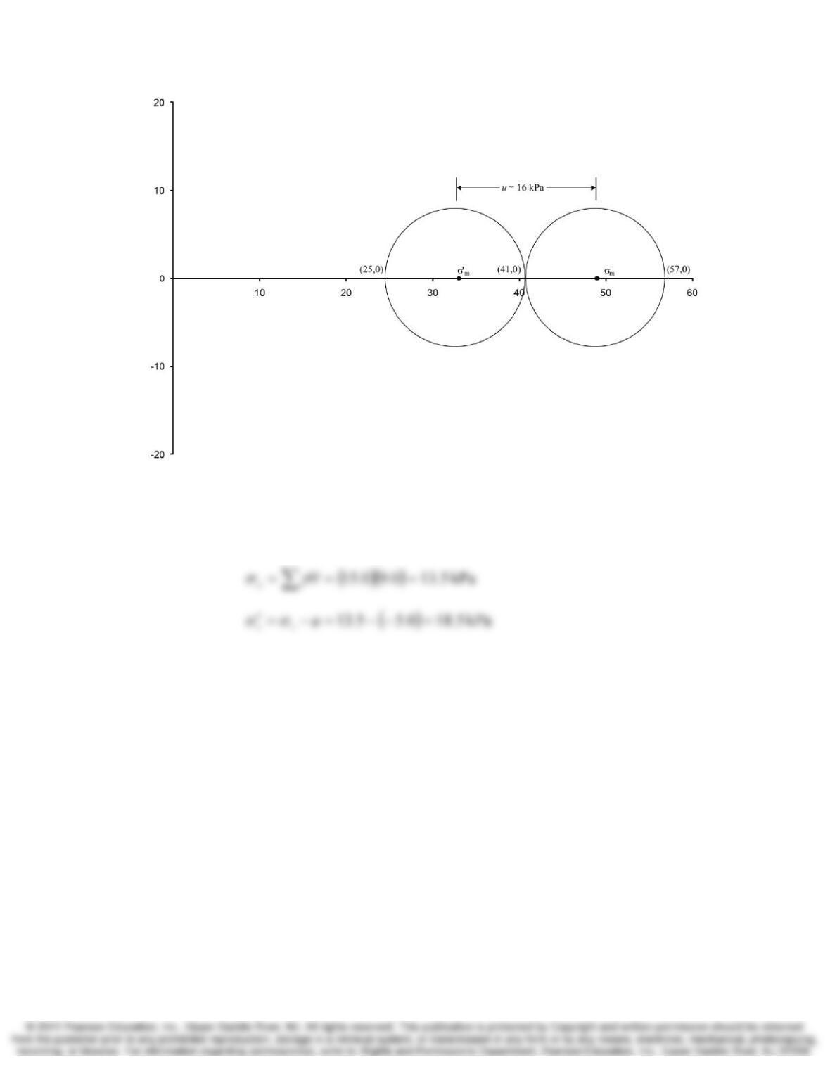
9.23 According to an in-situ soil suction measurement, the pore water pressure at Point C in
Figure 9.11 is −5.0 kPa. Compute the vertical effective stress at this point.
Solution
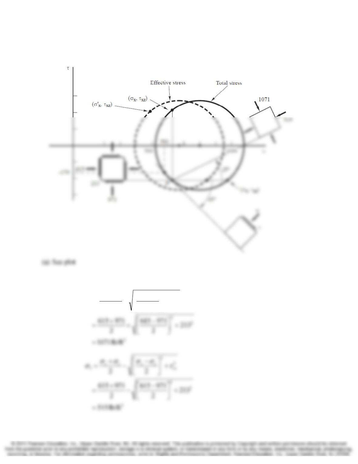
9.24 Use the “overall stresses” data in the x–z plane from Example 9.9 to perform the
following computations:
(a) Draw the Mohr circles for total and effective stresses for this point and identify the
pole and the locations on the circle that represent the vertical and horizontal stresses.
(b) Compute σ1, σ3, σ1′, σ3′, and τmax.
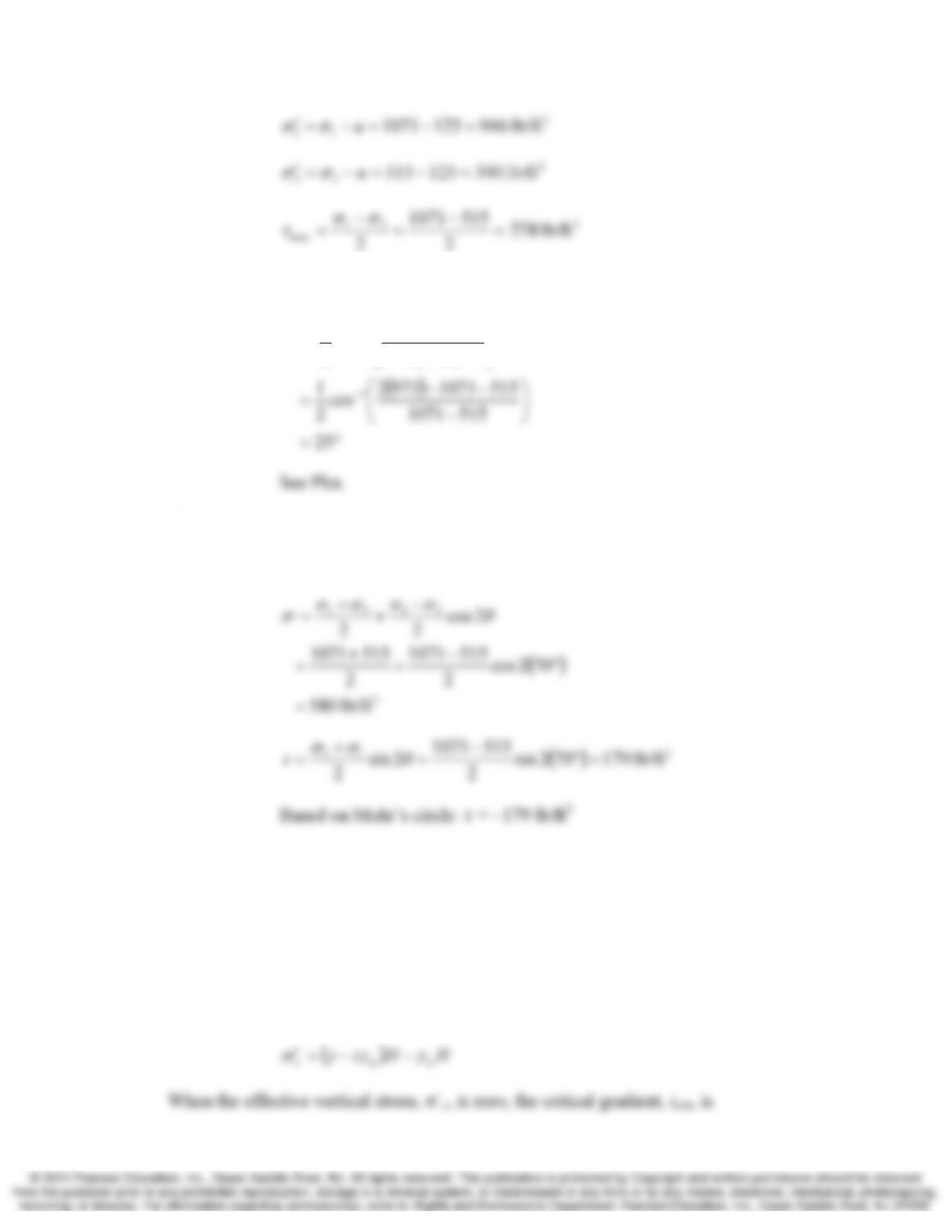
(c) Determine the angle between the major principal stress and the vertical, then prepare
as a sketch showing the orientation of the major and minor principal stresses with
respect to the vertical.
(d) Compute σ, σ′, and τ that act on a plane inclined at an angle of 45° clockwise from
the horizontal.
9-22 Stress Chap. 9
Solution
(b)
2
2
1
22
+
⎥
⎦
⎤
⎢
⎣
⎡−
+
+
=zx
zxzx
τ
σσσσ
σ
Chap. 9 Stress 8-23
(c)
⎟
⎟
⎞
⎜
⎜
⎛
−
−−
=
−
2
cos
2
1
31
1
σσ
σσσ
θ
z
z
(d)
°=+= 702545
θ
Section 9.9 Effective Stress Under Steady State Flow
9.25 Water is flowing vertically upward in a sand with a saturated unit weight of 20 kN/m3. At
what gradient will quick conditions occur?
Solution
Quick condition or quicksand occurs when the effective stress is zero. Using the seepage
force concept and Equation 9.53 and 9.54
9-24 Stress Chap. 9
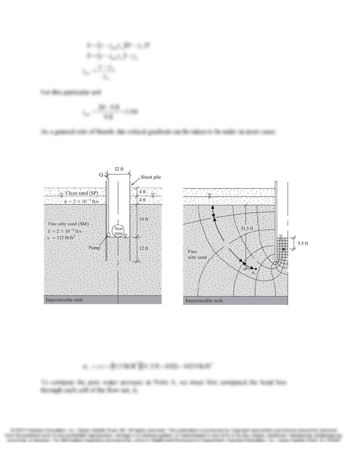
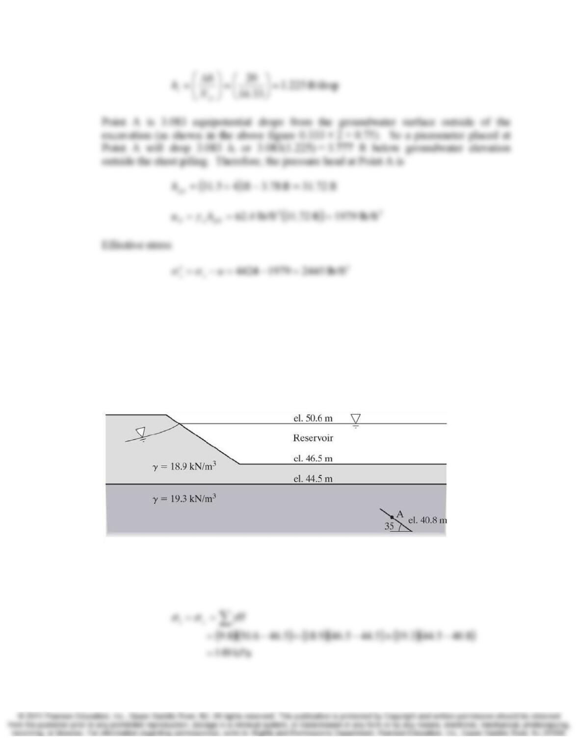
9.26 Compute the total vertical stress, σz, and the effective vertical stress, σ‘z, at Point A in
Figure 8.7.
Figure 8.7 Cross-section of trench for Examples 8.2 and 8.3. The given data is on the
left and the completed flow net is on the right.
Solution
Assuming the unit weight of the clean sand is the same as the silty sand, the total vertical
stress at Point A is
1/3
2
3/4
Chap. 9 Stress 8-25
Comprehensive
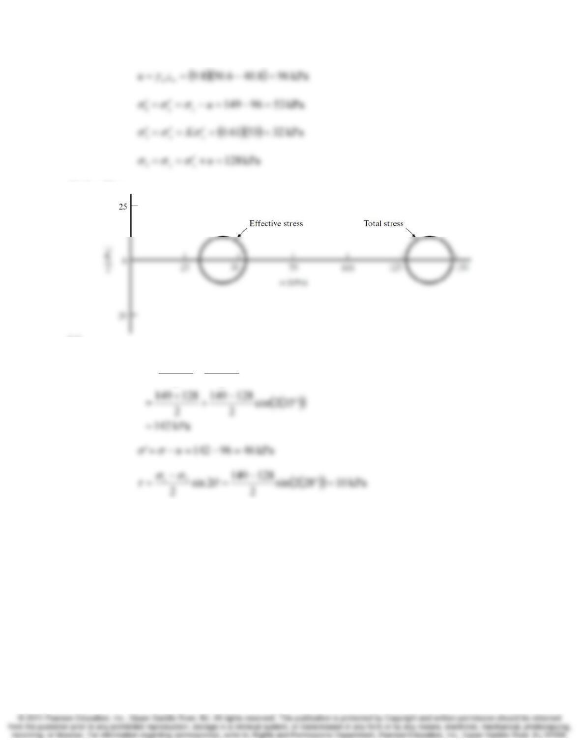
9.27 Using K = 0.61 and assuming the major principal stress acts vertically, compute the
following at Point A in Figure 9.30.
(a) σx, σz, σx′, σz′, σ1, σ3, σ1′, σ3′, u
(b) Mohr circles for total and effective stresses
(c) σ, σ′, and τ on the plane shown in the figure
Figure 9.30 Soil profile for Problem 9.27. el. = elevation.
Solution
(a)
9-26 Stress Chap. 9
(b) See Plot
(c)
2cos
22
3131
−
+
−
=
θ
σ
σ
σ
σ
σ
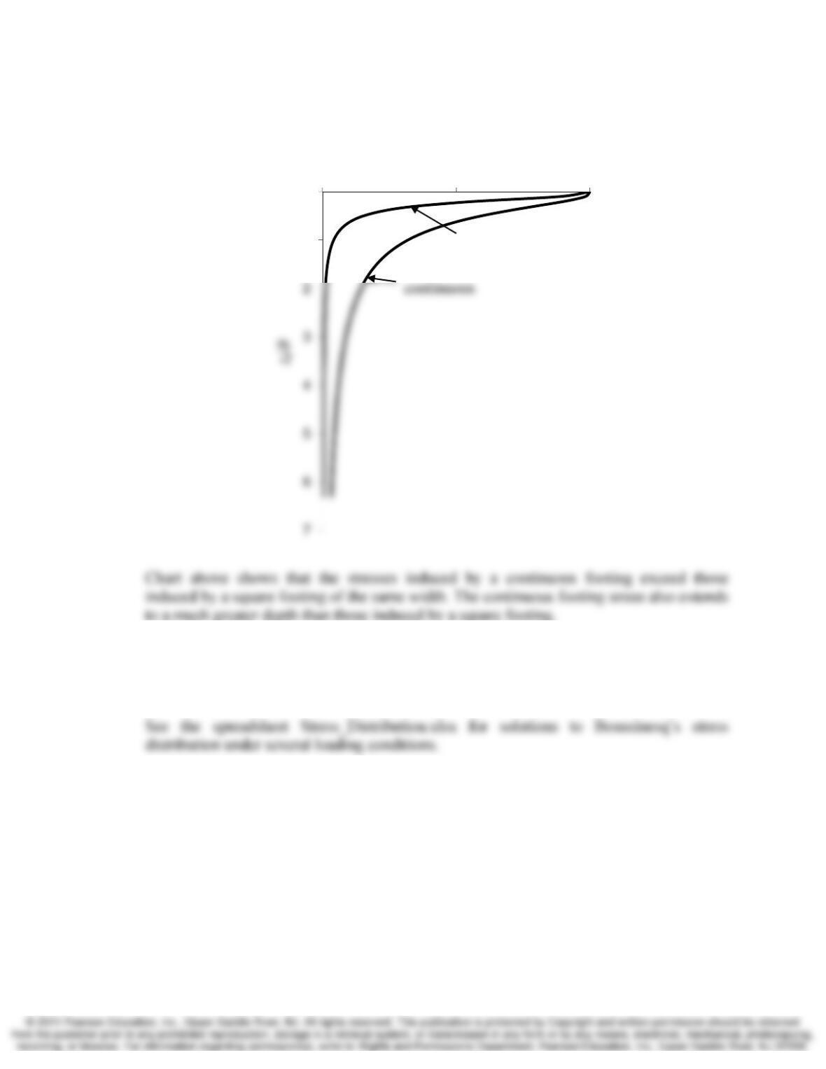
9.28 Using the approximate methods represented by Equations 9.39 and 9.40, create a
spreadsheet to compute the induced vertical stress, Δσz, under the center of a square
loaded area and an infinitely long strip load. Using your spreadsheet develop a plot Δσz
as a function of depth under the center of a square and a strip loads of the same width, B,
with the same applied stress at the surface. Explain the differences between the stress
induced by the square load and the strip load.
γ
σ
σ
σ
σ
σ
σ
Chap. 9 Stress 8-27
Solution
9.29 Create a spreadsheet to compute the induced normal stresses Δσx, Δσy, and Δσz, at any
arbitrary point due to a point load at the ground surface using Boussinesq’s method.
Solution
9.30 A vertical point load P is to be applied to a level ground surface. The underlying soil has
the following pre-construction characteristics:
Groundwater table: 5.5 ft below the ground surface
Unit weight above the groundwater table = 121 lb/ft3
Unit weight below the groundwater table = 124 lb/ft3
K = 0.87
ν
= 0.33
0
1
00.51
Iσ
square
9-28 Stress Chap. 9
The horizontal total stress, σx, at a point 8 ft below the ground surface and 3 ft east of the
point of load application must not exceed 1000 lb/ft2. Compute the maximum allowable
value of P.
Solution
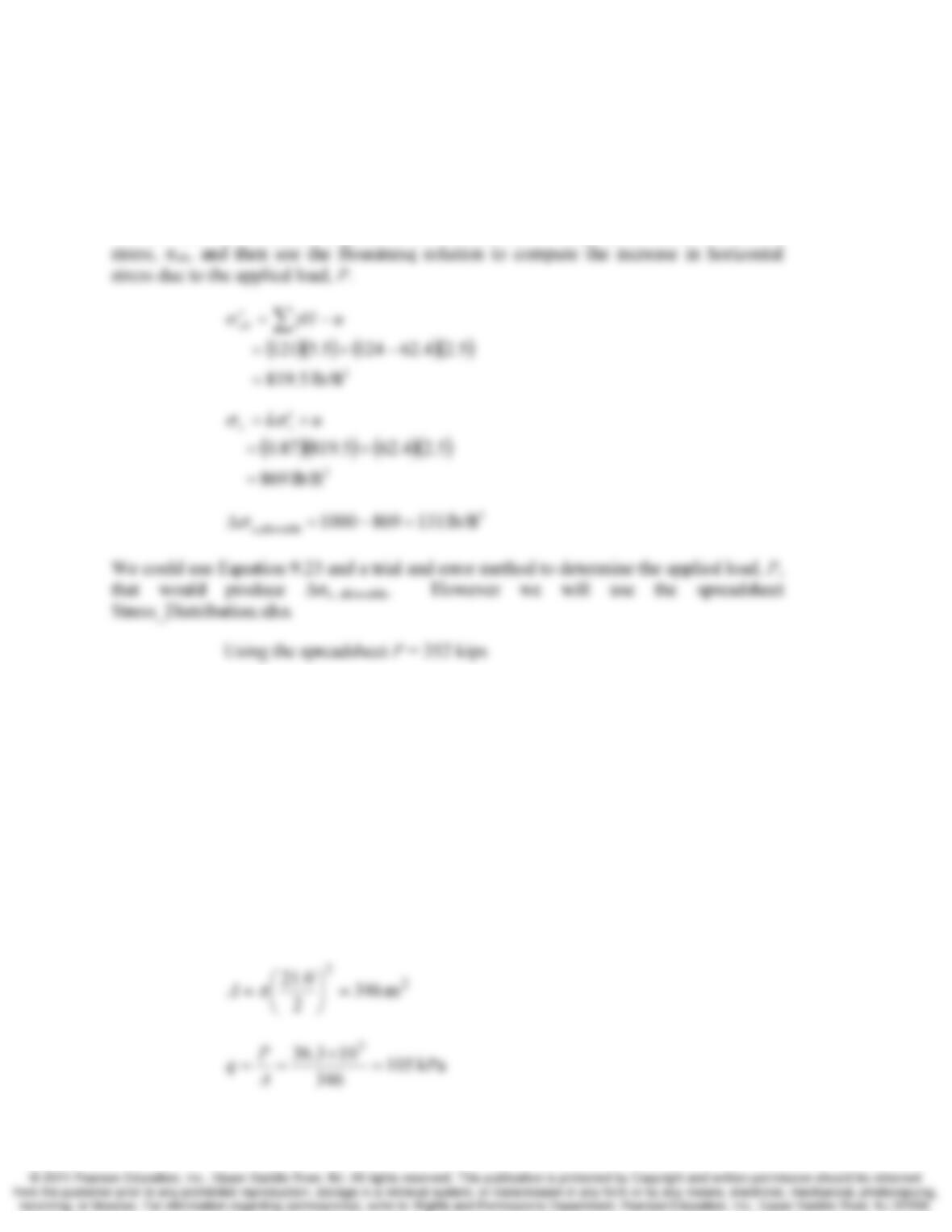
We will use the lateral earth pressure coefficient, K, to compute the initial horizontal
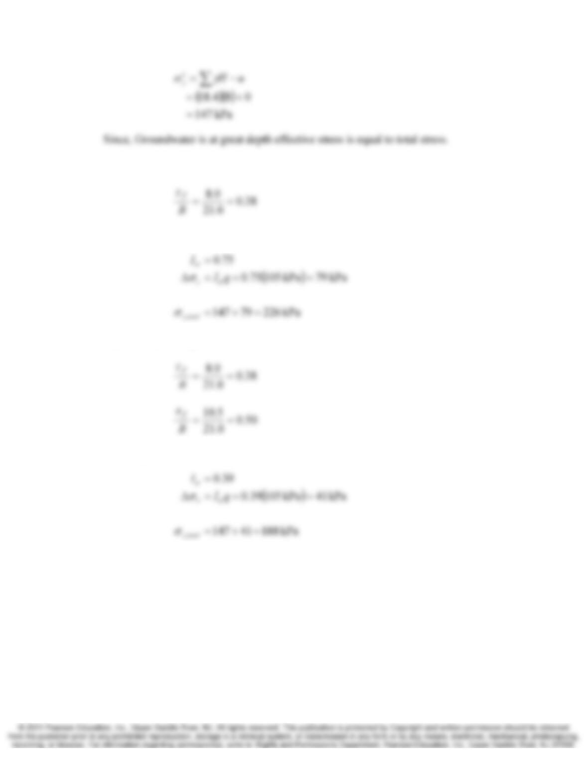
9.31 A 21.0 m diameter oil tank is to be built on a soil that has γ = 18.4 kN/m3, K = 0.60, and
ν = 0.40. The tank and its contents have a total mass of 3.70×10⁶ kg, and the bottom of
the tank is flush with the ground surface. The groundwater table is at a great depth.
Compute the geostatic vertical total and effective stress, the induce vertical stress and
final total and effective vertical stresses for following two points:
(d) 8.0 m below the center of the tank
(e) 8.0 m below the east edge of the tank.
Solution
(
)
(
)
kN 1036.3m/s 9.8kg 103.7 326 ×=×== MgP
Chap. 9 Stress 8-29
(a) 8.0m below center of tank.
From Figure 9.13:
(b) 8.0m below edge of tank.
From Figure 9.13:
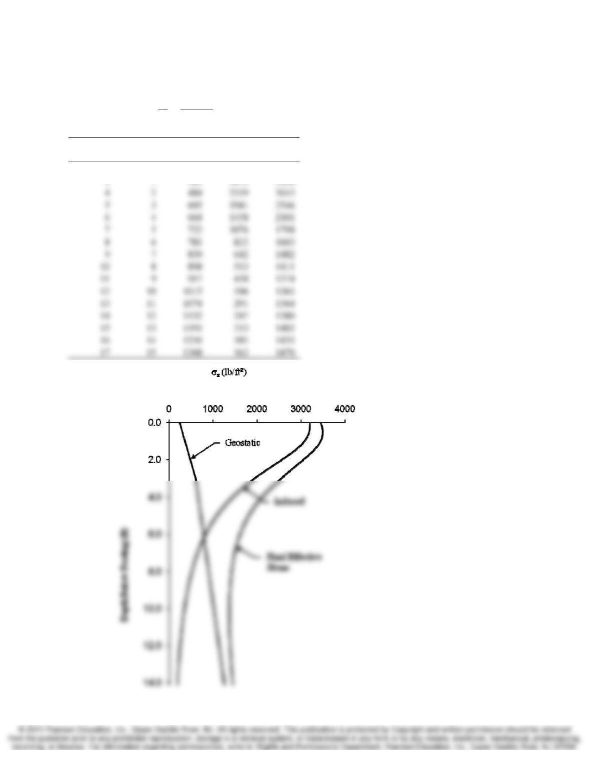
9.32 A proposed 5 ft × 5 ft spread footing foundation will support an office building. The
column load plus the weight of the foundation will be 80 k, and the bottom of the
foundation will be 2 ft below the ground surface. The unit weight of the soil is 121 lb/ft3
and the groundwater table is at a depth of 5 feet. Develop a plot of the vertical effective
stress below the center of this foundation versus depth (after the footing has been placed
and loaded). Consider depths from the bottom of the footing to 15 ft below the bottom of
the footing.
9-30 Stress Chap. 9
Solution
2
2
lb/ft 3200
5
000,80 === A
P
q
z (ft) z
f
(ft)
σ‘
z0
(lb/ft
2
)
Δσ
z
(lb/ft
2
)
σ
‘
z
(lb/ft
2
)
2 0 242 3200 3442
Chap. 9 Stress 8-31
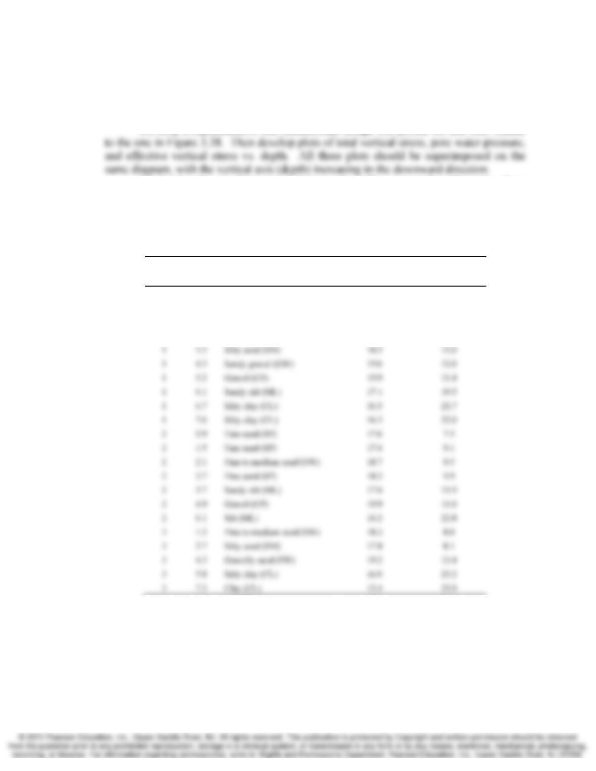
9.33 The data in the following table were obtained from three borings at a certain site. The
ground surface is level, and the groundwater table is at a depth of 3.7 m below the ground
surface.
Develop a representative one-dimensional design soil profile for this site, similar
To develop the one-dimensional design soil profile, convert the information from
the table into three boring logs. Then compare these logs, looking for similar soil types,
and combine them into a single representative profile. Then use the γd and w values to
compute the average unit weight for each strata. Keep in mind that computations of the
total stress are based on the unit weight, γ, not the dry unit weight, γd.
Boring
Depth
(m)
Soil Classification Dry Unit Weight
(kN/m3)
Moisture Content
(%)
1
0.6
Medium sand (SP) 18.1
8.2
1
1.2
Fine to medium sand (SW) 17.9
8.0
1
2.1
Medium sand (SP) 18.7
8.9
1
2.7
Silty sand (SM) 18.4
10.3
9-32 Stress Chap. 9
Solution
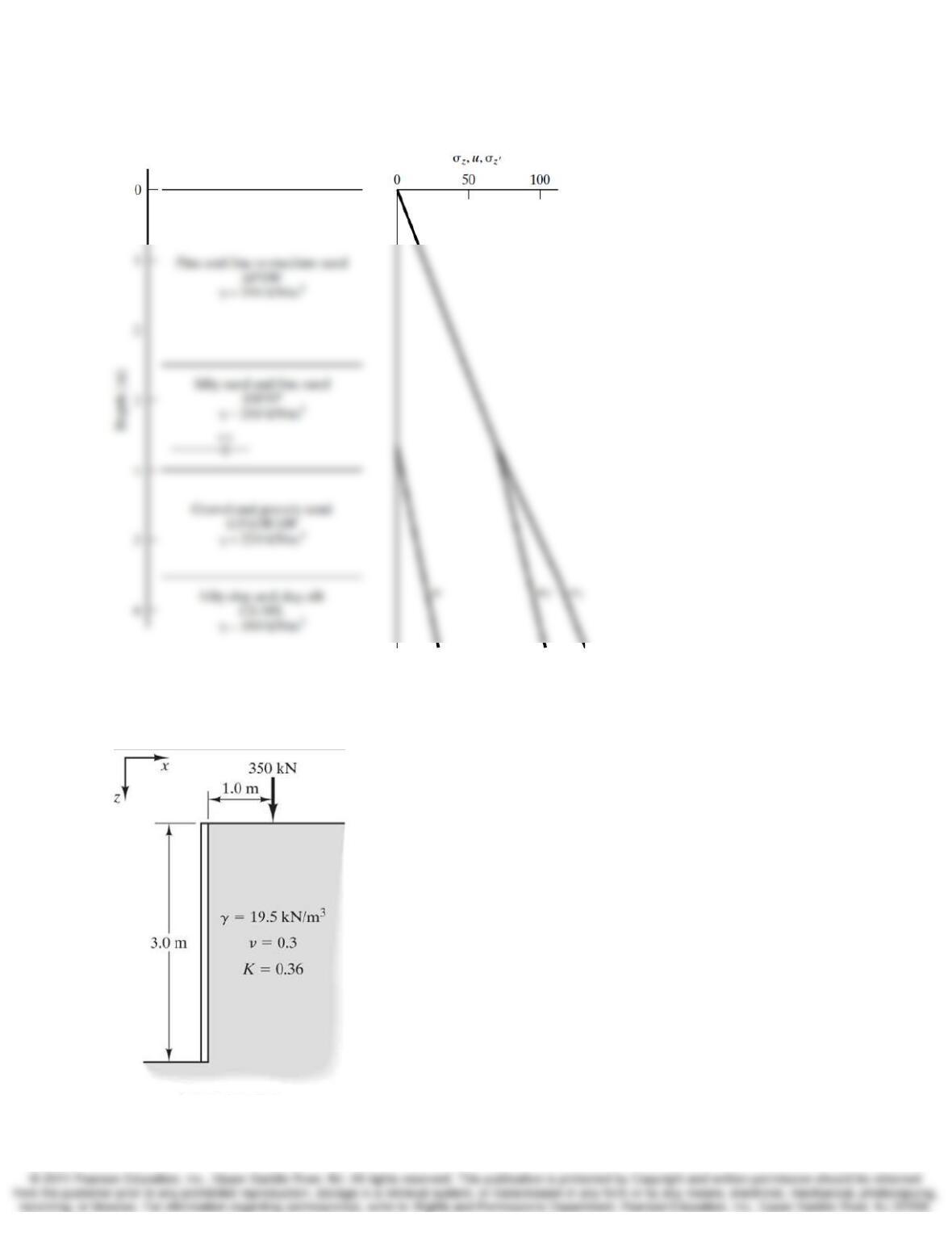
9.34 A point load is to be applied near an existing retaining wall as shown in Figure 9.31.
Develop plots of the geostatic and induced horizontal contact pressure, σx, acting on the
wall at the following immediately adjacent to the point load.
Figure 9.31 Cross section of retaining wall for Problem 9.34.
Chap. 9 Stress 8-33
Solution
The effective geostatic horizontal stress, σ´x0, is computed as
The induce horizontal stress, Δσx, is computed using Equation 9.24 with
Using the above information and the spreadsheet Stress_Distribution.xlsx to compute Δσx,
we can compute the following values.
z (ft)
σz0
(lb/ft2)
σx0
(lb/ft2)
Δ
σx
(lb/ft2)
σ
x
(lb/ft2)
0.00 0.00 0.00 0.00 0.00
0.20 3.90 1.40 12.39 13.79
0.40 7.80 2.81 32.12 34.93
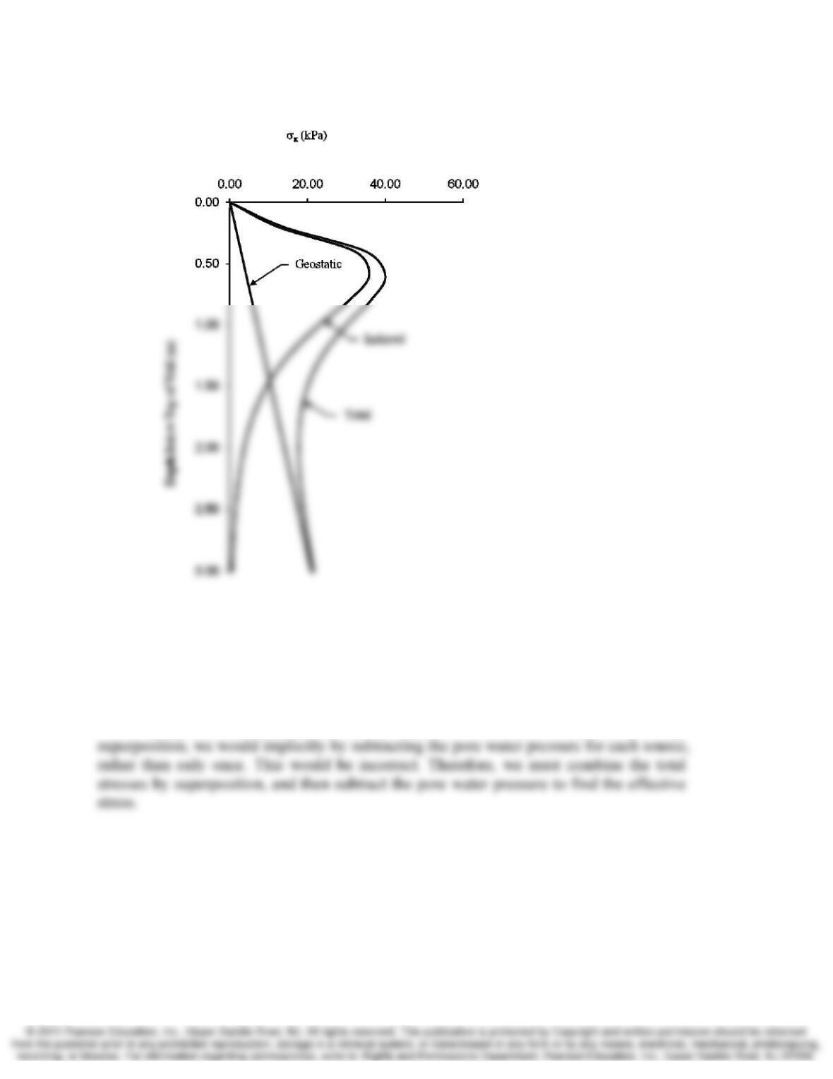
9-34 Stress Chap. 9
Which plot as:
9.35 When combining stresses from multiple sources, Equation 9.35 instructs us to combine
the total stresses using superposition, then subtract the pore water pressure. Why would
it be incorrect to compute the various effective stresses, then combine them by
superposition?
Solution
If we computed the effective stress from each source, then combined them by
9.36 An excavation similar to the one in Figure 8.7 has recently been constructed and
dewatered. Unfortunately, this excavation is beginning to show signs of incipient heave
and/or quicksand problems. An analysis similar to the one in Example 9.8 confirms that
this is a potential problem.
As an emergency measure, the contractor is proposing to remove the dewatering
pumps, and fill the excavation with water. Evaluate this proposal and prepare a 200–300
Chap. 9 Stress 8-35
word essay describing why this method would or would not provide temporary relief
from the heave and quicksand problem.
Solution
According to the discussion in Section 9.9, the vertical effective stress becomes zero
when the upward seepage force exceeds the downward vertical stress due to the effective
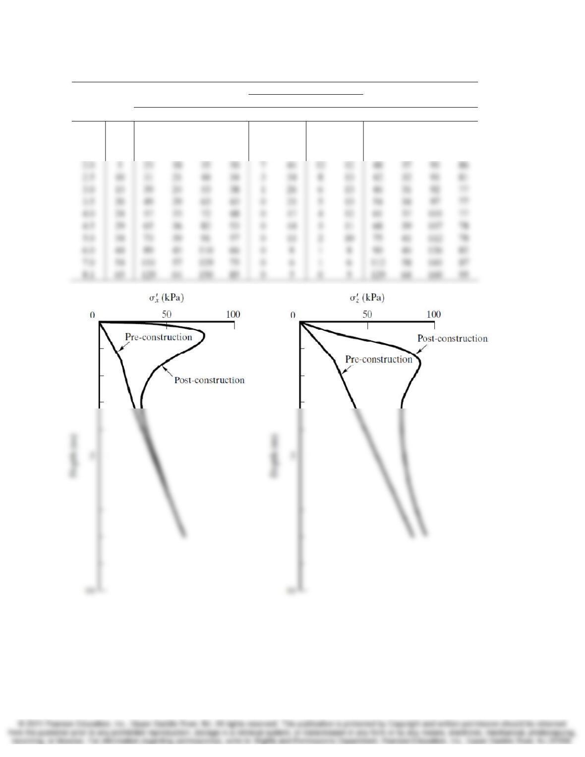
9.37 A point load and a square area load are to be applied to the ground surface as shown in
Figure 9.32. Develop a plot of σz′ versus depth below Point A. This plot should contain
two curves: one that represents the pre-construction condition (i.e., without the applied
loads) and one that represents the post-construction condition. The plot should extend
from the ground surface to the bottom of the fat clay stratum.
Solution
kPa 225
0.2
900
2=== A
P
q
9-36 Stress Chap. 9
Depth
(m) u
Pre-Construction
Induced Stresses
Post-Construction
Point Area
σx σ‘x σ
z σ‘z Δσx Δσz Δσx Δσz σ
x σ‘x σ
z σ‘z
0.5 0 5 5 9 9 68 22 6 1 79 79 32 32
1.0 0 11 11 17 17 44 55 15 5 70 70 77 77
1.5 0 16 16 26 26 18 55 14 9 70 48 90 90
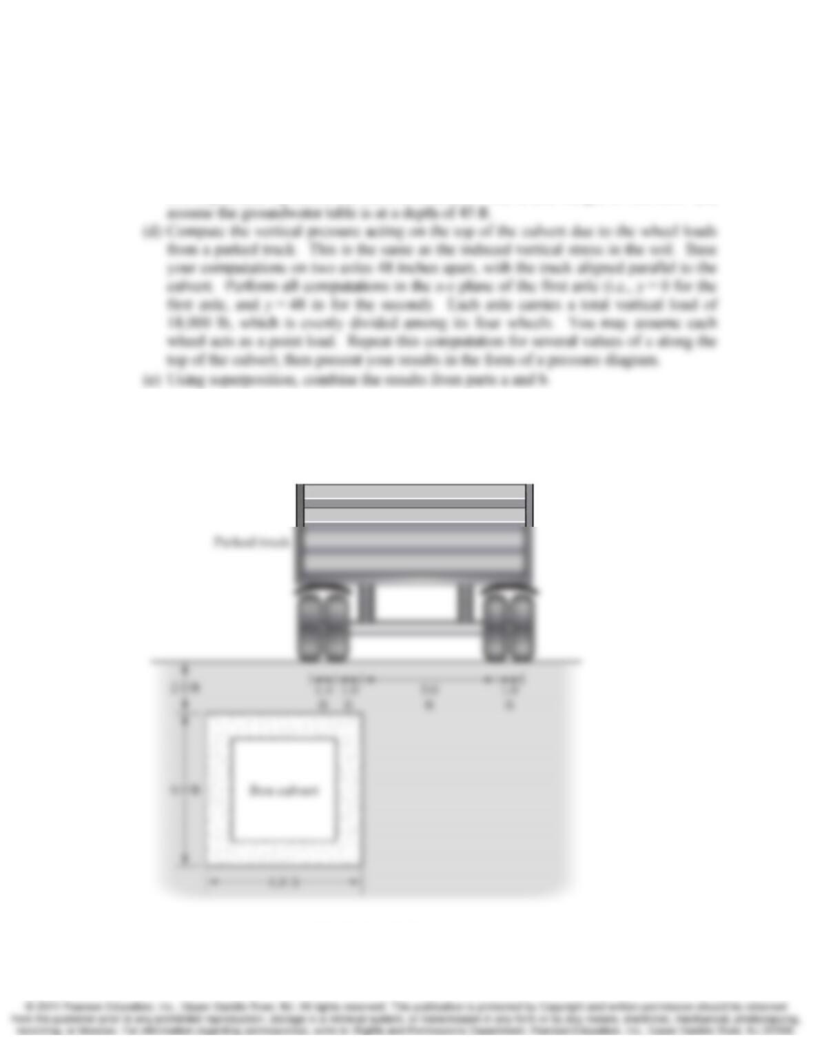
9.38 A truck stop is to be built on a parcel of land adjacent to a major highway. During the
planning stage of this project, the engineers found an existing 6 ft by 6 ft concrete box
culvert under the proposed truck parking area, as shown in Figure 9.33. The project
engineer is concerned that the weight of the parked trucks may overstress it, and has
asked you to compute the vertical pressures acting on the top of the culvert. The results
of your analyses will be provided to a structural engineer, who will then develop shear
Chap. 9 Stress 8-37
and moment diagrams and determine if the culvert can safely support the weight of the
trucks.
(c) Compute the vertical pressure acting on the top of the culvert due to the weight of the
overlying soil without any trucks. This is the same as the geostatic vertical stress at
this depth, and represents the current condition. Use a unit weight of 120 lb/ft3 and
Note: The culvert is stiffer than the soil, so the Boussinesq solution gives an approximate
solution to this problem. A more precise analysis would need to consider the ratio of
modulii of elasticity in the soil and the culvert, and is beyond the scope of this book (see
Poulos and Davis, 1974).
9-38 Stress Chap. 9
Solution
4
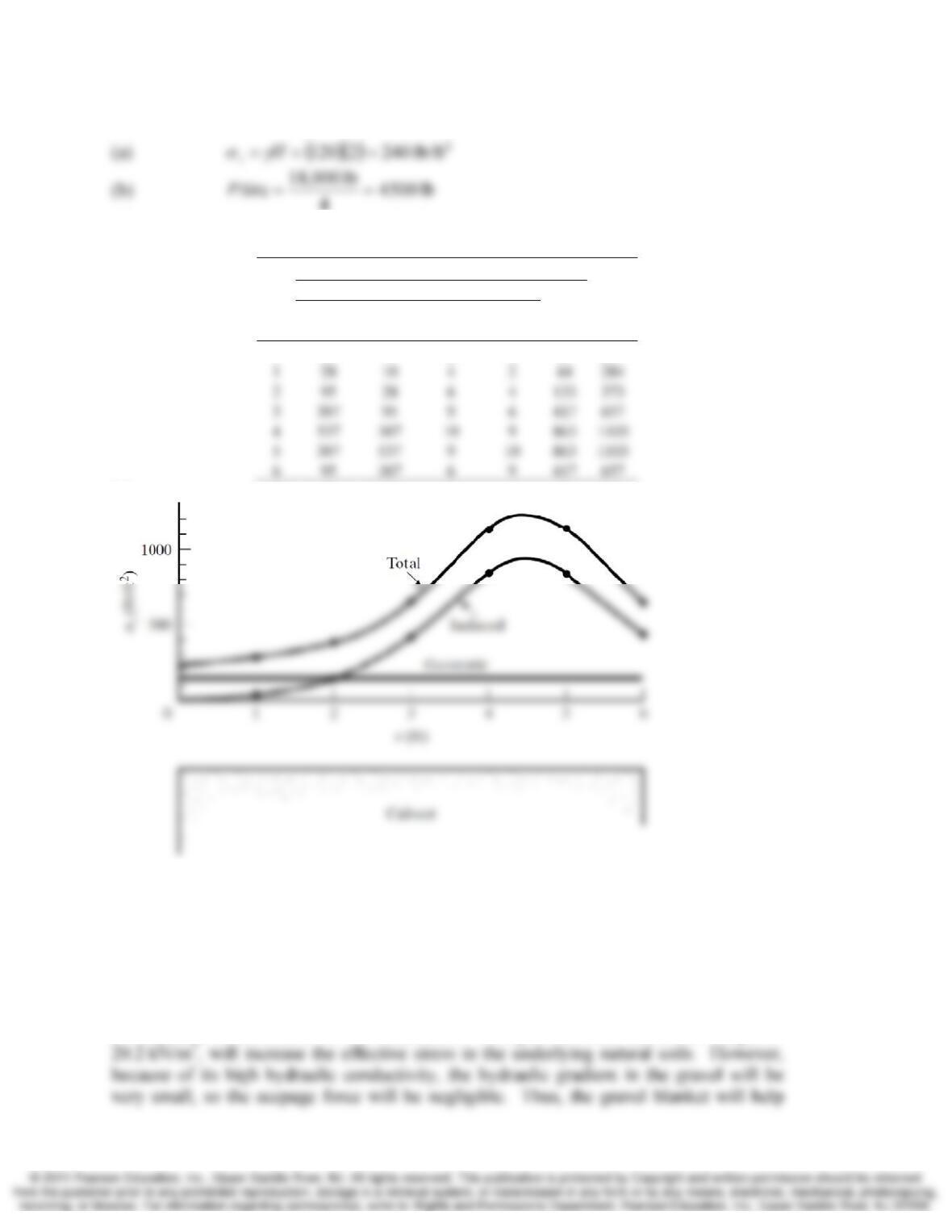
The induced stresses from the right wheels are small and will be neglected.
x
(ft)
σz
,
induced
Total
Rear Axle Front Axle
Sum
Outside
wheel
Inside
Wheel
Outside
wheel
Inside
Wheel
0 10 4 2 1 17 257
(c)
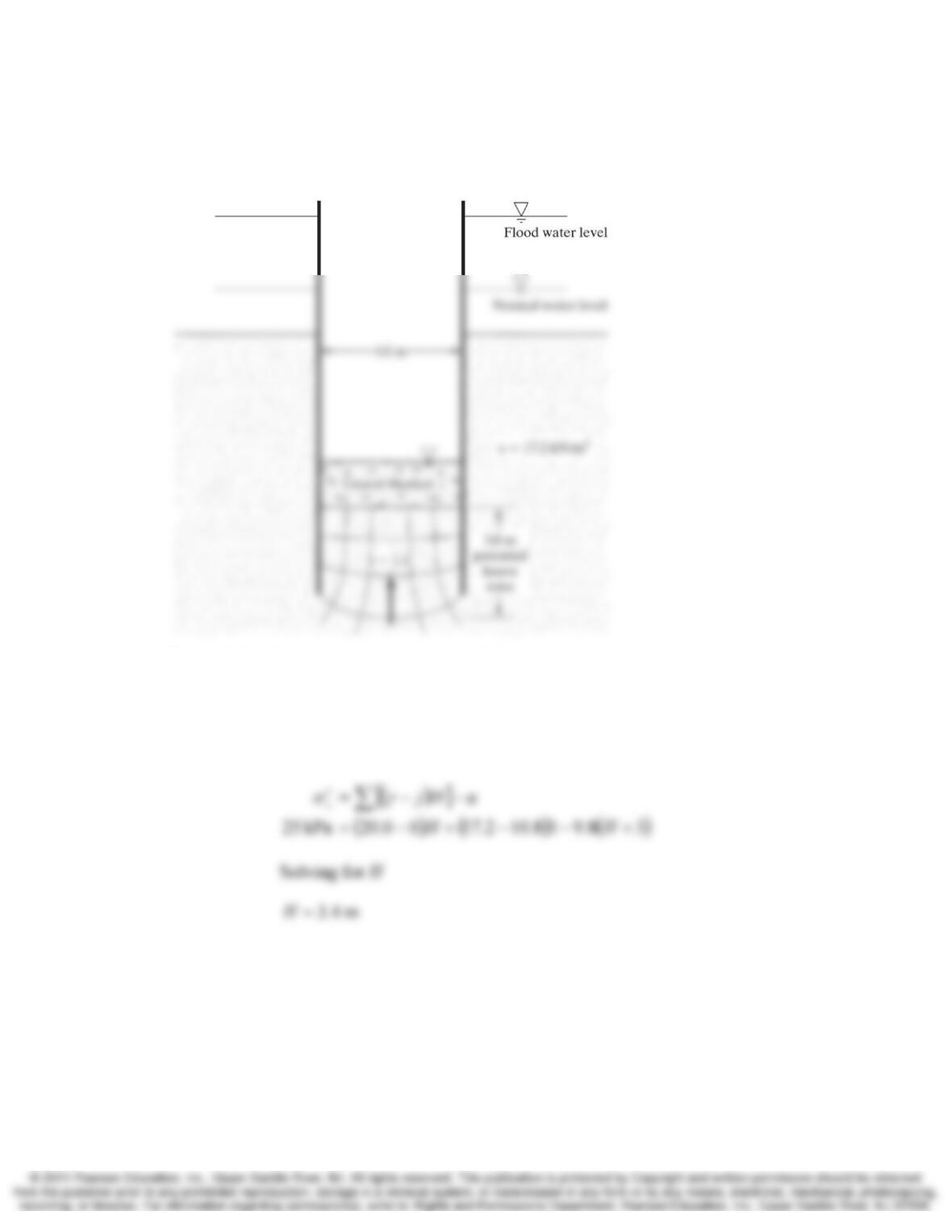
9.39 The excavation shown in Figure 9.34 is to be made in a river. When the normal water
level is present in the river, the hydraulic gradient at the bottom of the excavation is low
enough to provide a sufficient margin of safety against heaving and quicksand. However,
if the river rises to the design flood level, the hydraulic gradient will increase to 1.1,
which will probably cause problems.
To provide sufficient protection against heave and quicksand, a gravel blanket is
to be placed in the bottom of the excavation. This gravel, which has a unit weight of
Chap. 9 Stress 8-39
protect the excavation against heave. The design requires a vertical effective stress of at
least 25 kPa in the upper 3 m of soil. Determine the minimum required thickness of the
gravel blanket.
Figure 9.34 Cross-section for Problem 9.39
Solution
()
(
)
3
kN/m 10.88.91.1 === w
ij
γ