9-1
CHAPTER 9
Stress
QUESTIONS AND PRACTICE PROBLEMS
Section 9.1 Mechanics of Materials
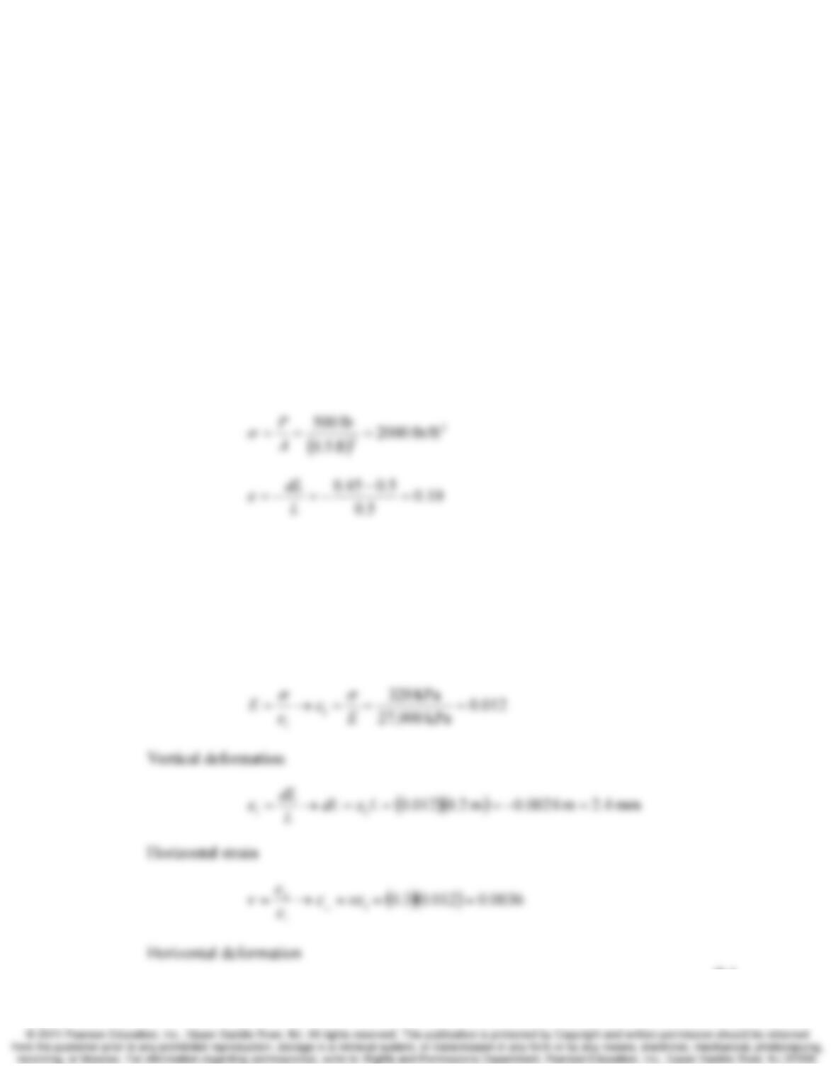
9.1 A 0.500 ft × 0.500 ft × 0.500 ft cube of soil is subjected to a vertical compressive force of
500 lb. This force is being applied to the top of the cube. As a result of this force, the
cube compresses to a height of 0.450 ft. Compute the vertical normal stress, the vertical
normal strain, and the Young’s modulus of the soil.
Solution
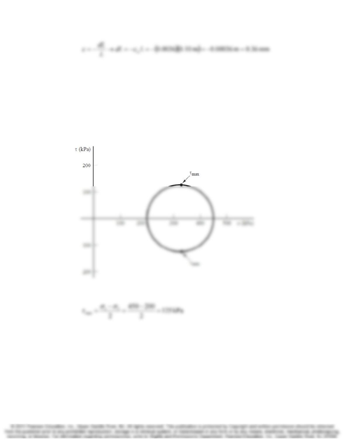
9.2 A soil has a Young’s modulus of 27,000 kPa and a Poisson’s ratio of 0.3. A cylindrical
sample of the soil 0.10 m in diameter and 0.2 m tall is subject to a vertical stress of
320 kPa. Compute the vertical normal strain, vertical deformation, horizontal normal
strain and horizontal deformation.
Solution
Vertical normal strain
9-2 Stress Chap. 9
Section 9.2 Mohr Circle Analyses
9.3 The major and minor principal stresses at a certain point in the ground are 450 and
200 kPa, respectively. Draw the Mohr circle for this point, compute the maximum shear
stress, τmax, and indicate the points on the Mohr circle that represent the planes on which
τmax acts.
Solution
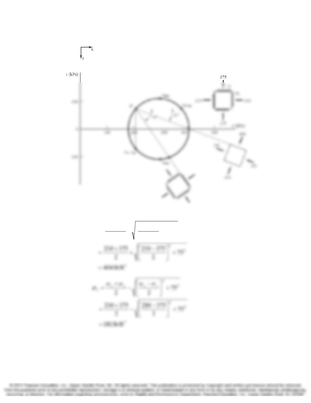
9.4 The stresses at a certain point in the ground are σx = 210 kPa, σz = 375 kPa, τzx = 75 kPa
and τxz = – 75 kPa. Draw the Mohr circle for this point and determine the following:
(a) The point pole
(b) The mean normal and deviator stress
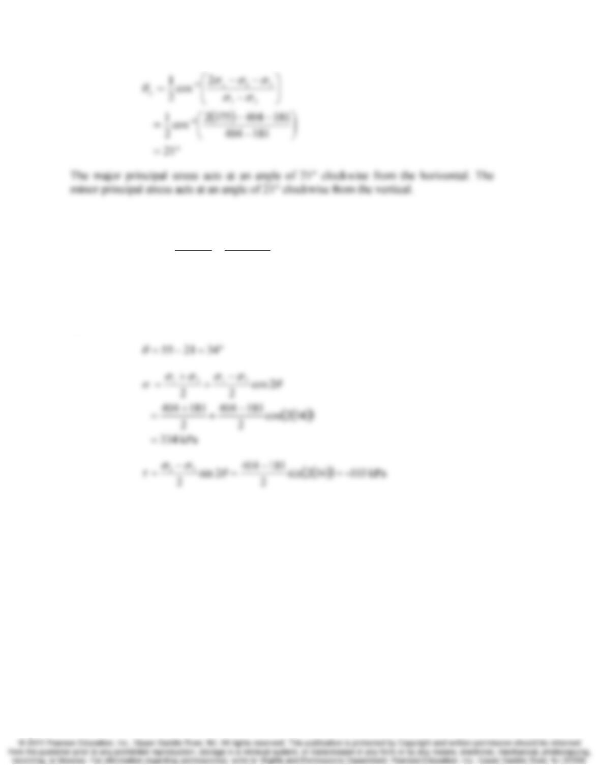
(c) The magnitudes and directions of the principal stresses.
(d) The magnitude and directions of the maximum shear stress.
(e) The normal and shear stresses acting on a plane inclined 55° clockwise from the
horizontal.
Chap. 9 Stress 8-3
Solution
(a)
2
2
1
22
+
⎥
⎦
⎤
⎢
⎣
⎡−
+
+
=zx
zxzx
τ
σσσσ
σ
9-4 Stress Chap. 9
(b)
kPa 111
2
181404
2
31
max =
−
=
−
=
σ
σ
τ
The maximum shear stress acts at an angle of 21 + 45 = 66° clockwise and 21 – 45 = 24°
counterclockwise from the horizontal.
(c)
σ
σ
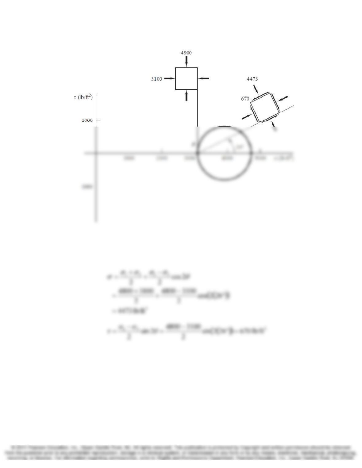
9.5 The major principal stress at a certain point is 4800 lb/ft2 and acts vertically. The minor
principal stress is 3100 lb/ft2. Draw the Mohr circle for this point, locate the pole, then
compute the normal and shear stresses acting on a plane inclined 26° counter-clockwise
from the horizontal.
Solution
Chap. 9 Stress 8-5
Since the major principal stress acts vertically (σ1 = σz), the angle θz=0.
°= 26
θ
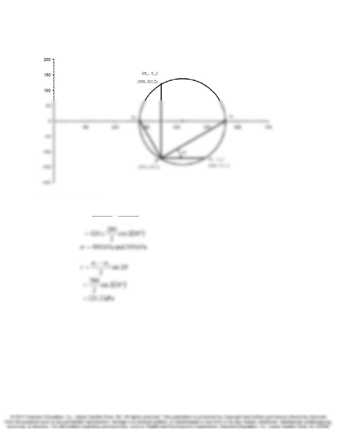
9.6 A certain element of soil is subject to a mean normal stress of 420 kPa and a deviator
stress of 280 kPa. The major principal plane is rotated 30 degrees counterclockwise from
horizontal. Draw the Mohr circle for this soils element, locate the pole, and compute the
normal and shear forces acting on horizontal and vertical planes.
9-6 Stress Chap. 9
Solution
Mohr Circle
Computational solution
2cos
22
3131
−
±
+
=
θ
σ
σ
σ
σ
σ
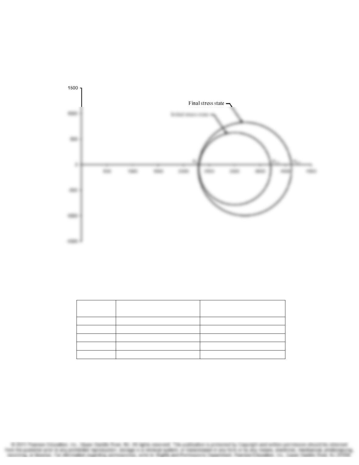
9.7 A laboratory soil sample is initially subject to principal stresses of 3,700 lb/ft2 and 2,300
lb/ft2. During testing, the major principal stress is increased while the minor principal
stress is kept the same. What is the major principle stress when the sample has reached a
deviator stress of 1,800 lb/ft2? Draw the Mohr circles for the two stress conditions on a
single figure.
Chap. 9 Stress 8-7
Solution
2
32,1 lb/ft 4,100800,1300,2 =+=+= d
σσσ
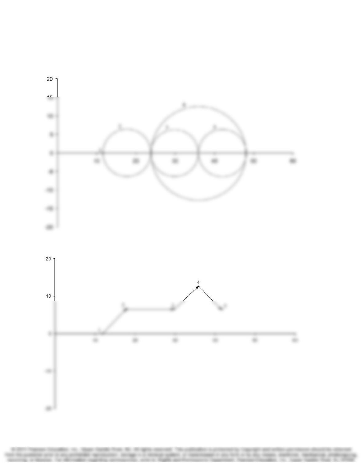
9.8 A cylindrical sample of soil is placed in a special testing device which applies vertical
and horizontal normal stresses to the sample. No shear stresses are applied on the vertical
and horizontal planes so they are always principal planes. The following loading
sequence is applied:
Load Step Vertical Normal Stress
σz (lb/in2)
Horizontal Normal Stress
σx (lb/in2)
1 12 12
2 24 12
3 36 24
4 48 24
5 48 36
Plot the stress path followed during this load sequence. Create two separate plots, one
showing the stress path using Mohr circles and a separate plot showing the stress path in
p-q space.
9-8 Stress Chap. 9
Solution
Mohr circle:
In p-q space:
Chap. 9 Stress 8-9
Sections 9.5 and 9.6 Geostatic and Induced Stresses
9.9 A certain sandy soil has a total unit weight of 118 lb/ft3. What is the vertical normal
stress, σz, at a point in this 15 ft below the ground surface?
Solution
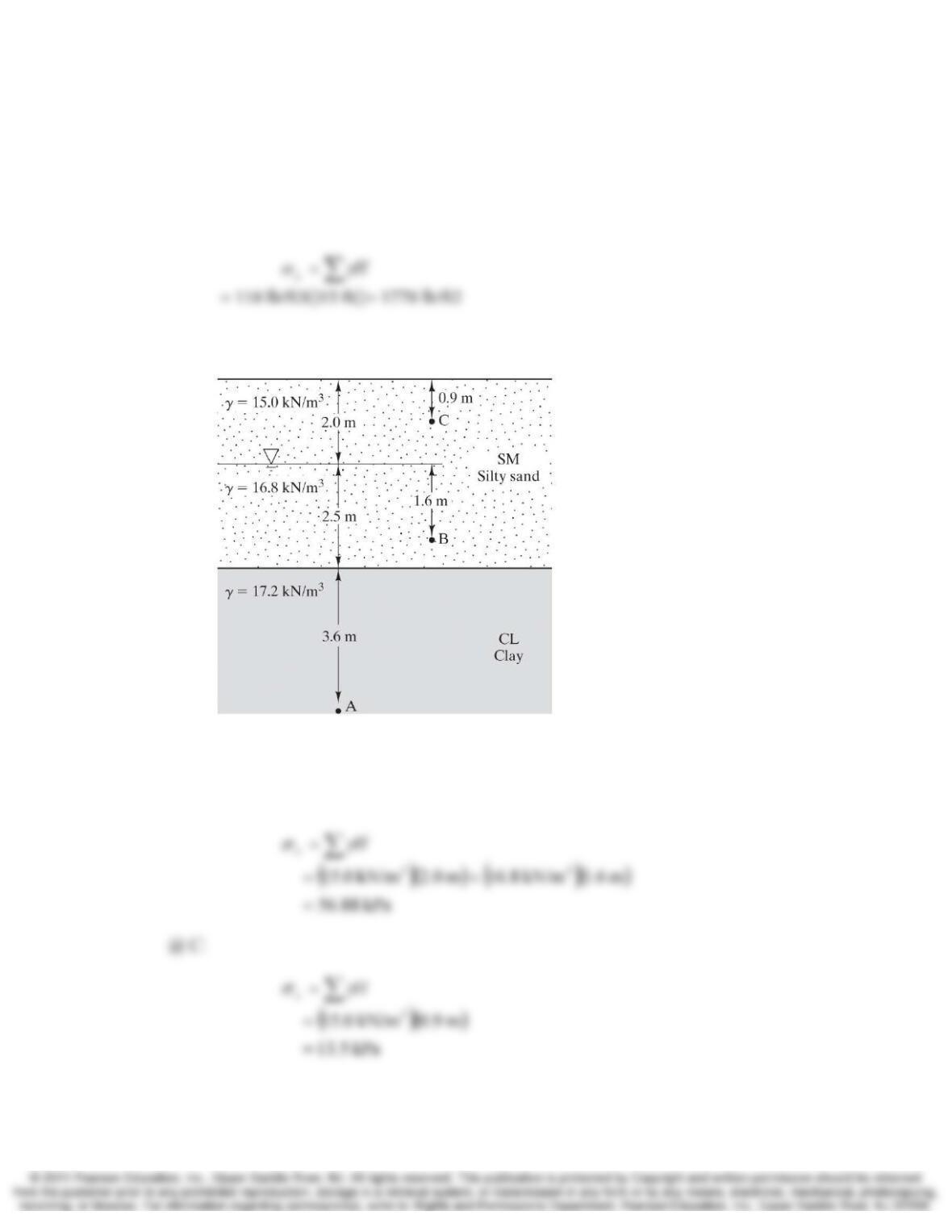
9.10 Compute the vertical normal stress, σz, at points A, B, and C in Figure 9.11.
Figure 9.11 Soil profile for Example 9.2.
Solution
@ B:
9-10 Stress Chap. 9
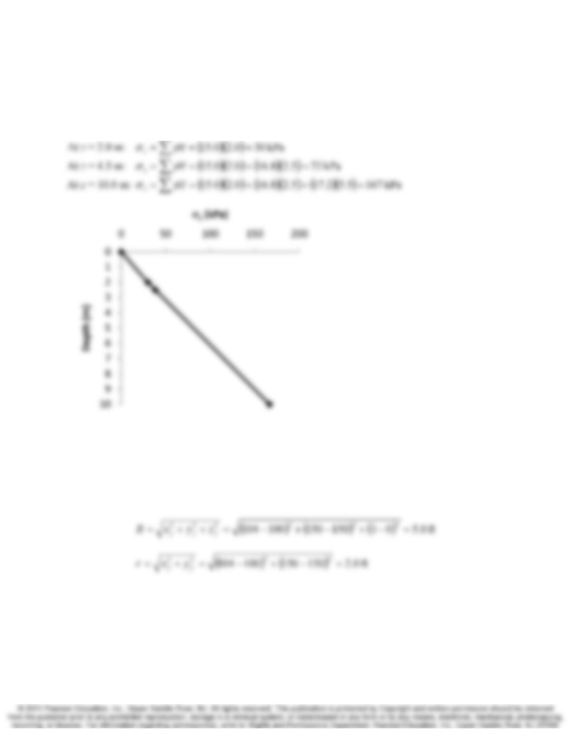
9.11 Using the soil profile in Figure 9.11, develop a plot of σ
z
versus depth. Consider depths
between 0 and 10 m.
Solution
At z = 0:
∑
== 0H
z
γσ
9.12 A vertical point load of 50.0 k acts upon the ground surface at coordinates x = 100 ft,
y = 150 ft. Using a Poisson’s ratio of 0.40, compute the induced stresses Δσ
x
, Δσ
z
, and
Δτ
xz
at a point 3 ft below the ground surface at x = 104 ft, y = 150 ft.
Solution
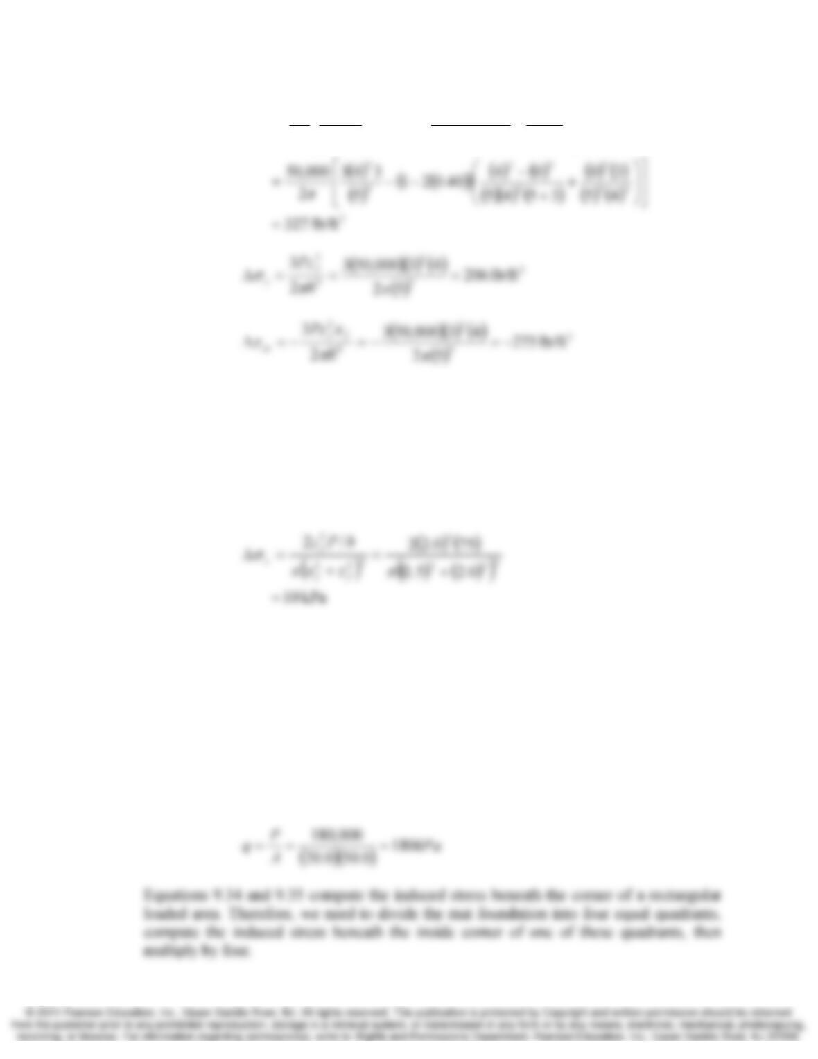
Using Equation 9.23—9.30:
Chap. 9 Stress 8-11
()
()
23
2
2
22
5
2
21
3
2
⎥
⎥
⎦
⎤
⎢
⎢
⎣
⎡
⎟
⎟
⎠
⎞
⎜
⎜
⎝
⎛+
+
−
−−=Δ
ν
π
σ
rR
zy
zRRr
xy
R
zx
Pff
f
ffff
x
9.13 A vertical line load of 75 kN/m acts upon the ground surface. Assuming this load
extends for a very long distance in both directions, compute the induced vertical stress,
Δσz, at a point 1.5 m horizontal (measured perpendicular to the line) and 2.0 m below the
line.
Solution
Using Equations 9.31
9.14 A grain silo is supported on a 20.0 by 50.0 m mat foundation. The total weight of the silo
and the mat is 180,000 kN. Using Boussinesq’s method, compute the induced vertical
stress, Δσz, in the soil at a point 15.0 m below the center of the mat. First use the full
analytical solution given by Equations 9.34 and 9.35. Repeat the computation using the
approximate method given by Equation 9.41. Finally, repeat the computation using
Figure 9.16. Compare the results from these three methods and comment on whether the
differences are significant.
Solution
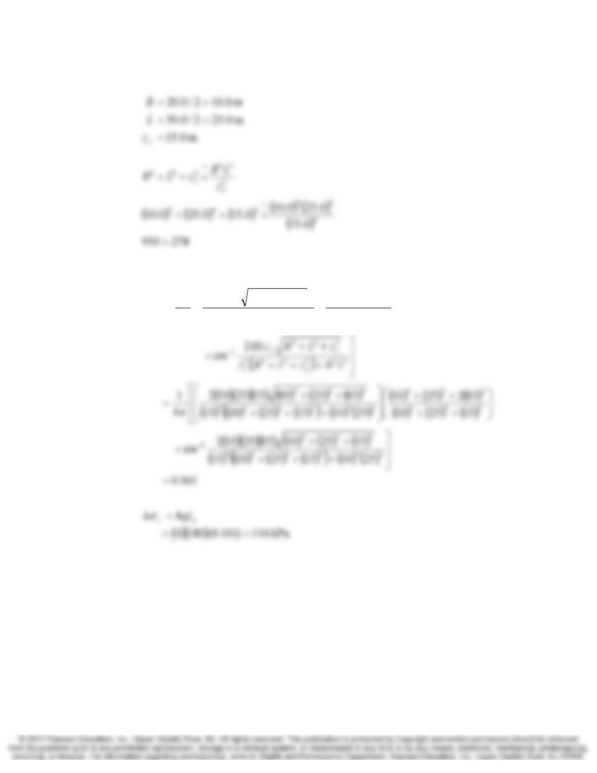
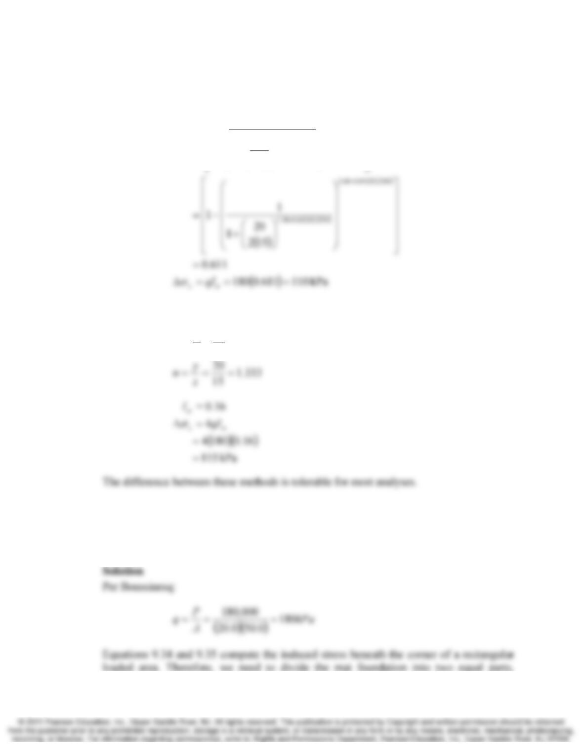
Per Boussinesq:
9-12 Stress Chap. 9
Therefore use Equation 9.35
()
2
2
4
1
222
222
222222
222
⎢
⎢
⎣
⎡
⎟
⎟
⎠
⎞
⎜
⎜
⎝
⎛
++
++
⎟
⎟
⎠
⎞
⎜
⎜
⎝
⎛
+++
++
=
σ
π
zLB
zLB
LBzLBz
zLBBLz
I
f
f
ff
ff
z
Per Equation 9.41
Chap. 9 Stress 8-13
2
1
1
1
/84.060.2
/62.038.1
⎥
⎥
⎥
⎥
⎥
⎥
⎤
⎢
⎢
⎢
⎢
⎢
⎢
⎡
⎟
⎟
⎟
⎟
⎟
⎟
⎠
⎞
⎜
⎜
⎜
⎜
⎜
⎜
⎝
⎛
⎟
⎟
⎠
⎞
⎜
⎜
⎝
⎛
+
−=
−
+
σ
z
B
I
LB
LB
f
Per Figure 9.16
667.0
15
10
===
z
x
m
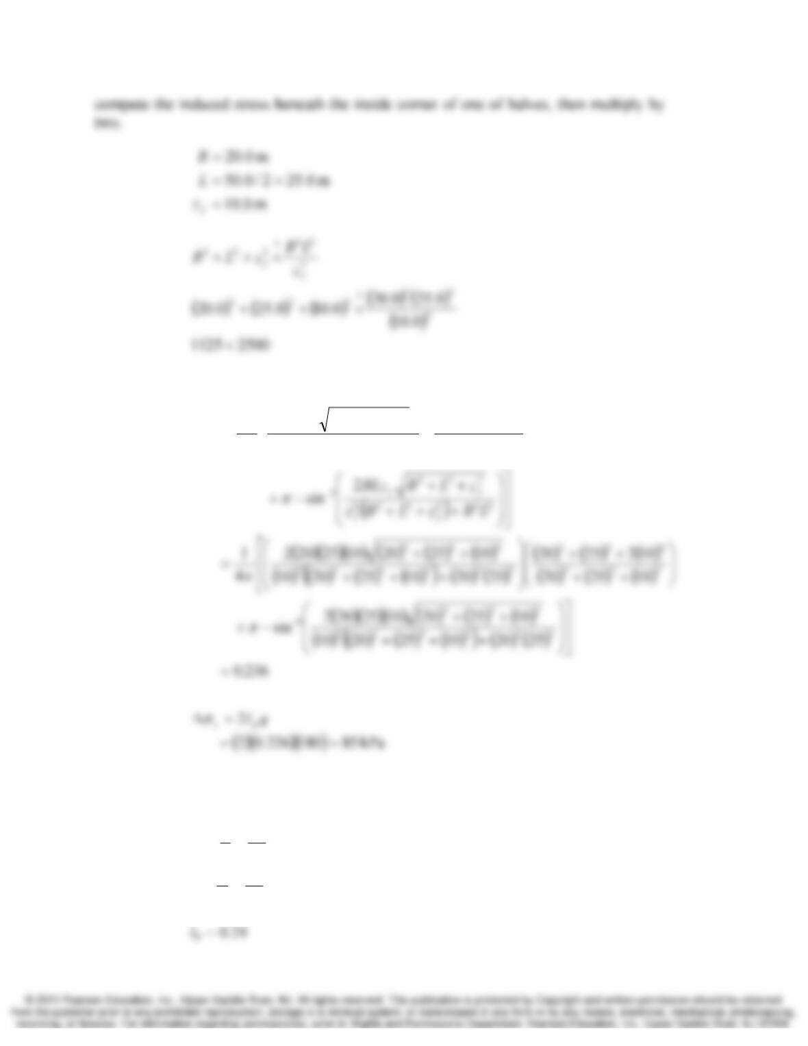
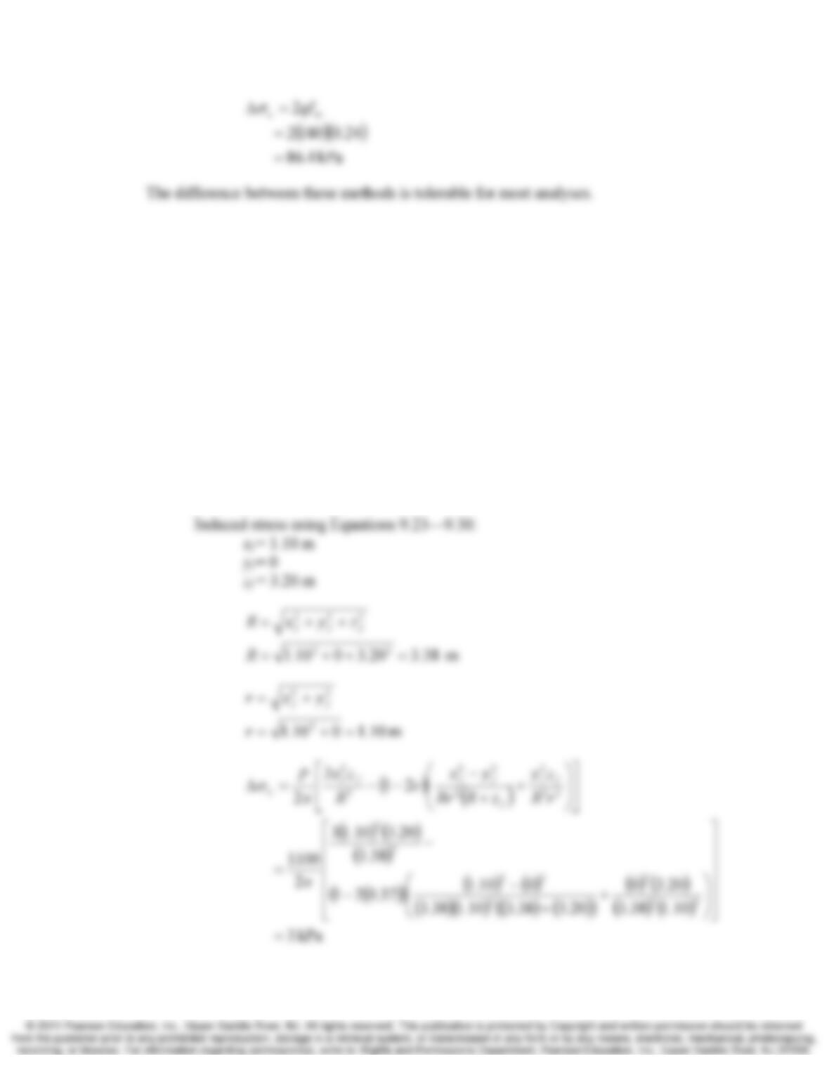
9.15 For the grain silo described in Problem 9.14, compute the induced vertical stress, Δσz, in
the soil at a point at the midpoint of the long edge of the mat and 10 m below the ground
surface. Use both analytical solution given by Equations 9.34 and 9.35 and the chart
method using Figure 9.16 and compare the results.
9-14 Stress Chap. 9
Therefore use Equation 9.35
()
2
2
4
1
222
222
222222
222
⎟
⎟
⎠
⎞
⎜
⎜
⎝
⎛
++
++
⎟
⎟
⎠
⎞
⎜
⎜
⎝
⎛
+++
++
=
zLB
zLB
LBzLBz
zLBBLz
I
f
f
ff
ff
σ
π
Per Figure 9.16
5.2
10
25
2
10
20
===
===
z
y
n
z
x
m
Chap. 9 Stress 8-15
Section 9.7 Superposition
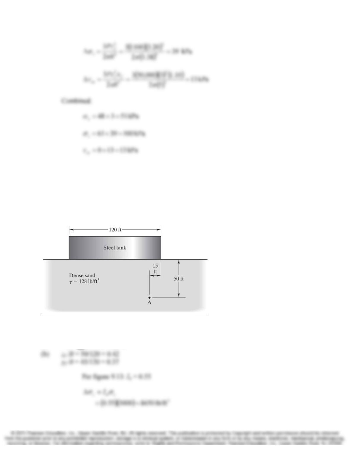
9.16 A dilatometer test (an in-situ test described in Chapter 3) has been conducted at a depth
of 3.20 m in a soil that has a level ground surface and a unit weight of 19.2 kN/m3.
According to this test, the horizontal geostatic σx at this point is 48 kPa. A proposed
vertical point load of 1100 kN is to be applied to the ground surface at a point 1.10 m
west of the test location. Using a Poisson’s ratio of 0.37, compute the total σx, σz, and τzx
at the test point after the load is applied.
Solution
Geostatic:
kPa 48=
x
σ
per dilatometer
(
)
(
)
kPa 612.32.19 ===Δ ∑h
z
γσ
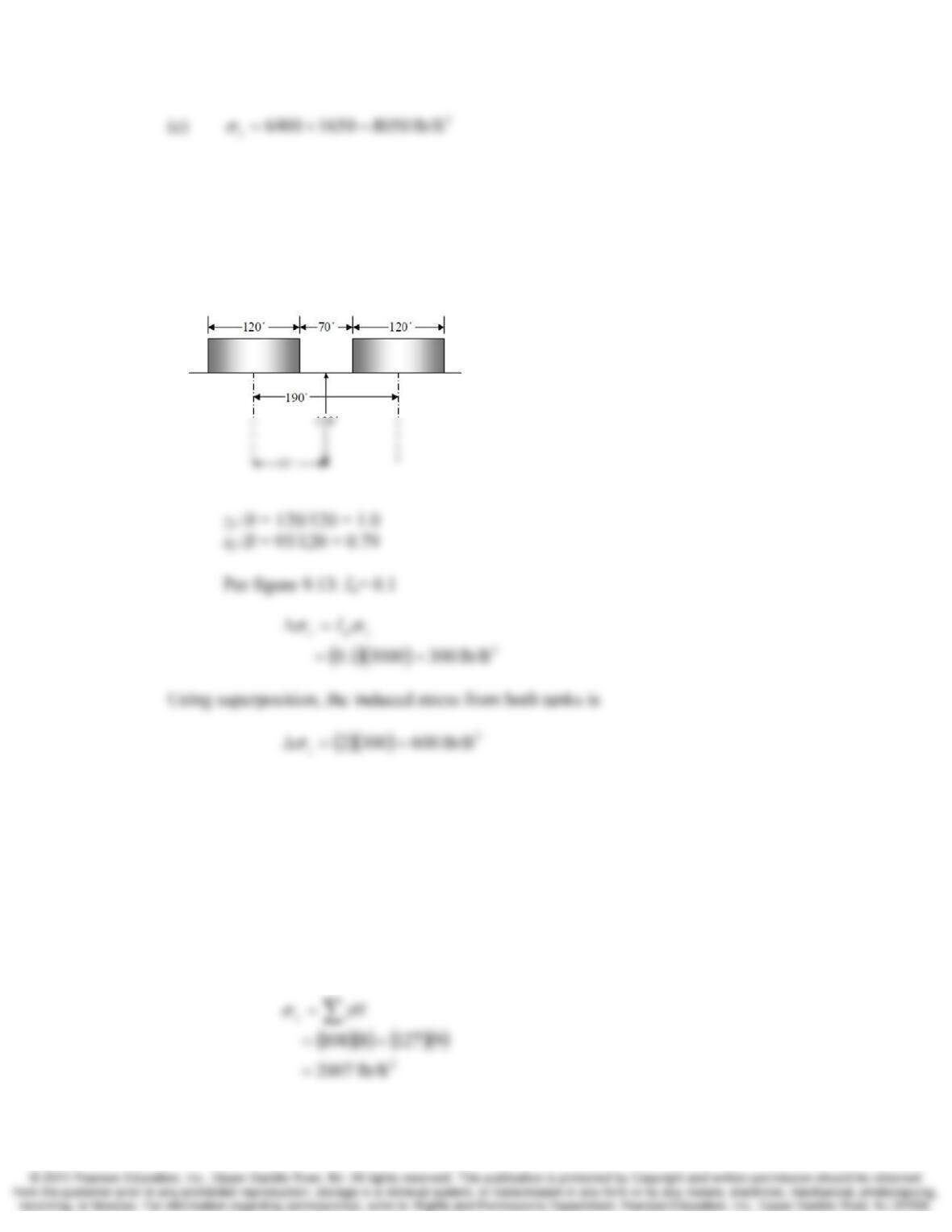
9-16 Stress Chap. 9
9.17 The circular tank in Figure 9.29 imparts a bearing pressure of 3000 lb/ft2 onto the soil
below.
(a) Compute the geostatic vertical stress, σz, at Point A. This is the stress that existed
before the tank was built.
(b) Using Figure 9.13, compute the induced vertical stress, Δσz at Point A due to the
weight of the tank.
(c) Combine the results from a and b to find the total σz at Point A after the tank is built.
Figure 9.29 Storage tank and soil profile for Problem 9.17
Solution
(a)
()()
2
lb/ft 510050128 === ∑H
z
γσ
Chap. 9 Stress 8-17
9.18 A second identical circular tank is constructed to the right of tank in Figure 9.29. The
center to center spacing of the two tanks is 190 ft. Both tanks impart a bearing pressure of
3000 lb/ft2 onto the soil below. Compute the induced vertical stress, Δσz , due to both
tanks at a point midway between the two tanks at a depth of 120 ft.
Solution
Section 9.8 Effective Stresses
9.19 At certain site the soil profile consists of a sandy soil with a total unit weight of 108 lb/ft3
above the water table and 127 lb/ft3 below the water table. The groundwater table is at a
depth of 8 ft. Compute the total vertical stress, σz, and the effective vertical stress, σ‘z, at a
point 17 below the ground surface.
Solution
Total vertical stress:
9-18 Stress Chap. 9
Effective vertical stress:
9.20 A lake with a water depth of 12 m is underlain by a soil with a total unit weight of
18.2 kN/m3. Compute the total vertical stress, σz, and the effective vertical stress, σ‘z, at a
point 8 m below the bottom of the lake.
Solution
Total vertical stress:
kPa 267
.
=
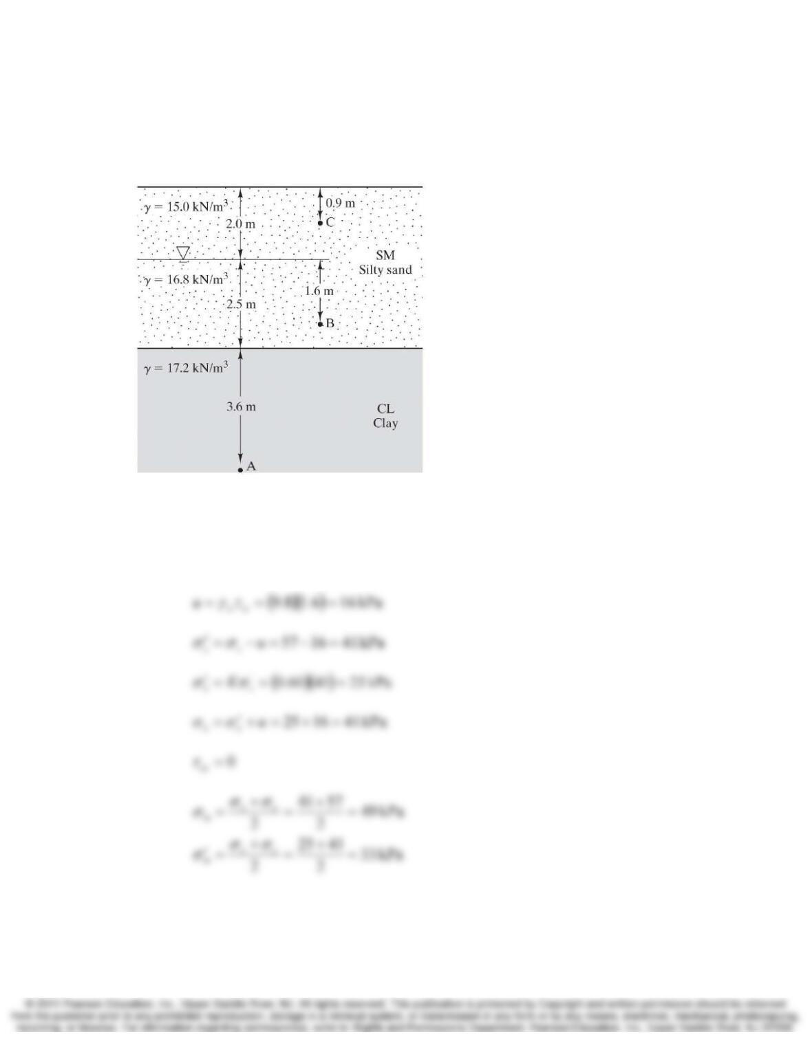
9.21 Develop a plot of σz, u, and σz′ vs. depth for the soil profile in Figure 9.11. Consider
depths from 0 to 10 m, assume hydrostatic conditions are present, and assume u = 0
above the groundwater table. Plot depth, z, on the vertical axis, with zero at the top and
increasing downward. This method of plotting the data is easier to visualize, because
depth on the plot is comparable to depth in a cross-section.
Solution
At z = 0:
Chap. 9 Stress 8-19
At z = 4.5 m:
Since γ is constant between each of these points, the plot of σz between each point is a
straight line. This data plots as shown below.
9-20 Stress Chap. 9
9.22 Compute the values of σx, σx′, σz, σz′, and τzx at Point B in Figure 9.11. The coefficient of
lateral earth pressure in the silty sand is 0.60. Draw both the total and effect stress
Mohr’s circles for Point B on the same figure.
Figure 9.11 Soil profile for Example 9.2.
Solution
()()
(
)
(
)
∑=+== kPa 576.18.160.20.15H
z
γσ