Chap. 9 Spread Footings-Geotechnical Design
9.14 A 3 ft x 7 ft rectangular footing is to be embedded 2 ft into the ground and will support a single
centrally–located column with the following factored LRFD ultimate design loads: PU = 50 k,
VU = 27 k, MU = 80 ft–k. VU and MU act in the long direction only. The underlying soil is a silty
sand with c’ = 0,
φ
’ = 31o, γ = 123 lb/ft3, and a very deep groundwater table. Using LRFD,
determine if this design is acceptable.
Solution
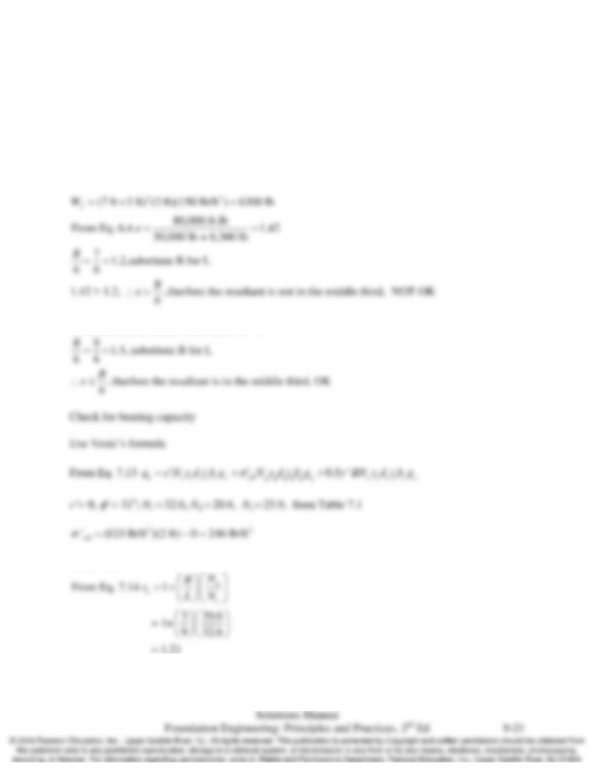
Check for eccentricity
For the criterion to meet increase L to 9 ft
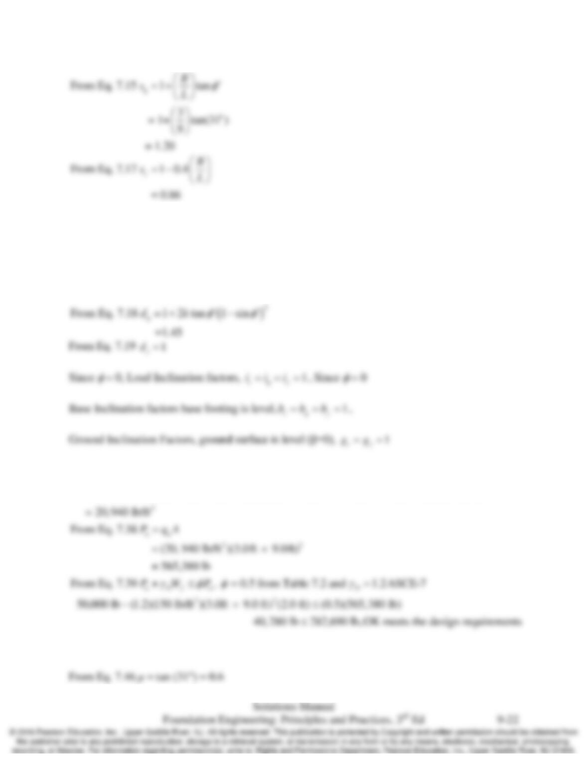
Shape factors
Chap. 9 Spread Footings-Geotechnical Design
Depth Factors
k = D/B
From Eq. 7.17 1 0.4
= 1+0.4(0.6)
= 1.24
c
dk= +
23
0.5 ‘ ), = 0.5 from Table 7.2
=(0)+(246 lb/ft )(20.6)(1.20)(1.45)(1)(1)(1)+0.5(123 lb/ft )(9)(25.9)(0.86)(1)(1)(1)(1)
n c c c c c c zD q q q q q q
q cNsdibg Nsdibg BNsdibg
γ γ γγ γ γ
σ γφ
′
=′+ +
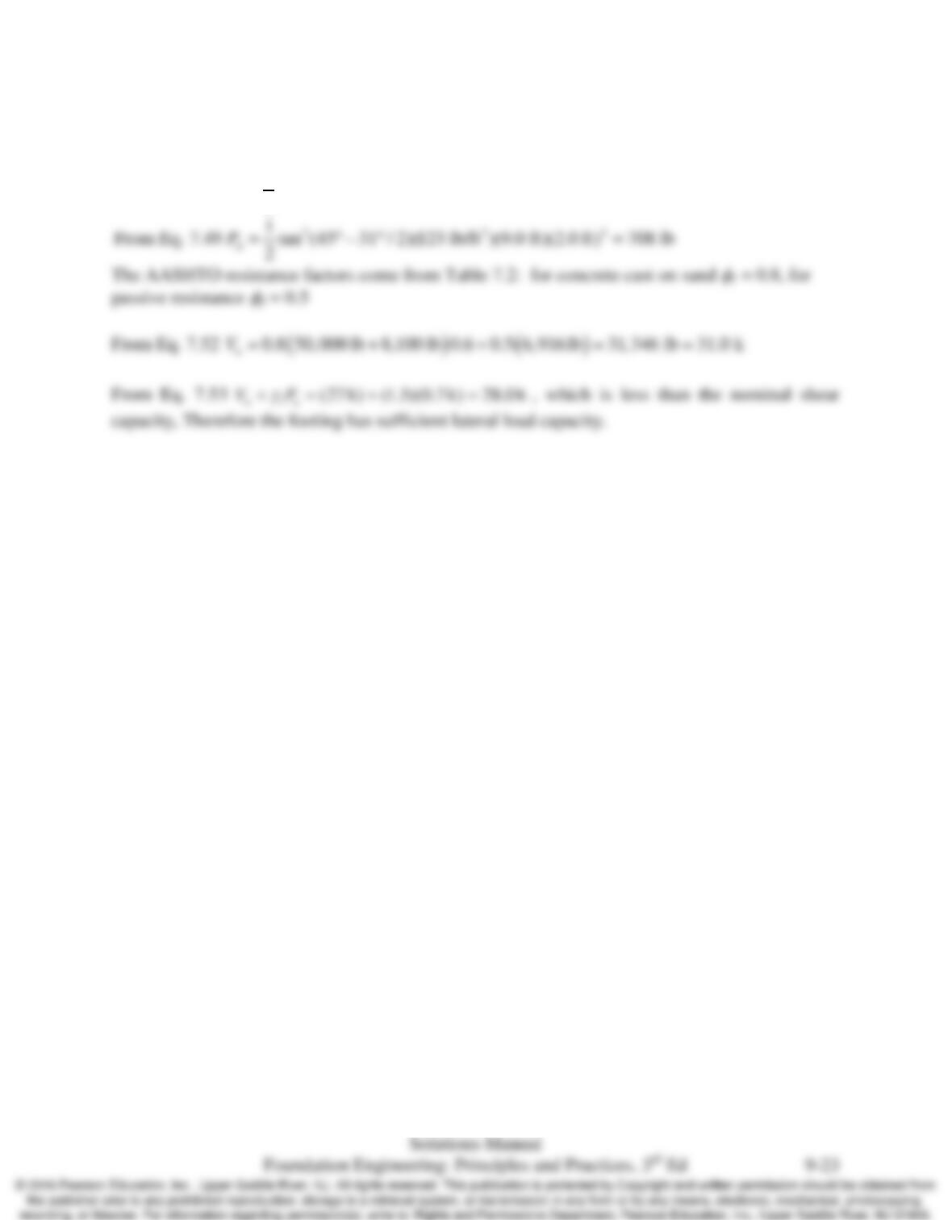
Check for lateral load capacity
Chap. 9 Spread Footings-Geotechnical Design
23
2 32
(3.0 ft 9.0ft) (2.0 ft)(150 lb/ft ) 8,100 lb
1
From Eq. 7.48 tan (45 31 / 2)(123 lb/ft )(9.0 ft)(2.0 ft) 6,916 lb
2
f
P
W
P
=×=
= °+ ° =
Chap. 9 Spread Footings-Geotechnical Design
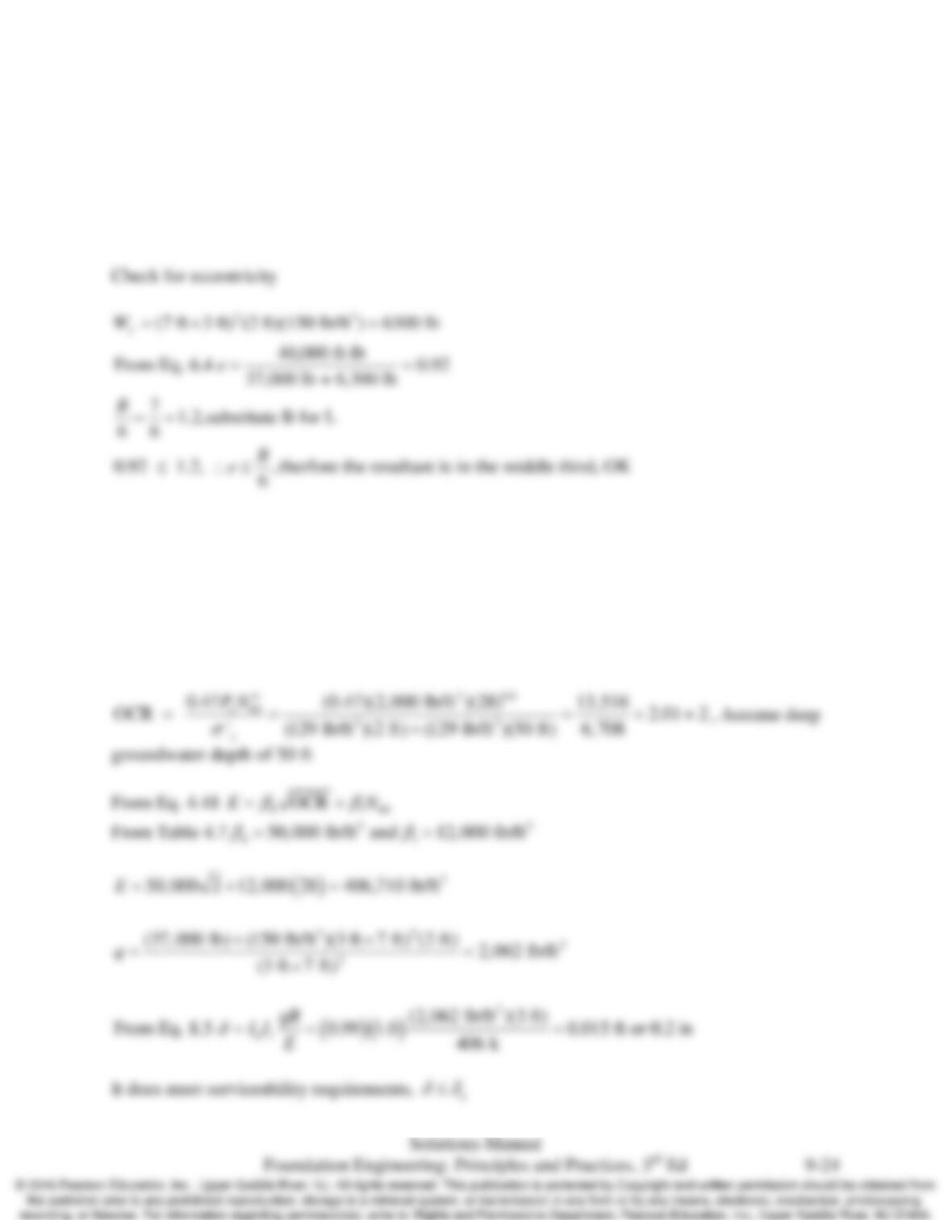
9.15 The serviceability loads for the footing in problem 9.14 are P = 37 k, MU = 40 ft–k, and VU = 0.
The average N60 for the sand below the footing is 28. Determine if this footing meets
serviceability requirements.
Solution
Allowable settlement,
δ
a = 0.75 in
Determine the influence factors, Io and I1
Io= Df/B = 2/3 = 0.6. From Figure 8.2, Io = 0.99
Zh/B =50/3 = 16.7. From Figure 8.2, I1 = 1.0
From Eq. 4.29
Chap. 9 Spread Footings-Geotechnical Design
9.16 A combined footing is to be used to support columns A and B with a center to center spacing of
15 ft. The columns carry the following loads:
The underlying soil is a well-graded sand with c’ = 0,
φ
’ = 36o, γ = 126 lb/ft3, with a very deep
groundwater table. Using LRFD, design a rectangular footing to meet the ultimate limit states.
Assuming the average CPT tip resistance of the sand is 300 kg/cm2, check to see if your design
meets serviceability limits. Adjust the design as needed
Solution
By combining the two isolated footings into a single footing, the eccentric loading can be
eliminated and the bearing pressure be made uniform.
ULS
Estimated depth of footing of Df = 2 ft from Table 9.1
Column A Column B
P V P V
Ultimate loads 200 50 400 50
Service Loads 150 0 300 0
Chap. 9 Spread Footings-Geotechnical Design
Shape factors
Depth Factors
k = D/B, 2/5 = 0.4
Chap. 9 Spread Footings-Geotechnical Design
SLS
Allowable settlement,
δ
a = 0.75 in
t = 50 yr
32
32
(126 lb/ft )(2 ft) 252 lb/ft
(at ) (126 lb/ft )(2 ft 5 ft) 0 882 lb/ft
zD
zp
z DB Hu
σ
σγ
′= =
′= + = −= + −=
∑
Chap. 9 Spread Footings-Geotechnical Design
Layer
No.
Es
(lb/ft2)
zf
(ft)
Iε
Eqs. 8.16
H
(ft)
Iε H/Es
1
1,865,761
0.5
0.234
1
1.26 ×10⁻⁷
2
1,865,761
1.5
0.437
1
1.92 ×10⁻⁷
2
122
252 lb/ft
From Eq. 8.18 1 0.5 1 0.5 0.972
4,800 lb/ft 252 lb/ft
zD
zD
Cq
σ
σ
′
=−=− =
′
−−
Say
δ
= 1/2 in, meets serviceability requirements
Therefore, B x L = 5 ft x 20 ft meets both bearing and serviceability requirements.
3
1,865,761
0.625
2
4
1,865,761
0.566
2
7.79 ×10⁻⁷
5
1,865,761
0.404
2
6.75 ×10⁻⁷
6
1,865,761
0.242
2
7
1,865,761
0.145
2
4.67 ×10⁻⁷
8
1,865,761
0.113
2
3.63 ×10⁻⁷
9
1,865,761
15.5
0.073
3
3.50 ×10⁻⁷
1,865,761
18.5
0.024
3
1.17 ×10⁻⁷
4.19 ×10⁻⁶
Chap. 9 Spread Footings-Geotechnical Design
9.17 A three–story wood-frame building is to be built on a site underlain by sandy clay. This building
will have wall loads of 1900 lb/ft on a certain exterior wall. Using the minimum dimensions
presented in Table 9.3 and presumptive bearing pressures from the International Building Code
as presented in Table 6.1, compute the required width and depth of this footing. Show your final
design in a sketch.
Solution
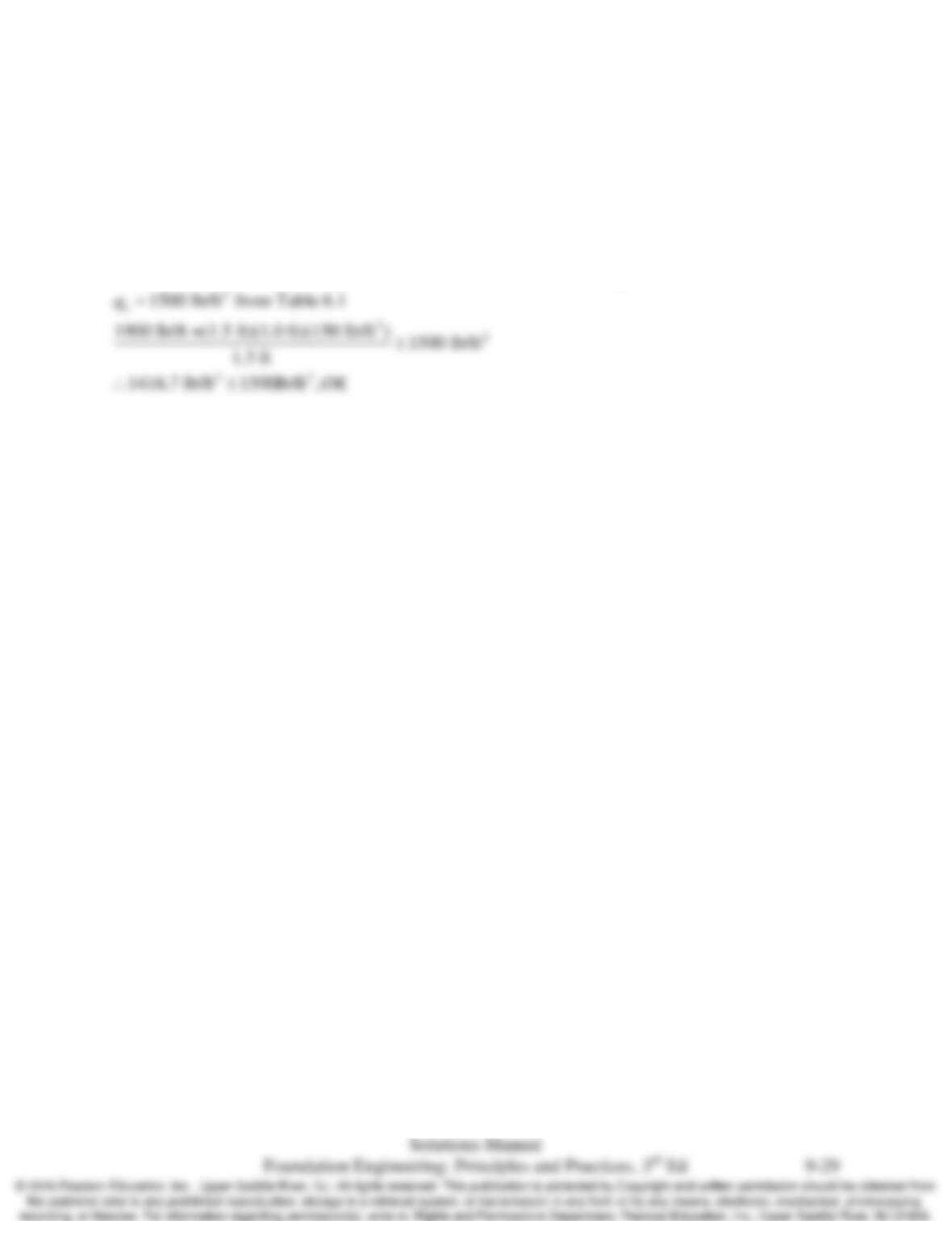
Estimated depth of footing of 1.0ft and width of the footing of 1.5ft from Table 9.3
Chap. 9 Spread Footings-Geotechnical Design
9.18 A 4 ft square, 2 ft deep spread footing carries an ASD design column load of 50 k. The edge of
this footing is 1 ft behind the top of a 40 ft tall, 2H:1V descending slope. The soil has the
following properties: cʹ = 200 lb/ft2,
φ
ʹ = 31, γ = 121 lb/ft3, and the groundwater table is at a
great depth. Compute the ASD factor of safety against a bearing capacity failure and comment
on this design.
Solution
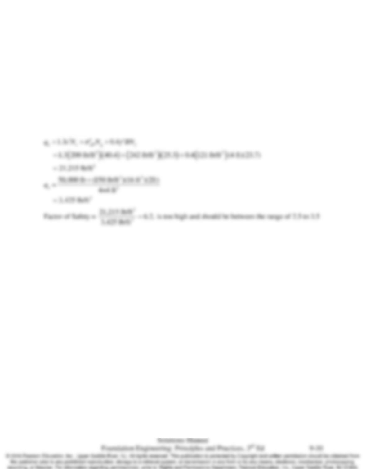
c′= 0,
φ
′= 31o: Nc= 40.4, Nq= 25.3, Nγ= 23.7, from Table 7.1
( )
( )
3
2
121 lb/ft 2 ft
= 242 lb/ft
zD
σ
′=
Chap. 9 Spread Footings-Geotechnical Design
9.19 A Classify the frost susceptibility of the following soils:
e) Sandy gravel (GW) with 3% finer than 0.02 mm.
f) Well graded sand (SW) with 4% finer than 0.02 mm.
g) Silty sand (SM) with 20% finer than 0.02 mm.
h) Fine silty sand (SM) with 35% finer than 0.02 mm.
i) Sandy silt (ML) with 70% finer than 0.02 mm.
j) Clay (CH) with plasticity index = 60
Solution
Based on Table 9.4
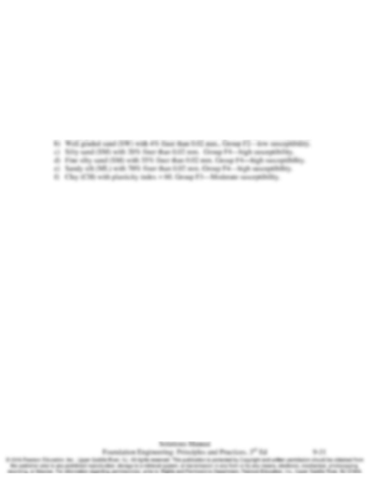
a) Sandy gravel (GW) with 3% finer than 0.02 mm. Group F1—very low susceptibility.

Chap. 9 Spread Footings-Geotechnical Design
9.20 A compacted fill is to be placed at a site in North Dakota. The following soils are available for
import: Soil 1 – silty sand; Soil 2 – lean clay; Soil 3 – Gravelly coarse sand. Which of these soils
would be least likely to have frost heave problems?
Solution
Soil-3, the gravelly course sand would be in Group F1, per Table 9.4, which is the group with the

Chap. 9 Spread Footings-Geotechnical Design
9.21 Would it be wise to use slab-on-grade floors for houses built on permafrost? Explain.
Solution

Chap. 9 Spread Footings-Geotechnical Design
9.22 What is the most common cause of failure in bridges?
Solution

Chap. 9 Spread Footings-Geotechnical Design
9.23 A single–story building is to be built on a sandy silt in Detroit. How deep must the exterior
footings be below the ground surface to avoid problems with frost heave?
Solution
To avoid frost heave, the footing should be at a depth below expected frost penetration. Using
Chap. 9 Spread Footings-Geotechnical Design
9.24 A column carries the following factored ultimate loads PU = 1200 kN and PN = 300 m-kN. The
service loads are PU = 950 kN and PN = 30 m-kN. The footing for this column is to be founded
at a depth of 1.5-m on a underlying cohesive soil with su = 200 kPa, Cr/(1+e0) = 0.040, and
OCR = 6. The design a footing for this column using LRFD.
Solution
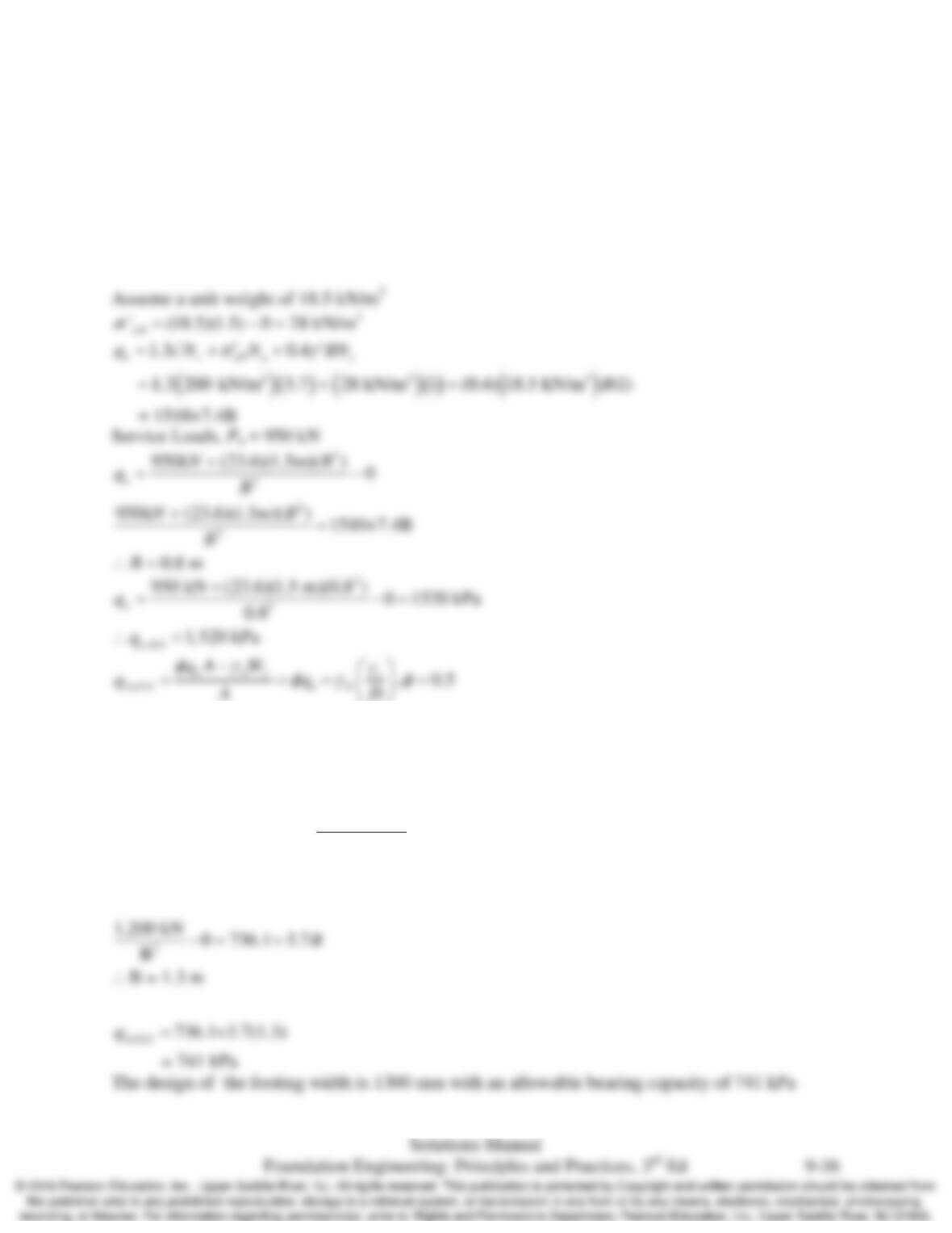
c′= su,
φ
’= 0o: Nc= 5.7, Nq= 1, Nγ= 1, from Table 7.1
( )
( )
( )
( )
( )
( )
22 3
3
,
1.3 0.4
0.5 1.3 200 kN/m 5.7 28 kN/m 1 (0.4) 18.5 kN/m (1)
= 755 + 3.7
23.6 kN/m
(755 3.7 ) 1.2 1.5 m
= 736.1+3.7
n c zD q
A ULS
q c N N BN
B
B
qB
γ
φφ σ γ
′′
= + +′
= ++
=+−
B
Chap. 9 Spread Footings-Geotechnical Design
9.25 A geotechnical engineer has provided the following design parameters for a cohesionless soil at a
certain site: qA = 4000 lb/ft2, μa = 0.41, KA = 0.33, KP = 3.0. The groundwater table is at a depth
of 20 ft. A column that is to be supported on a square spread footing on this soil will impart the
following ASD load combinations onto the footing: P = 200 k, V = 18 k. Determine the required
width and depth of embedment for a square footing to support this column.
Solution
Estimated minimum depth of embedment is 1.0 ft from Table 9.1
32
32
1
From Eq 3.39 (110 lb/ft )(7.2 ft)(1.0 ft) 1,188 lb
2
1
From Eq 3.37 (110 lb/ft )(7.2 ft)(1.0 ft) 131 lb
Pp
Aa
PK
PK
= =
= =

Chap. 9 Spread Footings-Geotechnical Design
9.26 Six cone penetration tests and four exploratory borings have been performed at the site of a
proposed warehouse building. The underlying soils are natural sands and silty sands with
occasional gravel. The CPT results and a synthesis of the borings are shown in Figure 9.17. The
warehouse will be supported on 3 ft deep square footings that will have ultimate LRFD design
downward loads of 100 to 600 k and serviceability loads of 100 to 480 k. The allowable total
settlement is 1.0 in and the allowable differential settlement is 0.5 in. Using ASD with these data
and reasonable factors of safety, develop design charts for vertical loads (both ultimate and
serviceability) and values of, μa, KA, and KP for lateral design.
Solution

Chap. 9 Spread Footings-Geotechnical Design
9.27 Using the design values in Problem 9.26, determine the required width of a footing that must
support the following ASD load combinations:
a. Max load combination: P = 200 k, V = 0
Service loads: P = 180 k, V = 0
b. Max load combination: P = 200 k, V = 21 k
Service loads: P = 180 k, V = 0
c. Max load combination: P = 440 k, V = 40 k
Service loads: P = 400 k, V = 0
d. Max load combination: P = 480 k, V = 40 k
Service loads: P = 360 k, V = 0
Solution