PROBLEM 9.40
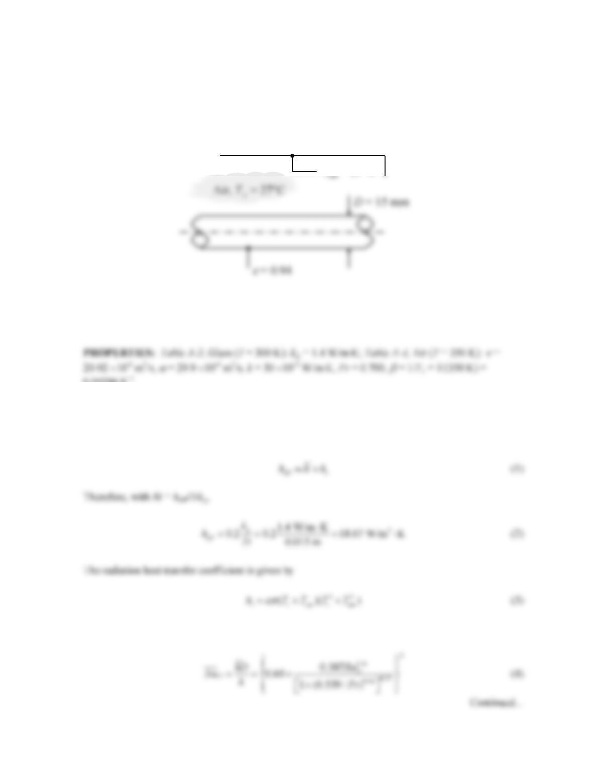
KNOWN: Diameter and emissivity of horizontal glass cylinder. Temperature of air and
surroundings.
FIND: Temperature at which lumped capacitance approximation may be applied.
SCHEMATIC:
ASSUMPTIONS: (1) The quasi-steady approximation holds: the heat transfer coefficient can be
evaluated based on steady–state conditions, (2) Air properties can be evaluated at 350 K, (3) Radiation
is to large surroundings.
0.00286 K-1.
ANALYSIS: The largest heat transfer coefficient for which the lumped capacitance approximation is
valid can be found from Bi = 0.1, where the characteristic length is the cylinder radius, ro. In this case,
the heat transfer coefficient should be the effective value that includes both convection and radiation,
The free convection heat transfer coefficient can be found from the Churchill-Chu correlation,
Tsur = 27°C
PROBLEM 9.40 (Cont.)
where the Rayleigh number is:
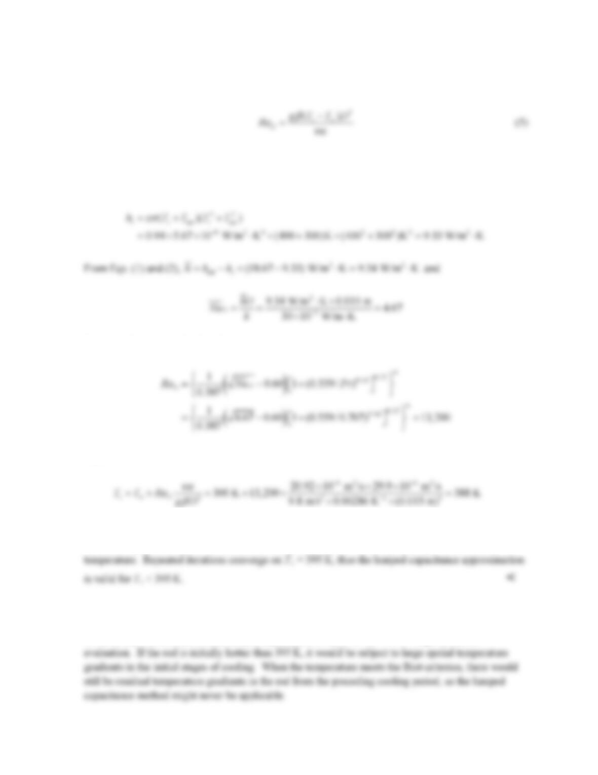
Equations (1)-(5) can be solved for the unknowns, including the surface temperature. This can easily
be done using IHT, but it can also be solved by hand as follows. We begin by taking Ts = 400 K for
the purpose of estimating the radiation heat transfer coefficient of Eq. (3):
Then Eq. (4) can be solved for RaD,
Eq. (5) can now be solved for Ts:
This is reasonably close to the initial assumption of Ts = 400 K. Greater accuracy could be obtained
by repeating the calculations with the new estimate of Ts and evaluating air properties at the film
COMMENTS: (1) Because of the relatively small thermal conductivity of glass, the effective heat
transfer coefficient must be fairly small, 18.67 W/m2 ⋅ K, for the lumped capacitance approximation to
be valid. (2) The conclusion that lumped capacitance is valid for Ts < 395 K requires further
PROBLEM 9.41
KNOWN: A long uninsulated steam line with a diameter of 100 mm and surface emissivity of 0.8
transports steam at 150°C and is exposed to atmospheric air and large surroundings at an equivalent
temperature of 20°C.
FIND: (a) The rate of heat loss per unit length for a calm day when the ambient air temperature is
20°C; (b) The rate of heat loss on a breezy day when the wind speed is 8 m/s; and (c) For the
conditions of part (a), calculate the rate of heat loss with 20-mm thickness of insulation (k = 0.08
W/m⋅K). Would the rate of heat loss change significantly with an appreciable wind speed?
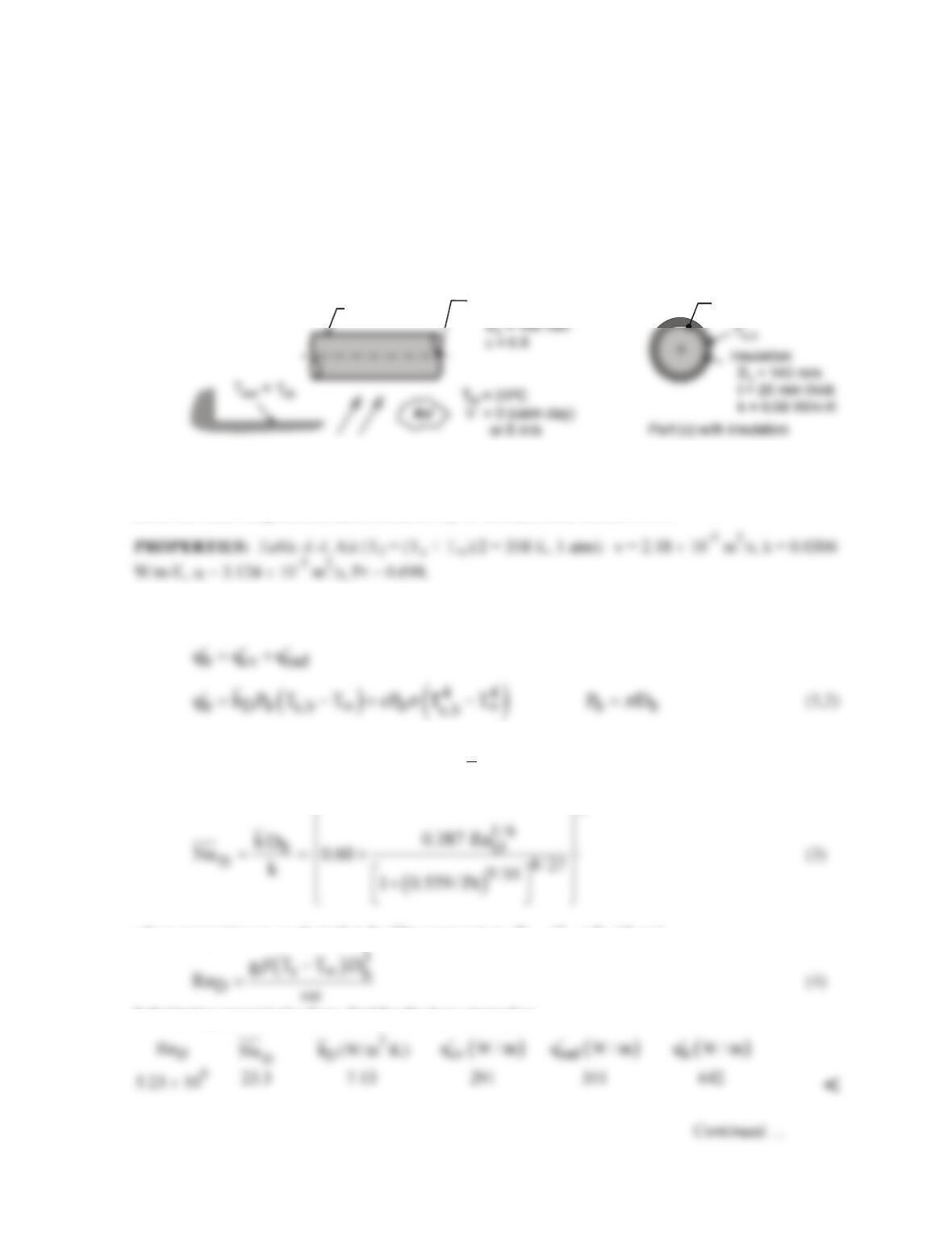
SCHEMATIC:
ASSUMPTIONS: (1) Steady-state conditions, (2) Calm day corresponds to quiescent ambient
conditions, (3) Breeze is in crossflow over the steam line, (4) Atmospheric air and large surroundings
are at the same temperature; and (5) Emissivity of the insulation surface is 0.8.
ANALYSIS: (a) The rate of heat loss per unit length from the pipe by convection and radiation
exchange with the surroundings is
where Db is the diameter of the bare pipe. Using the Churchill-Chu correlation, Eq. 9.34, for free
convection from a horizontal cylinder, estimate
D
h
2
where properties are evaluated at the film temperature, Tf = (Ts + T∞)/2 and
Substituting numerical values, find for the bare steam line
Ts,b
Steam line (bare)
Db = 89 mm
T = 200 C
s,b o
Ts,b = 150°C
PROBLEM 9.41 (Cont.)
(b) For forced convection conditions with V = 8 m/s, use the Churchill-Bernstein correlation, Eq.
7.54,
where ReD = VD/ν. Substituting numerical values, find
(c) With 20-mm thickness insulation, and for the calm-day condition, the heat loss rate per unit length
is
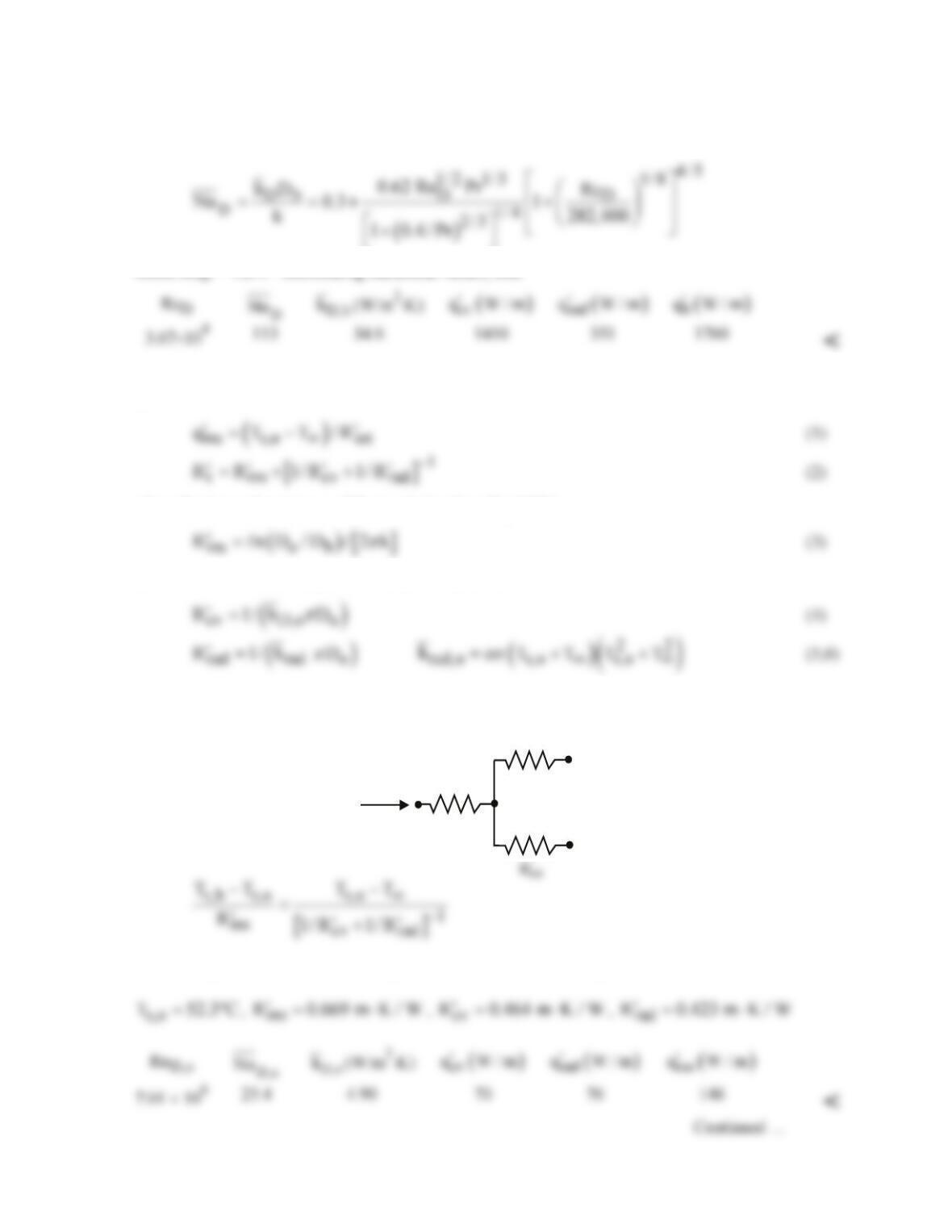
where the thermal resistance of the insulation from Eq. 3.33 is
and the convection and radiation thermal resistances are
The outer surface temperature of the insulation, Ts,o, can be determined by an energy balance on the
surface node of the thermal circuit.
T
o
o
T
o
o
T
sur
=
T
s,b
T
s,o
’
R
rad
’
R
ins
q’
Substituting numerical values with Do = 140 mm, find the following results.

PROBLEM 9.41 (Cont.)
The effect of increased wind speed is to reduce
cv
R,
′
increase
cv
q
,
′
and increase
ins
q.
′
The effect will
not be as significant as for the bare tube because of the presence of the significant resistance
associated with the insulation. <
COMMENTS: (1) For the calm-day conditions either with or without insulation, the rate of heat loss
by radiation exchange is more than 50% of the total loss. Using a reflective shield (say, ε = 0.1) on
the outer surface could reduce the heat loss rate significantly.
(2) The effect of an 8 m/s breeze over the uninsulated steam line is to increase the heat loss rate by
(3) The effect of the 20-mm thickness insulation is to reduce the heat loss to ~20% of the rate by free
convection or to <10% of the rate on the breezy day. From the results of part (c), note that the
(4) The convection correlation models in IHT are especially useful for applications such as the present
PROBLEM 9.42
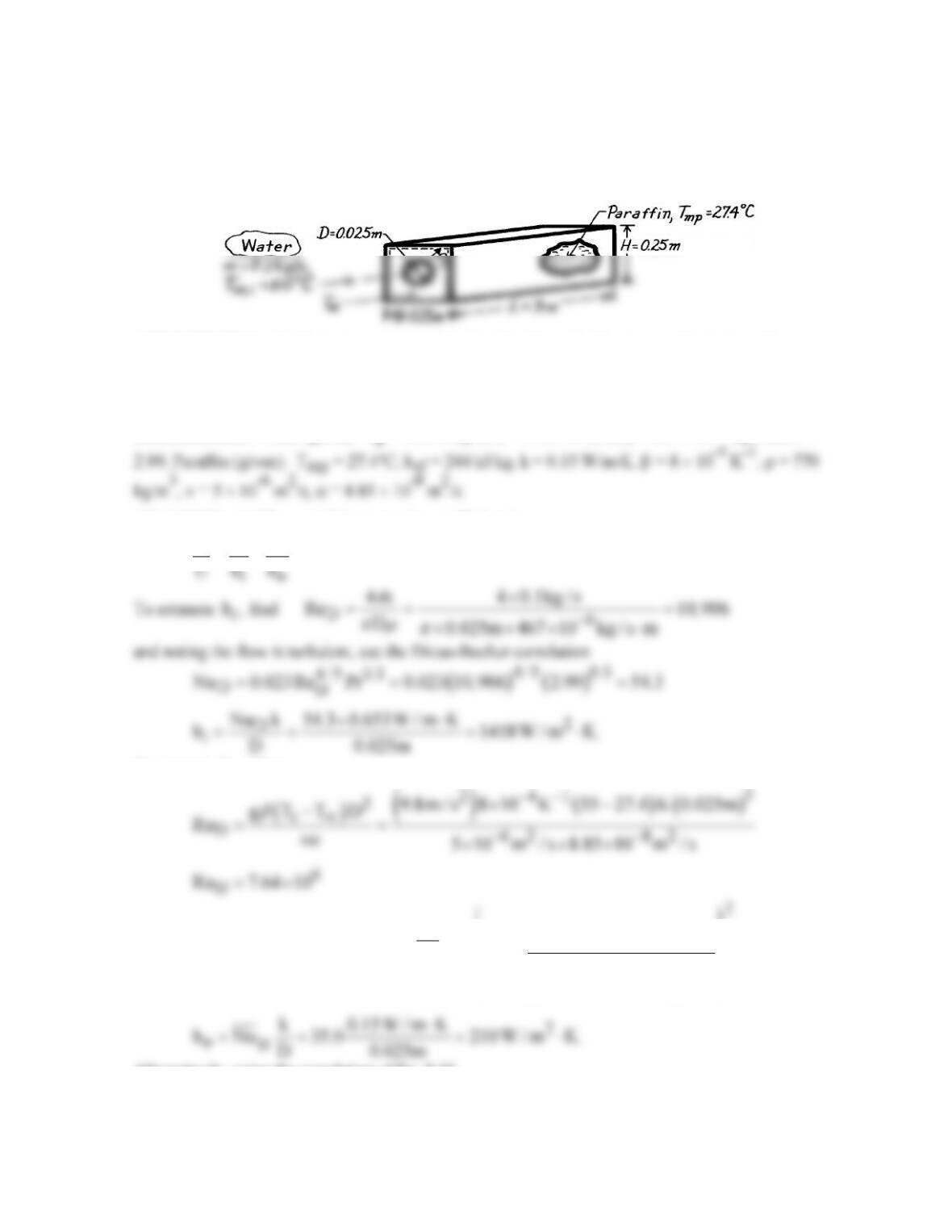
KNOWN: Length and diameter of tube submerged in paraffin of prescribed dimensions. Properties
of paraffin. Inlet temperature, flow rate and properties of water in the tube.
FIND: (a) Water outlet temperature, (b) Heat rate, (c) Time for complete melting.
SCHEMATIC:
ASSUMPTIONS: (1) Water is incompressible liquid with negligible viscous dissipation, (2)
Constant properties for water and paraffin, (3) Negligible tube wall conduction resistance, (4) Free
convection at outer surface associated with horizontal cylinder in an infinite quiescent medium, (5)
Negligible heat loss to surroundings, (6) Fully developed flow in tube.
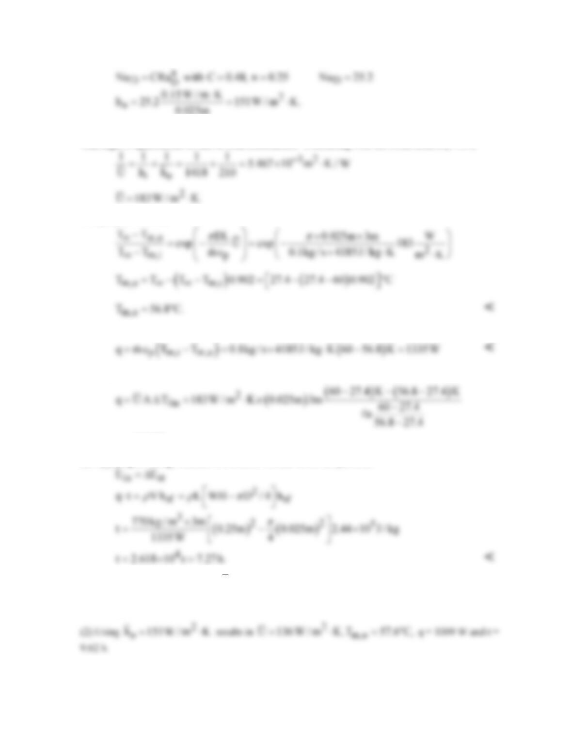
PROPERTIES: Water (given): cp = 4185 J/kg⋅K, k = 0.653 W/m⋅K, m = 467 × 10-6 kg/s⋅m, Pr =
ANALYSIS: (a) The overall heat transfer coefficient is
111
.
= +
To estimate
o
h,
find
and using the correlation of Eq. 9.34,
( )
D
1/6
D
8 / 27
9 /16
0.387 Ra
Nu 0.60 35.0
1 0.559 / Pr
=+=
+
Alternatively, using the correlation of Eq. 9.33,
Continued …
PROBLEM 9.42 (Cont.)
The significant difference in ho values for the two correlations may be due to difficulties associated
with high Pr applications of one or both correlations. Continuing with the result from Eq. 9.34,
Using Eq. 8.45a, find
(b) From an energy balance, the heat rate is
or using the rate equation,
q 1335 W.=
(c) Applying an energy balance to a control volume about the paraffin,
COMMENTS: (1) The value of
o
h
is overestimated by assuming an infinite quiescent medium.
The fact that the paraffin is enclosed will increase the resistance due to free convection and hence
decrease q and increase t.
PROBLEM 9.43
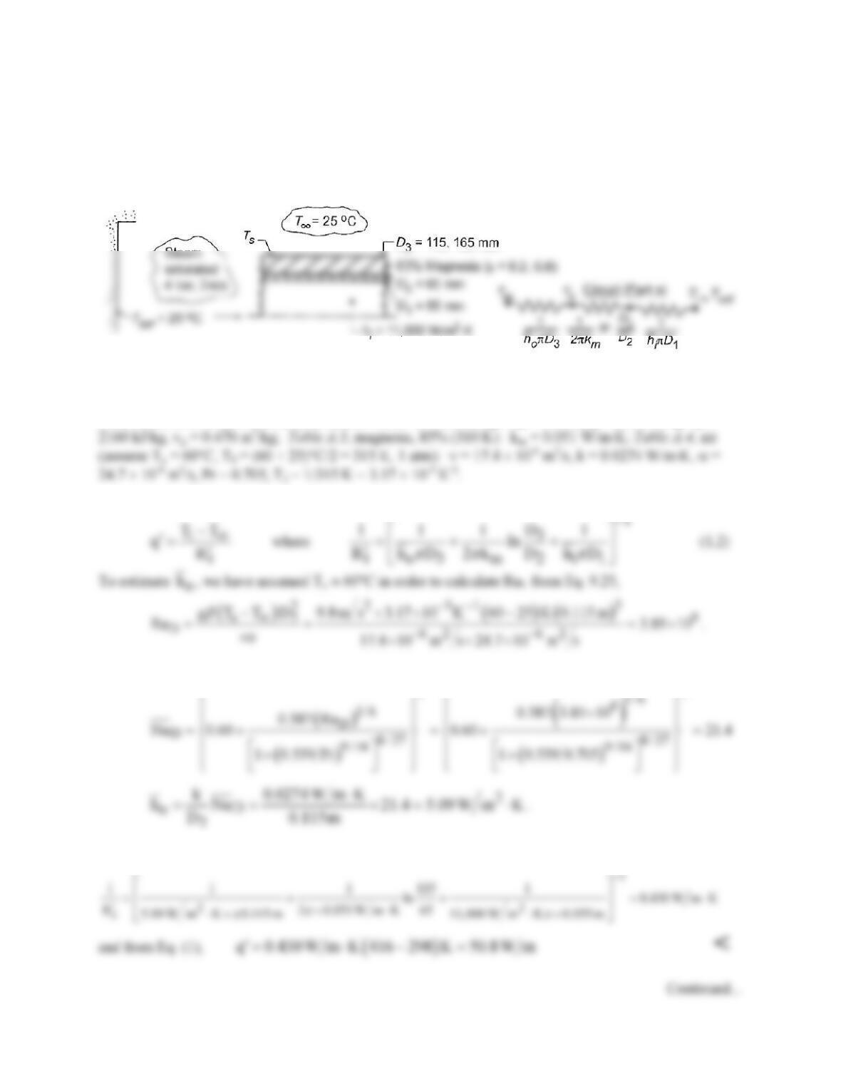
KNOWN: Insulated steam tube exposed to atmospheric air and surroundings at 25°C.
FIND: (a) Heat transfer rate by free convection to the room, per unit length of the tube; effect on
quality, x, at outlet of 30 m length of tube; (b) Effect of radiation on heat transfer and quality of outlet
flow; (c) Effect of emissivity and insulation thickness on heat rate.
SCHEMATIC:
ASSUMPTIONS: (1) Ambient air is quiescent, (2) Negligible surface radiation (part a), (3) Tube wall
resistance negligible.
PROPERTIES: Steam tables, steam (sat., 4 bar): if = 566 kJ/kg, Tsat = 416 K, ig = 2727 kJ/kg, ifg =
ANALYSIS: (a) The heat rate per unit length of the tube (see sketch) is given as,
The appropriate correlation is Eq. 9.34; find
22
Substituting numerical values into Eq. (2), find
PROBLEM 9.43 (Cont.)
We need to verify that the assumption of Ts = 60°C is reasonable. From the thermal circuit,
()
2
s o3
T T q h D 25 C 50.8 W m 5.09 W m K 0.115 m 53 C
pp
∞′
= + = + ⋅×× =
.
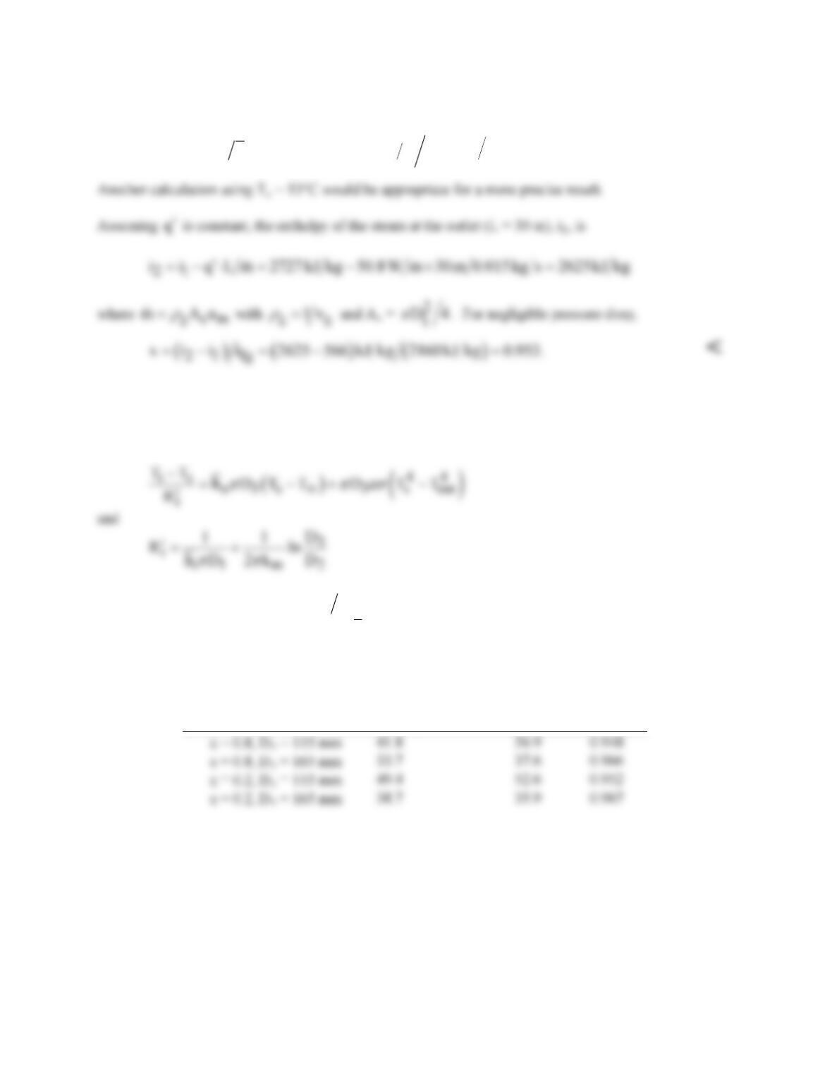
(b) With radiation, we first determine Ts by performing an energy balance at the outer surface, where
i conv,o rad
qq q
′′ ′
= +
From knowledge of Ts,
( )
i is i
q TTR
′′
= −
may then be determined. Using the Correlations and
Properties Tool Pads of IHT to determine
ho
and the properties of air evaluated at Tf = (Ts +
T¥
)/2, the
following results are obtained.
(c)
Condition
T
s
(°C)
i
q′
(W/m) x
<
COMMENTS: Clearly, a significant reduction in heat loss may be realized by increasing the insulation
thickness. Although Ts, and hence
conv,o
q′
, increases with decreasing ε, the reduction in
rad
q′
is more
than sufficient to reduce the heat loss.
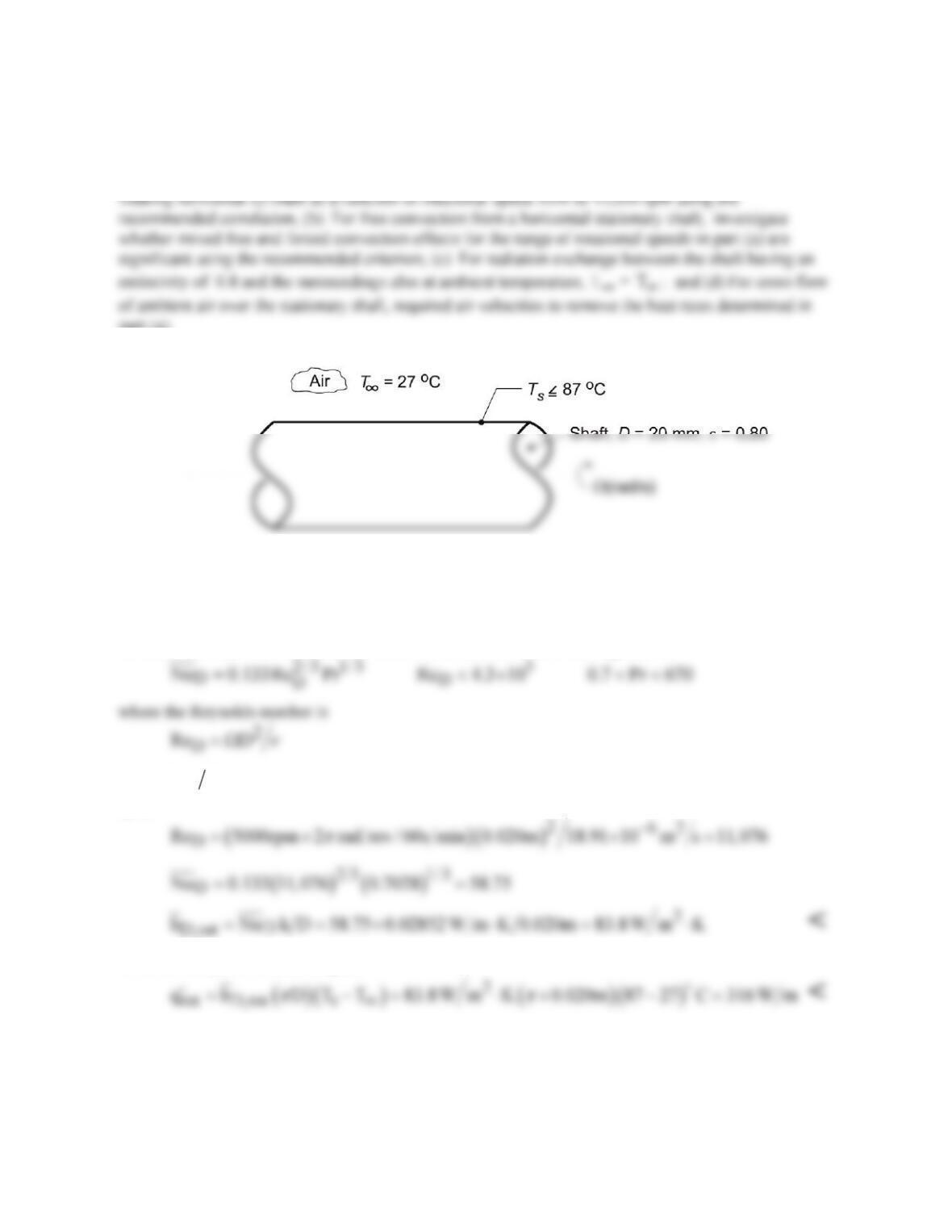
PROBLEM 9.44
KNOWN: Motor shaft of 20-mm diameter operating in ambient air at
T
∞
= 27°C with surface
temperature Ts ≤ 87°C.
FIND: Convection coefficients and/or heat removal rates for different heat transfer processes: (a) For a
part (a).
SCHEMATIC:
ASSUMPTIONS: (1) Steady-state conditions, (2) Shaft is horizontal with isothermal surface.
PROPERTIES: Table A.4, Air (Tf = (Ts +
T
∞
)/2 = 330 K, 1 atm): ν = 18.91 × 10⁻⁶ m2/s , k = 0.02852
W/m⋅K, α = 26.94 × 10⁻⁶ m2/s, Pr = 0.7028, β = 1/Tf .
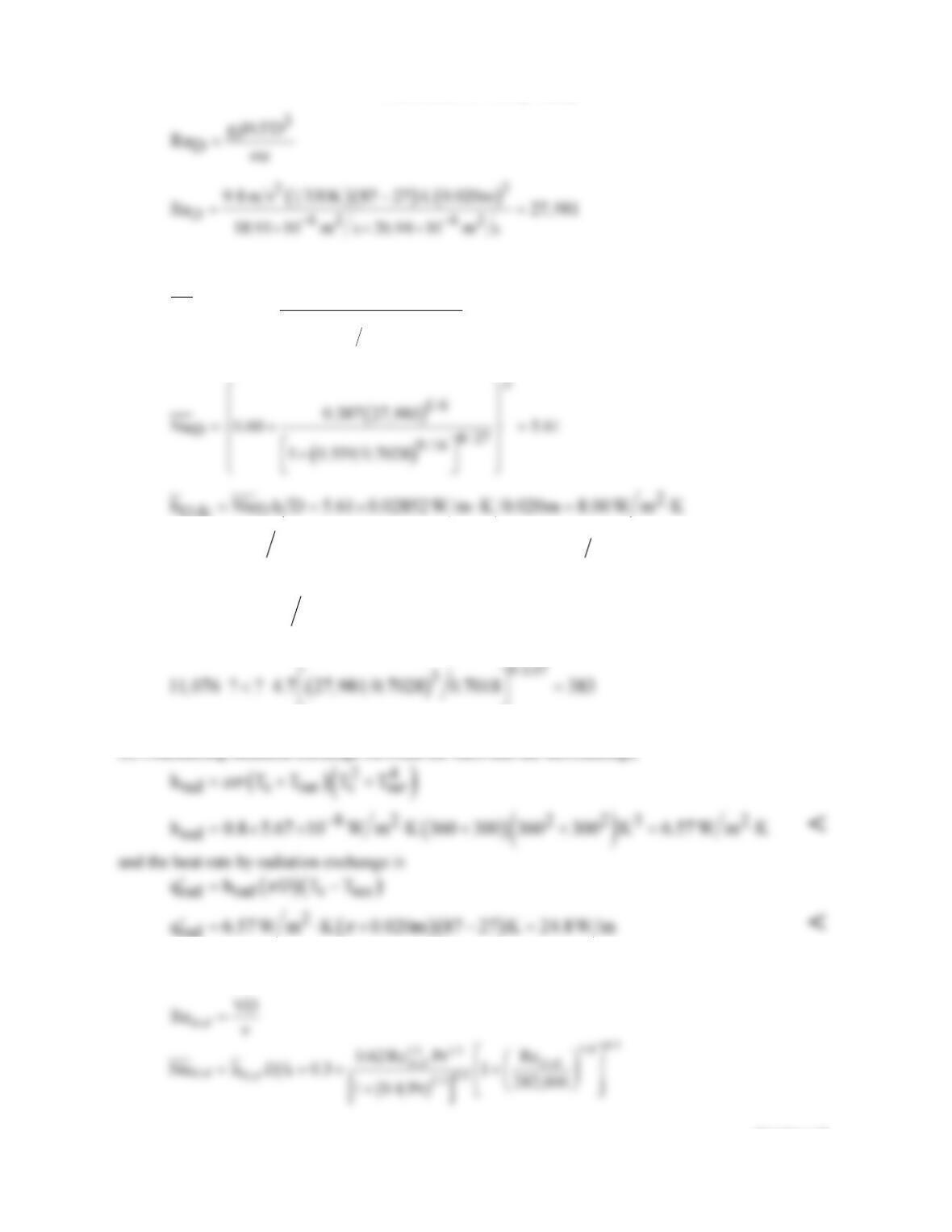
ANALYSIS: (a) The recommended correlation for a horizontal rotating shaft is
and Ω
( )
rad s
is the rotational velocity. Evaluating properties at Tf = (Ts +
T
∞
)/2, find for ω = 5000
rpm,
The heat rate per unit shaft length is
The convection coefficient and heat rate as a function of rotational speed are shown in a plot below.
(b) For the stationary shaft condition, the free convection coefficient can be estimated from the
Churchill-Chu correlation, Eq. (9.34) with
Continued…
T
∞
PROBLEM 9.44 (Cont.)
( )
2
1/6
D
D8 / 27
9 /16
0.387Ra
Nu 0.60
1 0.559 Pr
= +
+
D,fc
( )( )
2
fc
q 8.00 W m K 0.020m 87 27 C 30.2 W m
p
′= ⋅× − =
<
Mixed free and forced convection effects may be significant if
()
0.137
3
DD
Re 4.7 Gr Pr<
where GrD = RaD/Pr, find using results from above and in part (a) for ω = 5000 rpm,
We conclude that free convection effects are not significant for rotational speeds above 5000 rpm.
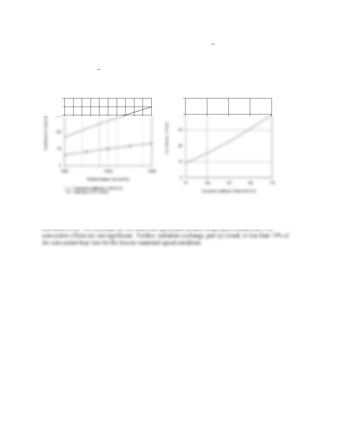
(c) Considering radiation exchange between the shaft and the surroundings,
rad
(d) For cross flow of ambient air at a velocity V over the shaft, the convection coefficient can be
estimated using the Churchill-Bernstein correlation, Eq. 7.54, with
Continued…
PROBLEM 9.44 (Cont.)
From the plot below (left) for the rotating shaft condition of part (a),
D,rot
h
vs. rpm, note that the
convection coefficient varies from approximately 75 to 175 W/m2
⋅
K. Using the IHT Correlations
Tool, Forced Convection, Cylinder, which is based upon the above relations, the range of air velocities
V required to achieve
D,cf
h
in the range 75 to 175 W/m2
⋅
K was computed and is plotted below
(right).
200
40
50
Note that the air cross–flow velocities are quite substantial in order to remove similar heat rates for the
rotating shaft condition.
PROBLEM 9.45
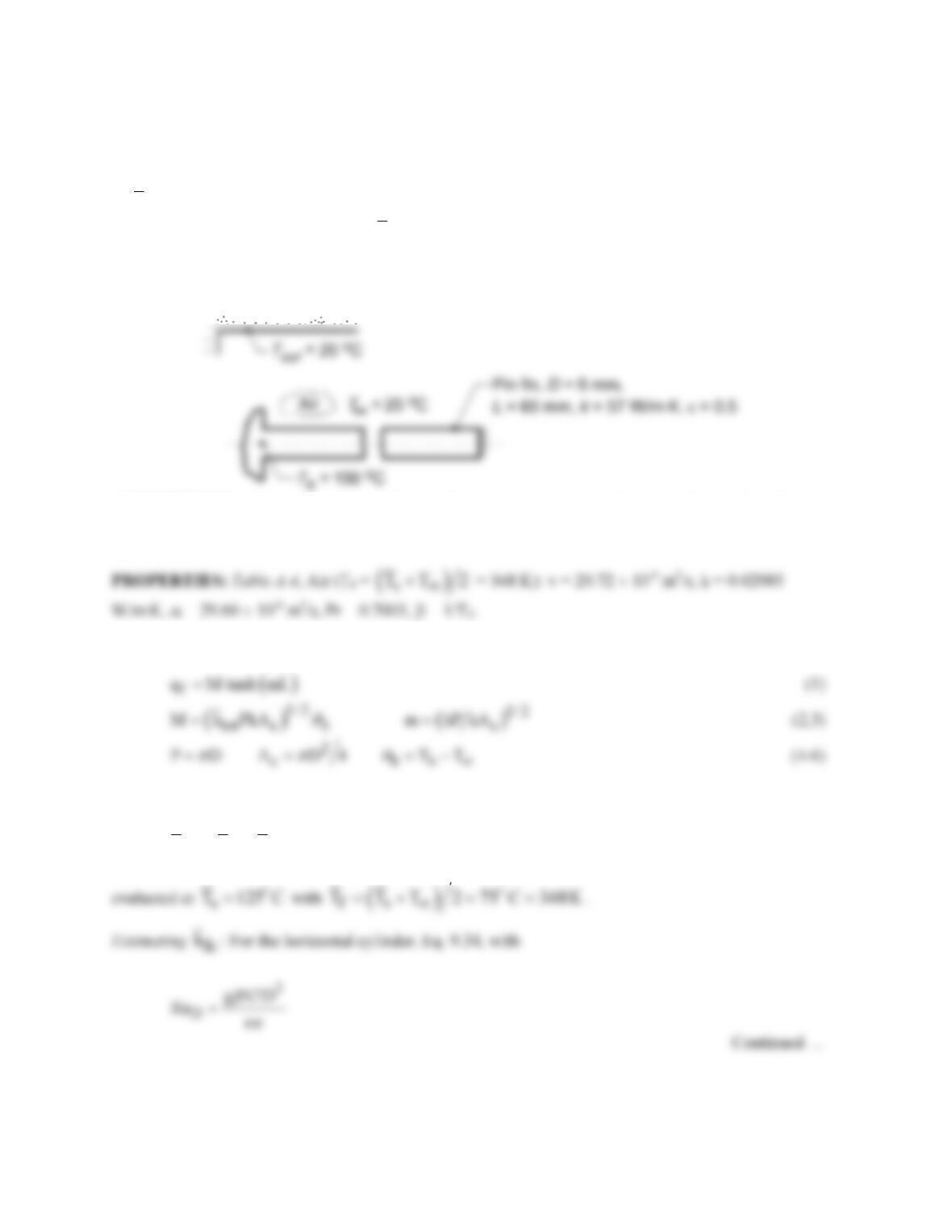
KNOWN: Horizontal pin fin of 6-mm diameter and 60-mm length fabricated from plain carbon steel (k
= 57 W/m⋅K, ε = 0.5). Fin base maintained at Tb = 150°C. Ambient air and surroundings at 25°C.
FIND: Fin heat rate, qf, by two methods: (a) Analytical solution using average fin surface temperature
of
s
T 125 C=
to estimate the free convection and linearized radiation coefficients; comment on
sensitivity of fin heat rate to choice of
s
T
; and, (b) Finite–difference method when coefficients are based
upon local temperatures, rather than an average fin surface temperature; compare result of the two
solution methods.
SCHEMATIC:
ASSUMPTIONS: (1) Steady-state conditions, (2) One-dimensional conduction in the pin fin, (3)
Ambient air is quiescent and extensive, (4) Surroundings are large compared to the pin fin, and (5) Fin
tip is adiabatic.
ANALYSIS: (a) The heat rate for the pin fin with an adiabatic tip condition is, Eq. 3.81,
and the average coefficient is the sum of the convection and linearized radiation processes, respectively,
tot fc rad
h hh= +
(7)
PROBLEM 9.45 (Cont.)
( )( )( )
3
2
D62 62
9.8 m s 1 348K 125 25 0.006m
Ra 991.79
20.72 10 m s 29.60 10 m s
−−
−
= =
× ××
D
fc
Calculating
rad
h
: The linearized radiation coefficient is
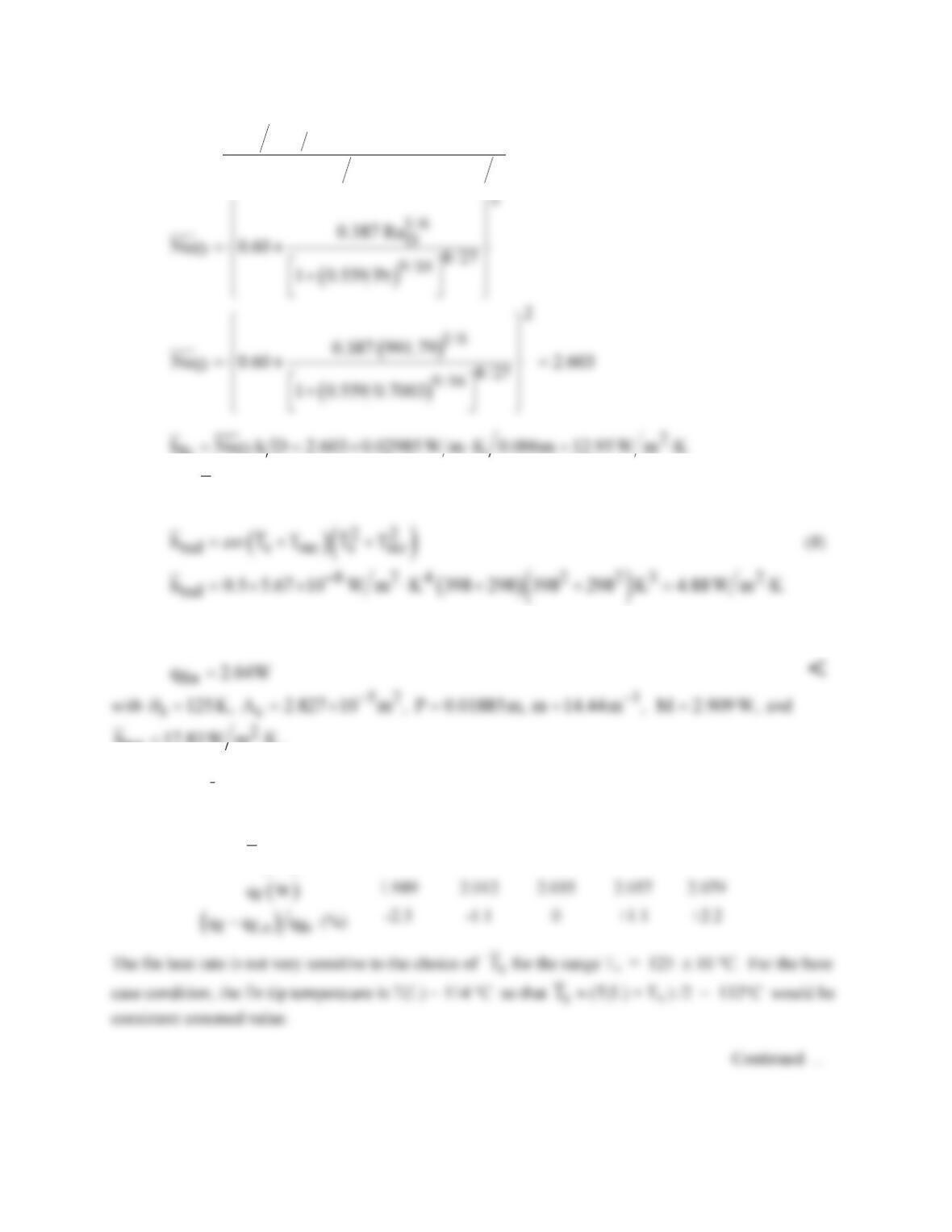
Substituting numerical values into Eqs. (1-7) , find
tot
h 17.83W m K= ⋅
.
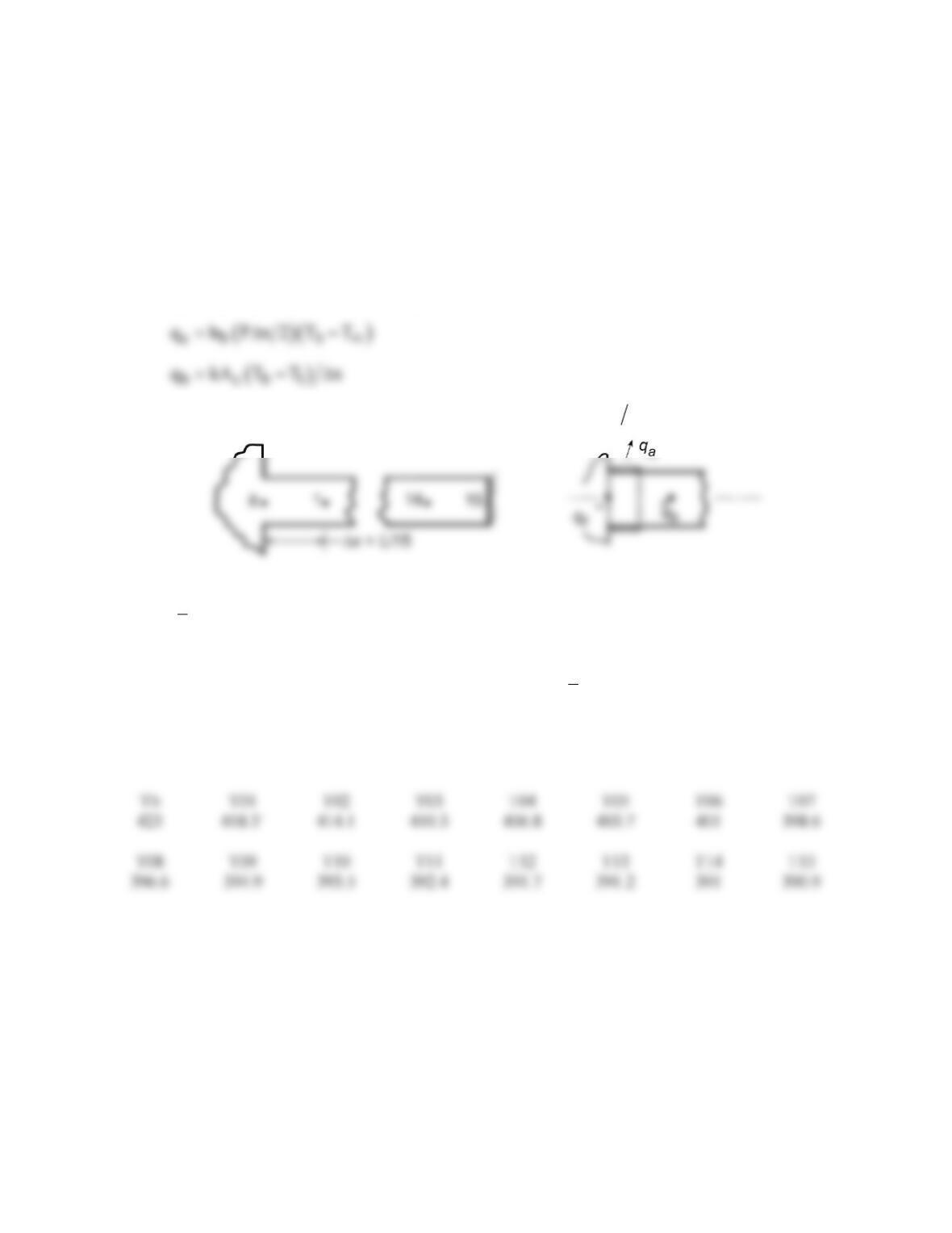
Using the IHT Model, Extended Surfaces, Rectangular Pin Fin, with the Correlations Tool for Free
Convection and the Properties Tool for Air, the above analysis was repeated to obtain the following
results.
()
s
TC
115
120
125
130
135
PROBLEM 9.45 (Cont.)
(b) Using the IHT Tool, Finite-Difference Equation, Steady- State, Extended Surfaces, the temperature
distribution was determined for a 15-node system from which the fin heat rate was determined. The local
free convection and linearized radiation coefficients
tot fc rad,
h hh= +
were evaluated at local
temperatures, Tm , using IHT with the Correlations Tool, Free Convection, Horizontal Cylinder, and the
Properties Tool for Air, and Eq. (8). The local coefficient htot vs. Ts is nearly a linear function for the
range 114 ≤ Ts ≤ 150°C so that it was reasonable to represent htot (Ts) as a Lookup Table Function. The
fin heat rate follows from an energy balance on the base node, (see schematic next page)
( )
f ab
q q q 0.08949 1.879 W 1.97 W=+= + =
<
where Tb = 150°C, T1 = 418.3 K = 145.3°C, and hb = htot (Tb) = l8.99 W m K
2⋅.
Considering variable coefficients, the fin heat rate is -3.3% lower than for the analytical solution with the
assumed
s
T
= 125°C.
COMMENTS: (1) To validate the FDE model for part (b), we compared the temperature distribution
and fin heat rate using a constant htot with the analytical solution (
s
T
= 125°C). The results were
identical indicating that the 15–node mesh is sufficiently fine.
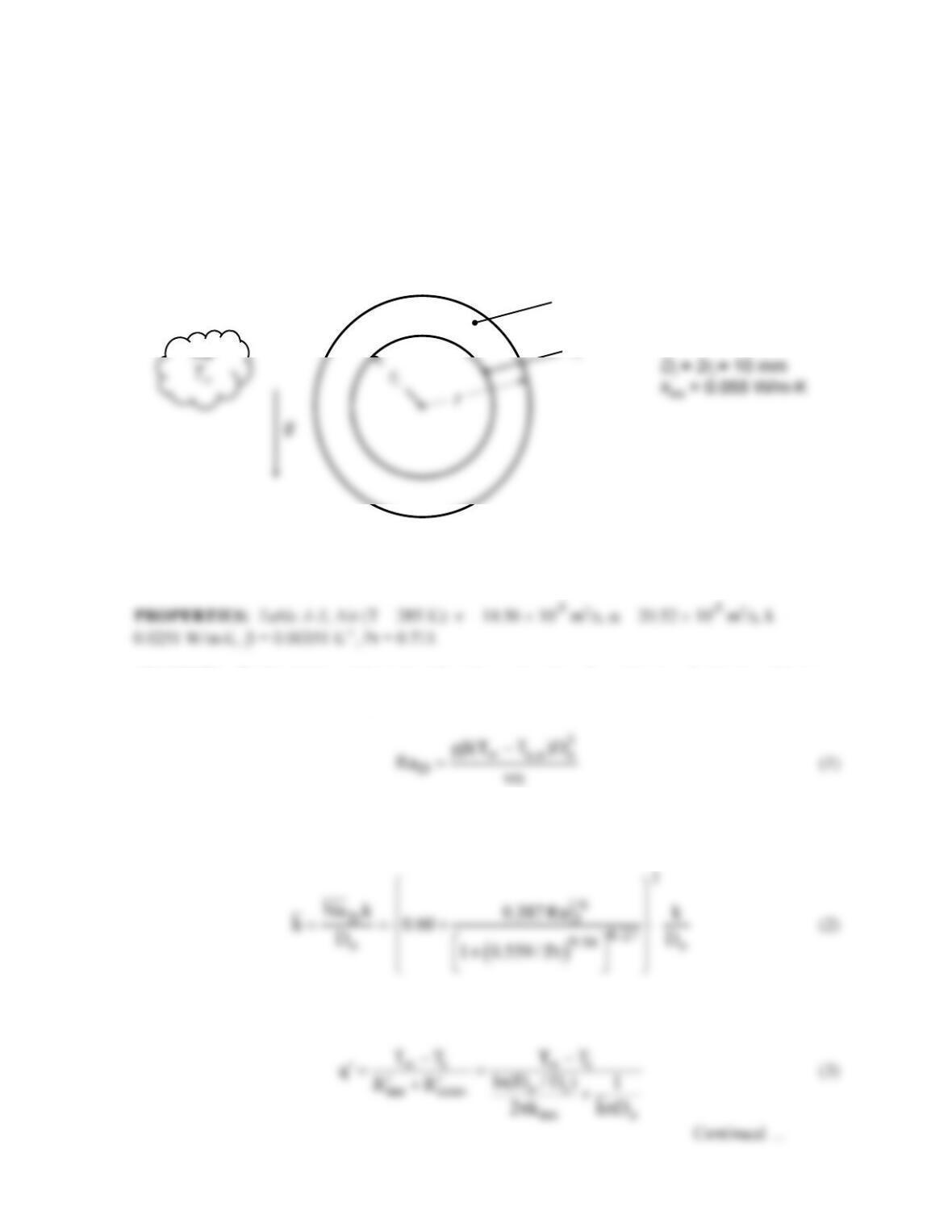
(2) The fin temperature distribution (K) for the IHT finite-difference model of part (b) is
PROBLEM 9.46
KNOWN: Diameter and temperature of thin-walled copper tube. Thermal conductivity and thickness
of insulation. Temperature of quiescent air environment.
FIND: For a tube diameter of 10 mm: Heat transfer rate per unit length, neglecting radiation, for
insulation thickness of 10 mm. Conduction, convection, and total thermal resistances for the range of
insulation thicknesses from 0 to 50 mm. Repeat for a tube diameter of 1 mm. For each case, determine
if a critical insulation thickness exists and explain why or why not.
SCHEMATIC:
Insulation
T
T
i
= –10°C
T
∞
= 25°C
ASSUMPTIONS: (1) Steady–state conditions, (2) One-dimensional (radial) heat transfer, (3)
Negligible thermal resistance of tube wall, (4) Negligible radiation, (5) Constant properties.
ANALYSIS: The Rayleigh number is based on the outer radius, Do = 10 mm + 2×10 mm = 30 mm.
The outer surface temperature, Ts,o, isn’t known yet.
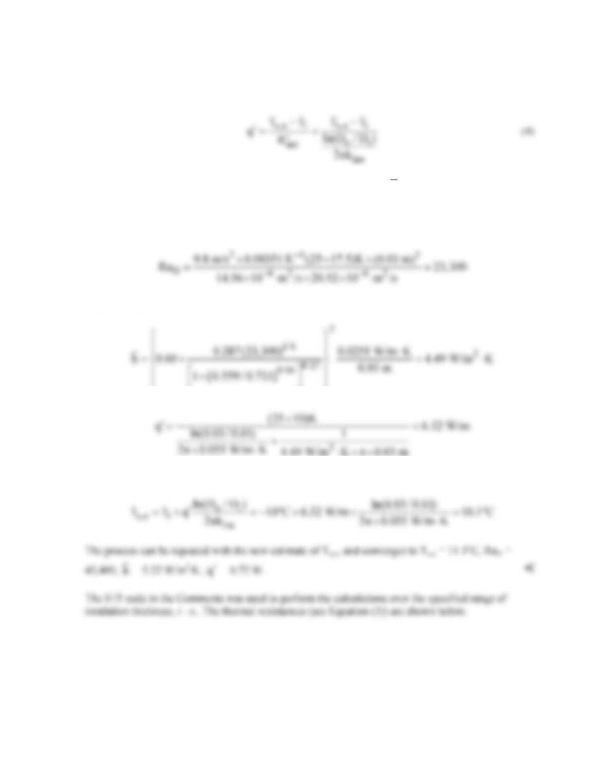
Assuming RaD < 1012, Equation 9.34 can be used for the Nusselt number, so that the heat transfer
coefficient is:
The heat transfer rate per unit length is given by:
PROBLEM 9.46 (Cont.)
In order to find the outer surface temperature, an additional relationship can be written for the heat
transfer rate:
Equations (1) through (4) can be solved for the four unknowns, RaD,
h,
Ts,o, and
q.
′
An IHT code for
this purpose is shown in the Comments section. We proceed to solve the first iteration of one case by
hand. We begin by assuming that Ts,o = (Ti + T∞)/2 = 17.5°C. Then, evaluating Eq. (1) with Do = 10
mm + 2×10 mm = 30 mm:
Equations (2) and (3) can be evaluated:
Solving Equation (4) for Ts,o:
Continued …
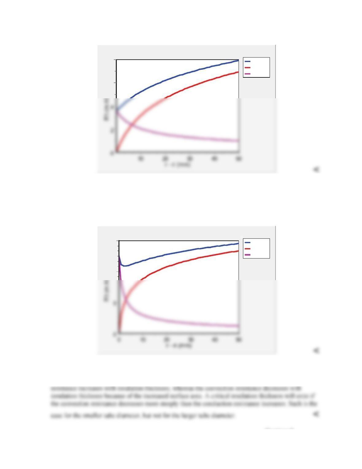
PROBLEM 9.46 (Cont.)
R‘t,tot
R‘t,cond
R‘t,conv
8
6
Comparing with Example 3.6, it can be seen that the total thermal resistance does not have a
minimum. Therefore there is no critical insulation thickness in this case. <
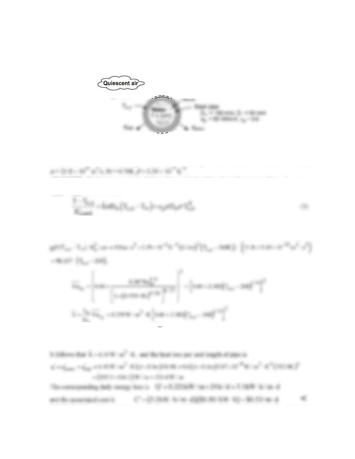
Repeating the calculations for a tube diameter of 1 mm, the results are shown below.
R‘t,tot
R‘t,cond
R‘t,conv
15
10
In this case, there is a critical insulation thickness of around 2 mm. <
To understand why there is or is not a critical insulation thickness, we observe that the conduction
Continued …

PROBLEM 9.46 (Cont.)
COMMENTS: (1) The critical radius is smaller for the natural convection case than for the
forced convection case in Example 3.6. (2) The IHT code is below.
//Model after Example 3.6 of 7e
//Insulation
kins = 0.055
//Dimensions
Dtube = 0.01
//Specify air properties at 285
Tf = 285
// Air property functions : From Table A.4
Rtotprim = Rcondprim + Rconvprim
NuD = NuD_bar_FC_HC(RaD,Pr) // Eq 9.34
PROBLEM 9.47
KNOWN: Diameter, thickness, emissivity and thermal conductivity of steel pipe. Temperature of
water flow in pipe. Cost of producing hot water.
FIND: Cost of daily heat loss from an uninsulated pipe.
SCHEMATIC:
T = -5 C
o
o
o
ASSUMPTIONS: (1) Steady-state, (2) Negligible convection resistance for water flow, (3)
Negligible radiation from pipe surroundings, (4) Quiescent air, (5) Constant properties.
PROPERTIES: Table A-4, air (p = 1 atm, Tf ≈ 295K): ka = 0.0259 W/m⋅K.
ν
= 15.45 × 10⁻⁶ m2/s,
ANALYSIS: Performing an energy balance for a control surface about the outer surface,
cond
q′=
conv rad
q q,
′′
+
it follows that
cond
where
( ) ( ) ( )
4
cond o i p
R n D / D / 2 k n 100 / 84 / 2 60 W / m K 4.62 10 m K / W.
pp
−
′= = ⋅= × ⋅
The
convection coefficient may be obtained from the Churchill and Chu correlation. Hence, with RaD =
o
Substituting the foregoing expression for
h
, as well as values of
cond o p
R , D , and
εs
′
into Eq. (1),
an iterative solution yields
s,o
T 322.9 K 49.9 C= = °
COMMENTS: (1) The heat loss is significant, and the pipe should be insulated. (2) The conduction
resistance of the pipe wall is negligible relative to the combined convection and radiation resistance at
the outer surface. Hence, the temperature of the outer surface is only slightly less than that of the
water.