6)();
wire [1: H_bin_size*N_bins] Histogram_bits;
wire Ready, Valid, Wait__P1, Wait_P2, Wait_P3, Wait_P4, Wait_P5, Wait_P6;
reg [1: pixel_size * N_col * M_row] pixel_bits;
reg Go, clk, reset;
wire [H_bin_size: 0] Level1 = Histogram_bits [1: H_bin_size];
wire [H_bin_size: 0] Level2 = Histogram_bits [1 + H_bin_size: 2*H_bin_size];
// Instantiate image converter
Image_Histogram_Concurrent_Processors M0 (Histogram_bits, Ready, Valid, Wait_1, Wait_2,
Wait_3, Wait_4, Wait_5, Wait_6, pixel_bits, Go, clk, reset);
initial begin
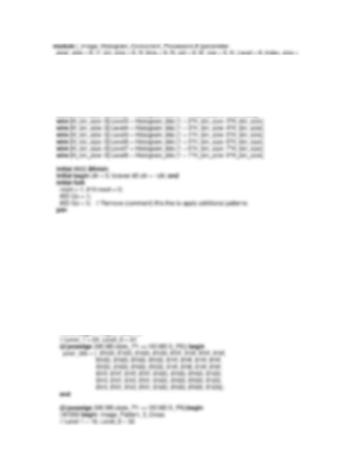
begin: Image_Pattern_1
// Level 1 = 24, Level_8 = 24
pixel_bits = { 8’hff, 8’hff, 8’hff, 8’hff, 8’h00, 8’h00, 8’h00, 8’h00,
8’hff, 8’hff, 8’hff, 8’hff, 8’h00, 8’h00, 8’h00, 8’h00,
8’hff, 8’hff, 8’hff, 8’hff, 8’h00, 8’h00, 8’h00, 8’h00,
8’h00, 8’h00, 8’h00, 8’h00, 8’hff, 8’hff, 8’hff, 8’hff,
8’h00, 8’h00, 8’h00, 8’h00, 8’hff, 8’hff, 8’hff, 8’hff,
8’h00, 8’h00, 8’h00, 8’h00, 8’hff, 8’hff, 8’hff, 8’hff};
end
//#500 begin: Image_Pattern_2
pixel_bits = { 8’h00, 8’h00, 8’hff, 8’hff, 8’hff, 8’hff, 8’h00, 8’h0,
8’h00, 8’h00, 8’hff, 8’hff, 8’hff, 8’hff, 8’h00, 8’h00,
@(posedge (M0.M0.state_P1 == M0.M0.S_P6)) begin
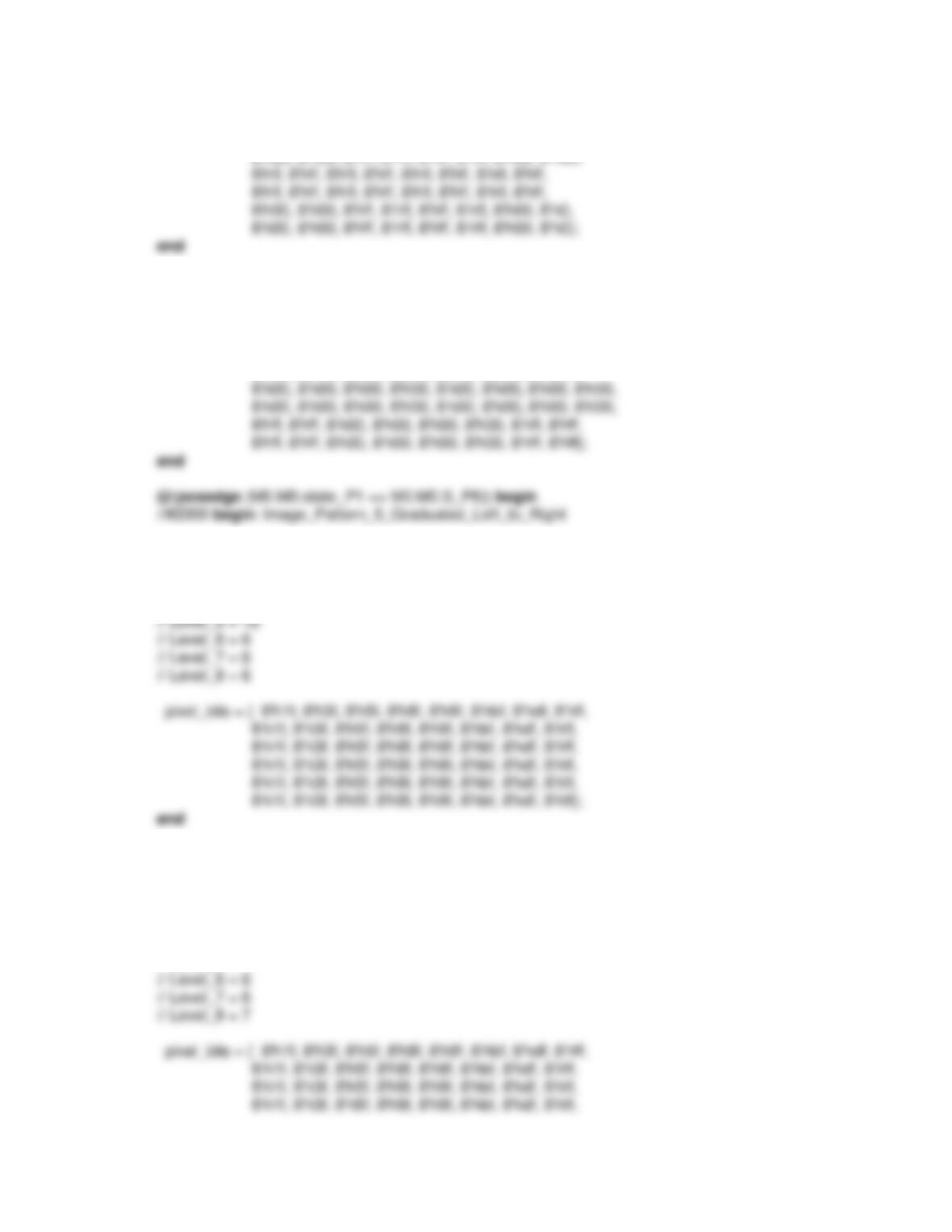
//#1500 begin: Image_Pattern_4_Bar_Cross
// Level_1 = 32, Level_8 = 16
pixel_bits = { 8’hff, 8’hff, 8’h00, 8’h00, 8’h00, 8’h00, 8’hff, 8’hff,
8’hff, 8’hff, 8’h00, 8’h00, 8’h00, 8’h00, 8’hff, 8’hff,
// Level_1 = 6
// Level_2 = 6
// Level_3 = 6
// Level_4 = 0
@(posedge (M0.M0.state_P1 == M0.M0.S_P6)) begin
//#2500 begin: Image_Pattern_6_Mixed_Values
// Level_1 = 5
// Level_2 = 6
// Level_3 = 6
// Level_4 = 1
// Level_5 = 11
8’h1f, 8’h3f, 8’h5f, 8’h8f, 8’h9f, 8’hbf, 8’hdf, 8’hff,
8’d32, 8’d64, 8’d96, 8’d128, 8’d160, 8’d192, 8’d224, 8’d255};
end
end
endmodule
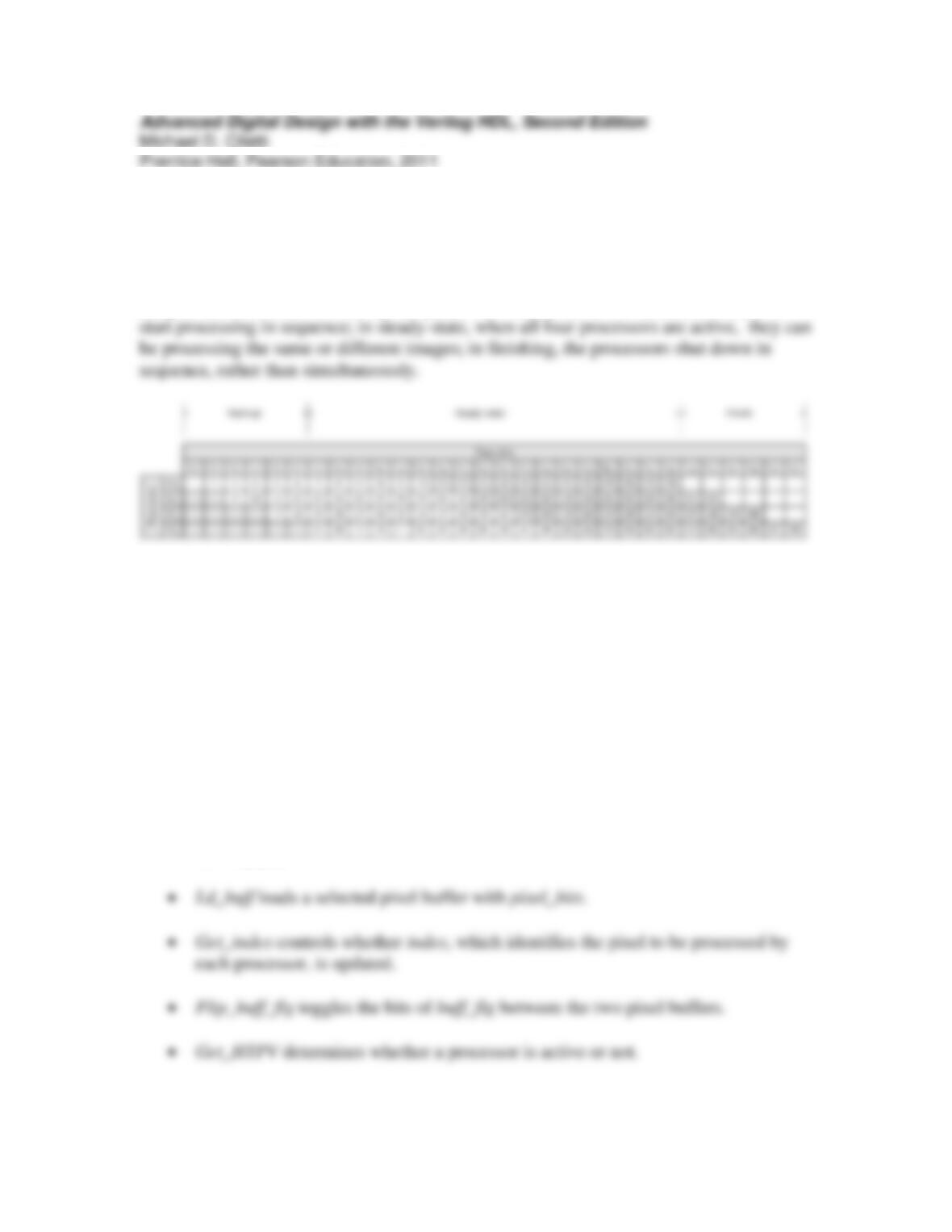
Problem 9-8
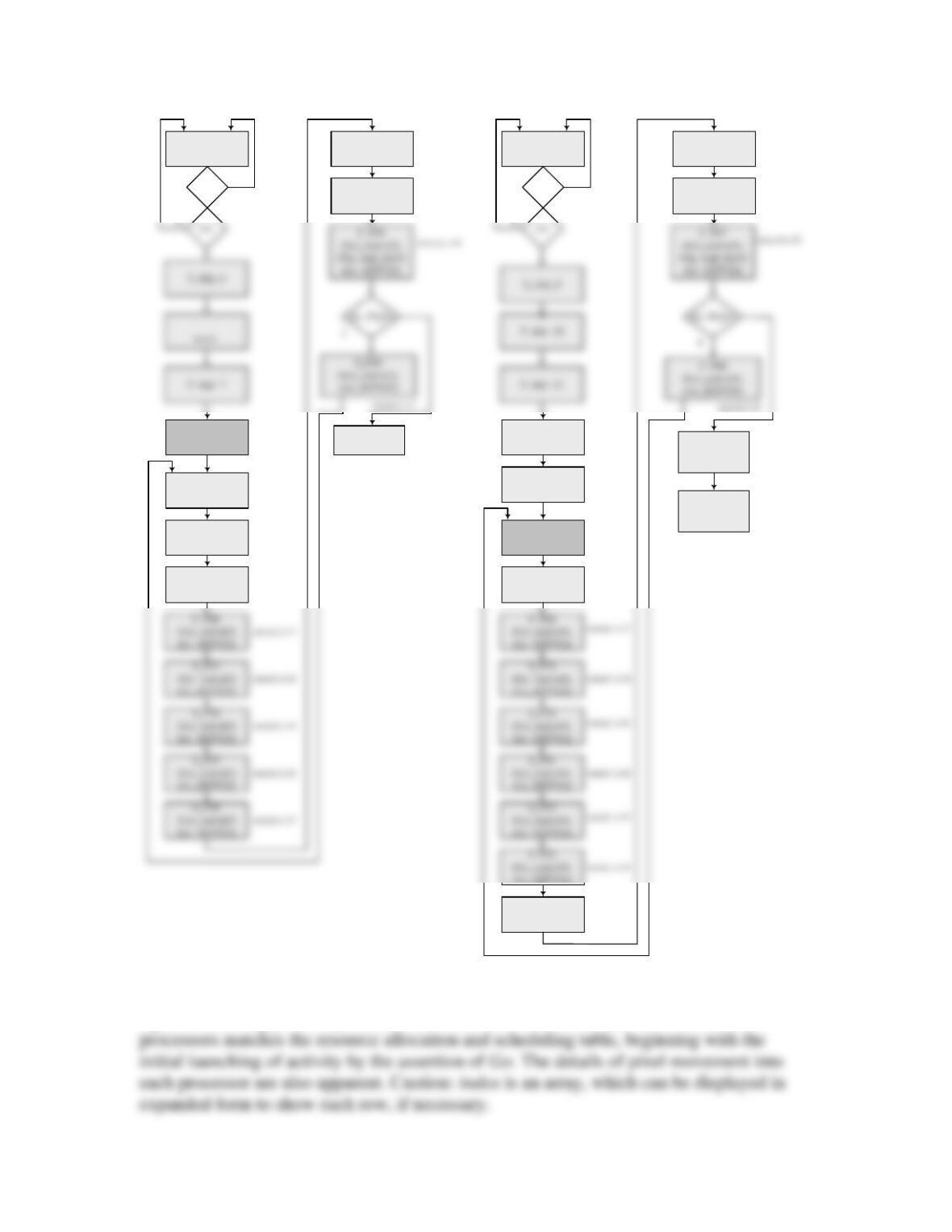
The resource scheduling table for concurrent streaming operation of the four processors
of the machine is shown below. The processing sequence for two images is shown to
illustrate the need to consider (a) start-up, (b) steady-state processing of (multiple)
images, and (b) finish. In start-up, the processors are not all active simultaneously, but
Observations: (1) The machine must have an output buffer so that a completely processed
image can be stored. Otherwise, the concurrent processing will overwrite an image before
it is read by the host processor. (2) The machine’s controller must respond to de-assertion
of Go followed by re-assertion of Go by terminating the action of each processor when it
completes its pixels. Otherwise, Go can be toggled to re-activate some but not all of the
processors, partially processing the image, but incorrectly indicating a completely
processed image. This observation will be discussed with the ASMD chart of the
machine. (3) The machine must include a signal to indicate that the output bus holds valid
data.
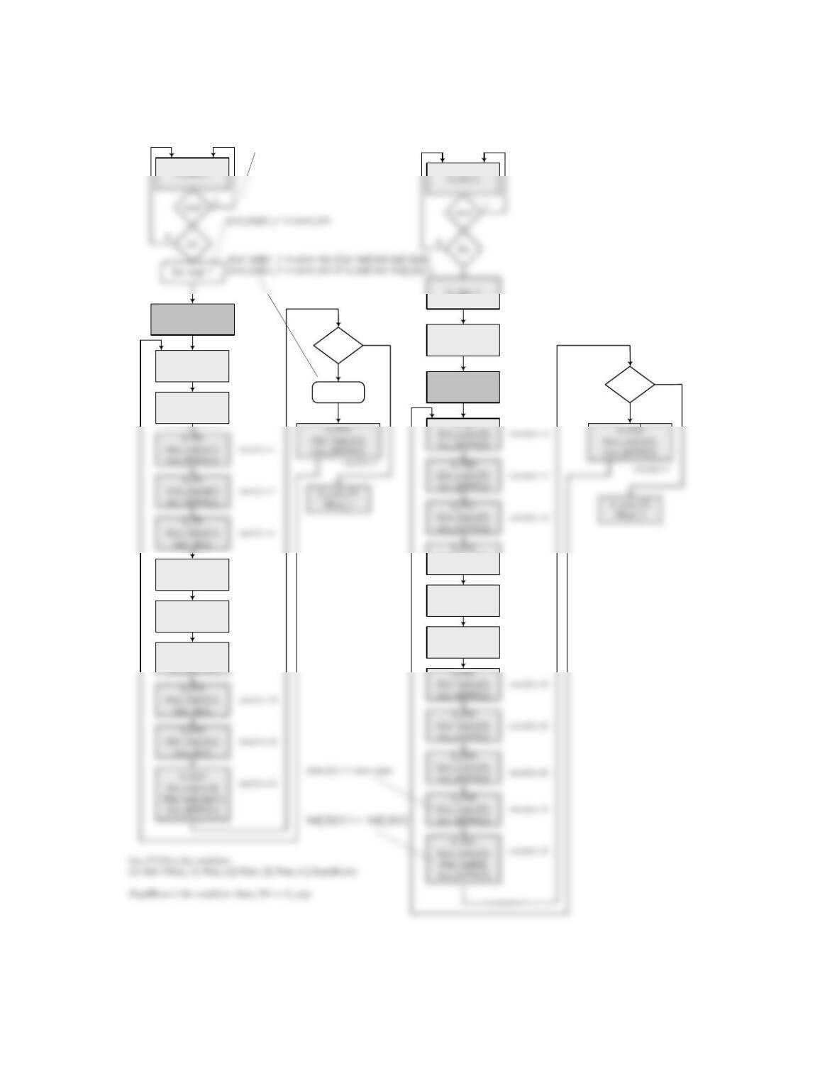
The block diagram of the concurrent processor is shown below.
• init_buff_1 establishes the initial values of index, pixel_buffer_1, pixel_buffer_2,
and buff_flg.
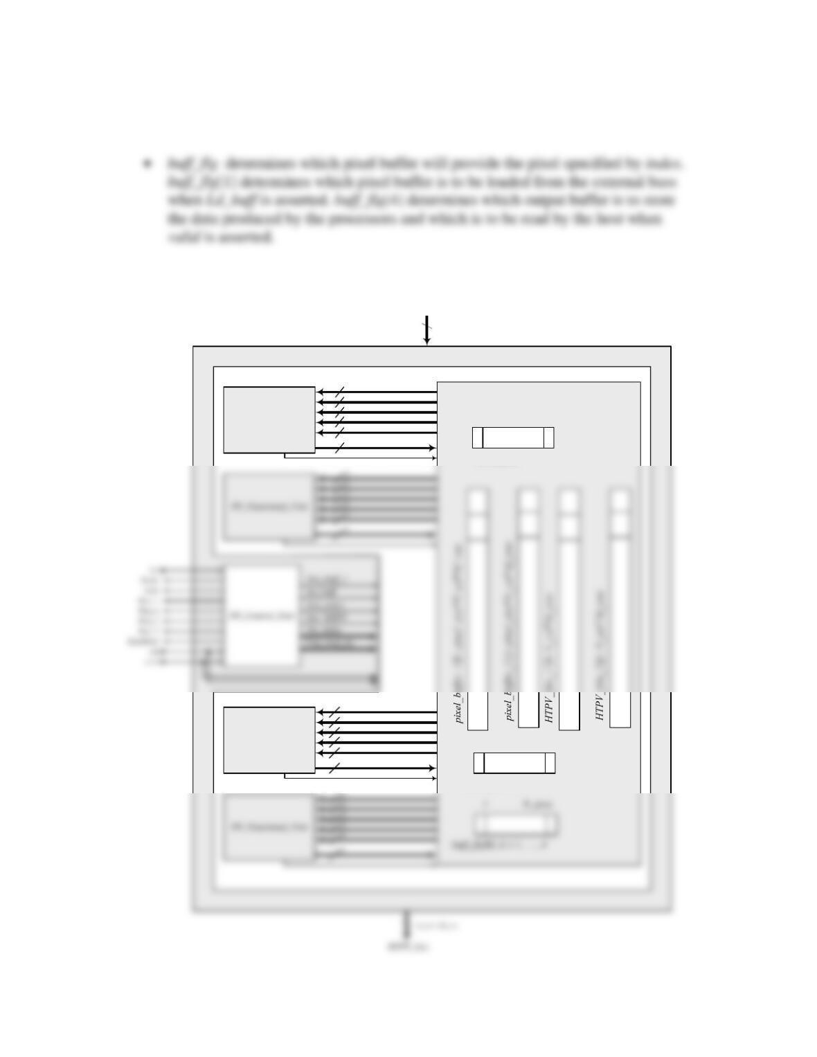
• Set_index loads index with the first processor to be processed by a given
processor
PP_Functional_Unit
PP_Functional_Unit
8
HTPV
8
8
8
8
8
PP_Memory_unit
index_size -1 0
index[k], k = 1, …, 4
Streaming_Image_Pixel_Processor
PP_1_Err_4
PP_1_PV
PP_1_Err_3
PP_1_Err_2
PP_1_Err_1
PP_1_Err_0
8
8
8
8
8
8
PP_Datapath_Unit
pixe;_size -1 0
Err[n][m]
pixel_bits
pixel_size x N_col x M_row

The interface signals have the following roles:
S_P1
/Get_index[1],
Get_HTPV[1]
pixel_buffer_1 <= 0
pixel_buffer_2 <= 0
buff_flg[k] <= 0, all k
index_[k] <= (k -1)*N_col +1
S_P2
/Get_index[1],
Get_HTPV[1]
S_P6
/Get_index[1],
Get_H[1]
S_P7
/Set_index[1],
Get_HTPV[1]
Ld_buff
0
Go_P1234
S_load
/Get_index[1],
Get_HTPV[1]
1
index[1] is 1
index[1] is 2
index[1] is 3
index[1] is 7
index[1] is 8
S_P9
/Get_index[2],
Get_HTPV[2]
Go_P1234
1
S_skip_2
S_skip_3
/Get_index[2],
Get_HTPV[2] index[2] is 9
index[2] is 13
S_P8
/Get_index[1]
index[1] is 15
S_skip_1
S_P13
/Get_index[2],
Get_HTPV[2]
index[2] is 14
S_P14
/Get_index[2],
Get_HTPV[2]
index[2] is 21
…
S_Skip_15
/Get_index[4],
Get_HTPV[4]
S_P25
/Get_index[4],
Get_HTPV[4]
S_wait_P4
/Valid
Wait_P4
index[4] is 25
index[4] is 26
S_idle_4
reset
1
S_P17
/Get_index[3]
Get_HTPV[3]
S_P18
/Get_index[3]
Get_HTPV[3]
S_wait_P3
/Wait_3
index[3] is 18
index[3] is 19
S_skip_8
/Get_index[3],
Get_HTPV[3] index[3] is 17
S_idle_3
reset
1
S_P19
/Get_index[3]
Get_HTPV[3]
index[3] is 20
S_P37
/Get_index[3]
Get_HTPV[3]
index[3] is 38
S_P38
/Get_index[3]
Get_HTPV[3]
index[3] is 39
S_skip_14
Get_HTPV[4]
S_P44
/Get_index[4],
Get_HTPV[4]
index[4] is 45
S_P45
/Get_index[4],
Get_HTPV[4]
index[4] is 46
S_P46
/Get_index[4],
Get_HTPV[4]
index[4] is 47
S_stop
/Stop4Reset,
Wait_4
Some simulation results are organized as shown in the next figures to expose the internal
behavior of the machine. The first figure shows the state of the machine and the control
signals following power-up reset. Notice that the evolution of the states of the four
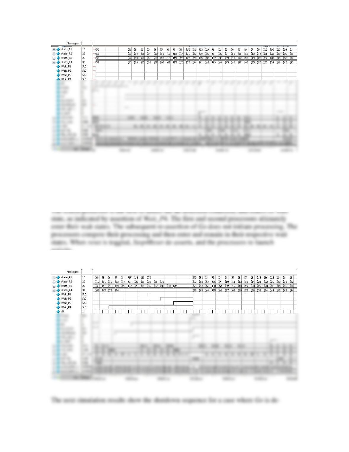
The simulation results below demonstrate how the machine behaves when Go is toggled
and interacts with reset. Notice that all four processors are active when Go is de-asserted.
activity.
asserted just before the fourth process is done. Valid asserts when the fourth processor
processes its last pixel. Wait_P4 asserts, and then the other three processors complete
their work. However, Valid is not re-asserted because only the values produced by the
first three processors are valid. The fourth processor did not complete the image.
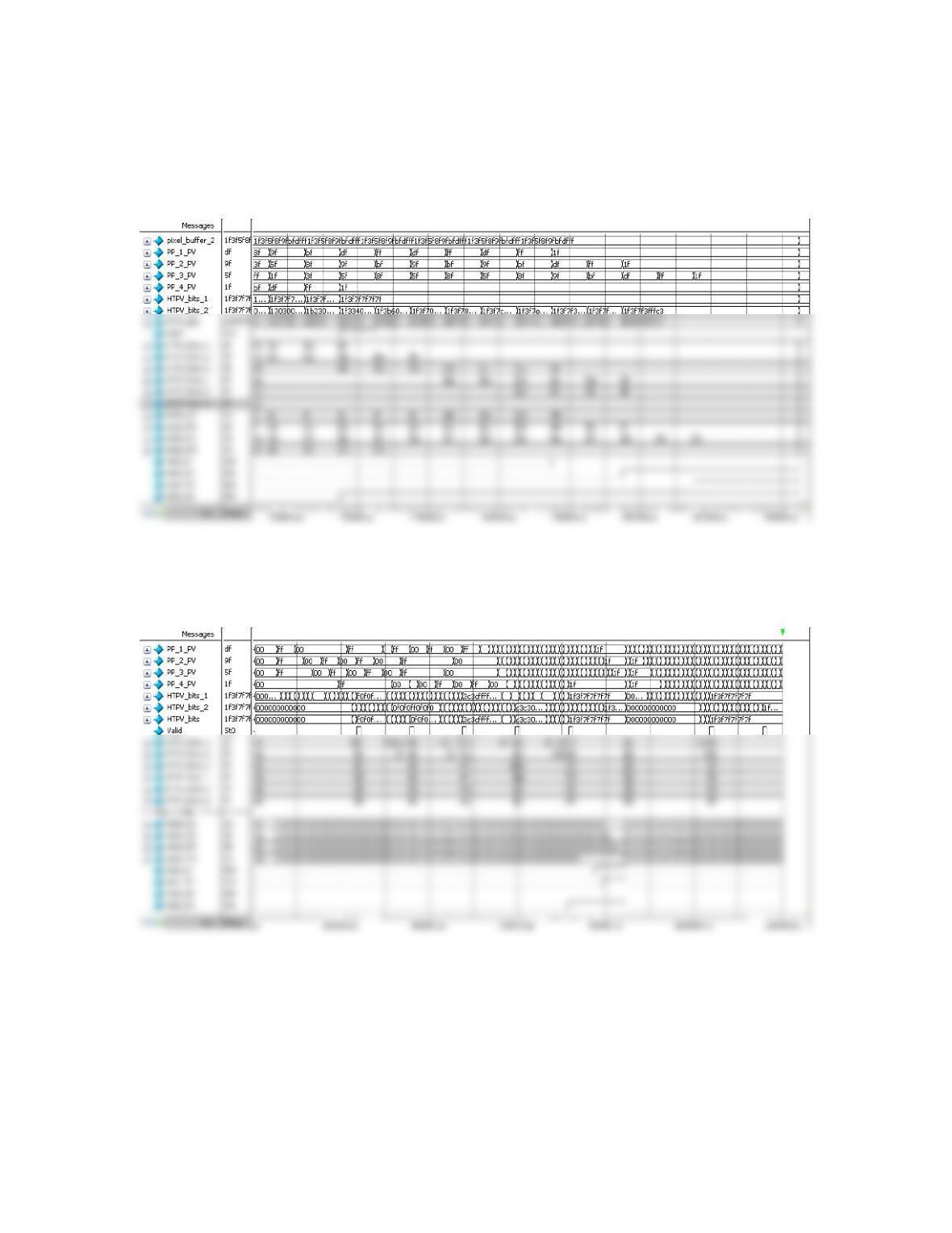
The next simulation results show the half-tone pixel values for five patterns. They match
the expected results for these patterns (see Problem 9-2.)

Problem 9-12
The synthesized Circular_Buffer_1 has a simpler hardware implementation that
Circular_Buffer_2. Also note that the reset action displayed in Figure 9.43 has a race
Problem 9-15
The two filters differ in the complexity of their interconnect fabric. The shift register has
a direct, parallel transfer of data through a shift register. The circular buffer must switch
the datapath between the registers and the multipliers, as determined by the specification
b0 = 8’d7, // Filter coefficients
b1 = 8’d17,
b2 = 8’d32,
b3 = 8’d46,
b4 = 8’d52,
b5 = 8’d46,
b6 = 8’d32,
b7 = 8’d17,
b8 = 8’d7)(
always @ (posedge clock)
if (reset == 1) begin for (k = 1; k <= FIR_order; k = k+1) Sample_Array[k] <= 0; end
else begin
Sample_Array [1] <= Data_in;
for (k = 2; k <= FIR_order; k = k+1) Sample_Array[k] <= Sample_Array[k-1];
end