Problem 9-2
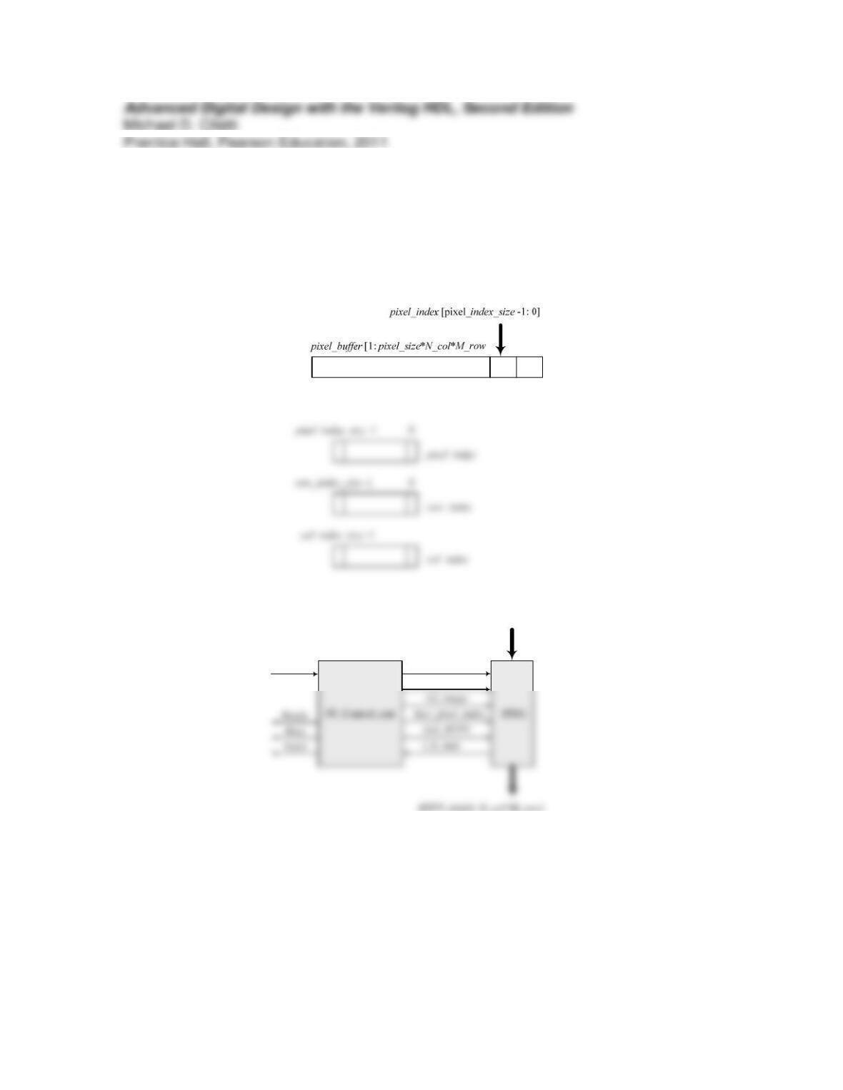
The figures below show (1) registers of the datapath unit of an implementation of a pixel
processor using a single processor, (2) a block diagram showing the interface signals
between the control unit and the datapath, and (3) the ASMD chart for the machine’s
Verilog model.
pixel_bits[1: pixel_size*N_col*M_row
Go
HTPV_bits[1: N_col*M_row]
Clr_buffer
Clr_pixel_index
`timescale 1ns /10ps
// For Xilinx synthesis:
wire Clr_buffer, Clr_pixel_index, Ld_image, Incr_pixel_index, Get_HTPV;
PP_Control_Unit M0
(Ready, Busy, Valid, Clr_buffer, Clr_pixel_index, Ld_image, Incr_pixel_index, Get_HTPV, Go,
i_lt_max, clk, reset);
PPDU M1
(HTPV_bits, i_lt_max, pixel_bits, Clr_buffer, Clr_pixel_index, Ld_image, Incr_pixel_index,
Get_HTPV, clk, reset);
endmodule
assign Ready = (state == S_idle);
assign Busy = (state == S_running);
assign Valid = (state == S_done);
always @ (posedge clk) if (reset) state <= S_idle; else state <= next_state;
// Pixel Processor Datapath Unit
module PPDU #(parameter
pixel_size = 8, pixel_index_size = 6, col_index_size = 4, row_index_size = 3,
Threshold = 128, w1 = 2, w2 = 8, w3 = 4, w4 = 2,
N_col = 8, M_row = 6
reg [pixel_index_size -1: 0] pixel_index;
reg [col_index_size -1: 0] col_index;
reg [row_index_size -1: 0] row_index;
integer n, m;
always
@ (posedge clk)
if (reset) begin: reset_action // Initialize borders of the array
for (n = 0; n <= N_col+1; n = n + 1) begin: top_border Err[n][0] = 1’b0; end
// Manage pointers
always @ (posedge clk)
if (reset) pixel_index <= 0;
else if (Clr_pixel_index) pixel_index <= 0;
else if (Incr_pixel_index) pixel_index <= pixel_index + 1;
1, 2, 3, 4, 5, 6, 7, 8: row_index = 1;
always @ (pixel_index) begin
col_index = 1;
case (pixel_index)
1, 9, 17, 25, 33, 41: col_index = 1;
2, 10, 18, 26, 34, 42: col_index = 2;
3, 11, 19, 27, 35, 43: col_index = 3;
always @ (pixel_index, pixel_buffer) begin
PV = pixel_buffer [(pixel_index -1)*pixel_size + 1 +: pixel_size];
/*
PV = 0;
case (pixel_index)
1: PV = pixel_buffer [1: pixel_size];
2: PV = pixel_buffer [pixel_size + 1: 2*pixel_size];
3: PV = pixel_buffer [2*pixel_size + 1: 3*pixel_size];
4: PV = pixel_buffer [3*pixel_size + 1: 4*pixel_size];
12: PV = pixel_buffer [11*pixel_size + 1: 12*pixel_size];
13: PV = pixel_buffer [12*pixel_size + 1: 13*pixel_size];
14: PV = pixel_buffer [13*pixel_size + 1: 14*pixel_size];
15: PV = pixel_buffer [14*pixel_size + 1: 15*pixel_size];
16: PV = pixel_buffer [15*pixel_size + 1: 16*pixel_size];
17: PV = pixel_buffer [16*pixel_size + 1: 17*pixel_size];
26: PV = pixel_buffer [25*pixel_size + 1: 26*pixel_size];
27: PV = pixel_buffer [26*pixel_size + 1: 27*pixel_size];
28: PV = pixel_buffer [27*pixel_size + 1: 28*pixel_size];
29: PV = pixel_buffer [28*pixel_size + 1: 29*pixel_size];
30: PV = pixel_buffer [29*pixel_size + 1: 30*pixel_size];
31: PV = pixel_buffer [30*pixel_size + 1: 31*pixel_size];
*/
end
endmodule
module t_Image_Converter_Single_Processor # (parameter
pixel_size = 8, N_col = 8, M_row = 6)();
wire [1: N_col*M_row] HTPV_bits;
wire Ready, Busy, Valid;
reg [1: pixel_size * N_col * M_row] pixel_bits;
reg Go, clk, reset;
wire [1: N_col] HTPV_Row_1, HTPV_Row_2, HTPV_Row_3;
wire [1: N_col] HTPV_Row_4, HTPV_Row_5, HTPV_Row_6;
initial #4000 $finish;
initial begin clk = 0; forever #5 clk = ~clk; end
initial fork
reset = 1; #10 reset = 0;
#50 Go = 1;
//#60 Go = 0;
join
// Instantiate Image_Converter_Single_Processor
Image_Converter_Single_Processor M0 (HTPV_bits, Ready, Busy, Valid, pixel_bits, Go, clk,
reset);
initial begin
// Image_Pattern_2
@ (posedge (M0.M0.state == M0.M0.S_done))
pixel_bits = { 8’h00, 8’h00, 8’h00, 8’h00, 8’hff, 8’hff, 8’hff, 8’hff,
// Image_Pattern_3_Cross
@ (posedge (M0.M0.state == M0.M0.S_done))
pixel_bits = { 8’h00, 8’h00, 8’hff, 8’hff, 8’hff, 8’hff, 8’h00, 8’h0,
8’h00, 8’h00, 8’hff, 8’hff, 8’hff, 8’hff, 8’h00, 8’h00,
8’hff, 8’hff, 8’hff, 8’hff, 8’hff, 8’hff, 8’hff, 8’hff,
8’hff, 8’hff, 8’hff, 8’hff, 8’hff, 8’hff, 8’hff, 8’hff,
8’h00, 8’h00, 8’hff, 8’hff, 8’hff, 8’hff, 8’h00, 8’h0,
8’h00, 8’h00, 8’hff, 8’hff, 8’hff, 8’hff, 8’h00, 8’h0};
// Image_Pattern_5_Graduated_Left_to_Right
@ (posedge (M0.M0.state == M0.M0.S_done))
pixel_bits = { 8’h1f, 8’h3f, 8’h5f, 8’h8f, 8’h9f, 8’hbf, 8’hdf, 8’hff,
8’h1f, 8’h3f, 8’h5f, 8’h8f, 8’h9f, 8’hbf, 8’hdf, 8’hff,
8’h1f, 8’h3f, 8’h5f, 8’h8f, 8’h9f, 8’hbf, 8’hdf, 8’hff,
8’h1f, 8’h3f, 8’h5f, 8’h8f, 8’h9f, 8’hbf, 8’hdf, 8’hff,
8’h1f, 8’h3f, 8’h5f, 8’h8f, 8’h9f, 8’hbf, 8’hdf, 8’hff,
8’h1f, 8’h3f, 8’h5f, 8’h8f, 8’h9f, 8’hbf, 8’hdf, 8’hff};
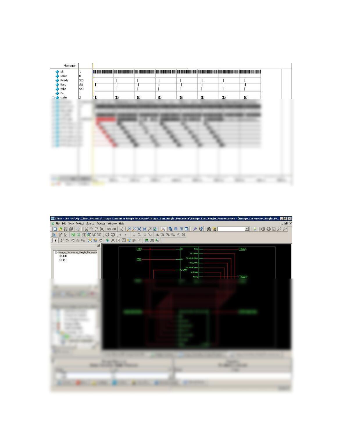
The simulation results below produce the same halftone images as the machines in
Chapter 9.
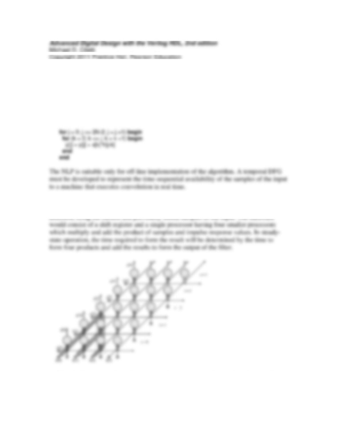
The RTL schematic produced by the Xilinx ISE 10.1 synthesis tools is shown below;
additional details are left to the student.
Problem 9-3
(a) A Verilog module to accept a sample sequence and produce a sequence of outputs is
given below:
y[0] = x[0]h[0]
y[1] = x[0]h[1] + x[1]h[0]
y[2] = x[0]h[2] + x[1]h[1] + x[2]h[0]
(b) Temporal DFG for N = 4 is shown below, with shading to identify the data used to
form y[2]. The computation sequence can be viewed as proceeding in the vertical
(c) The Verilog model of the filter samples the input at each clock and implements the
nested loop structure of the algorithm. The samples of the input are shifted through a shift
register. At each time step, the sample values are multiplied by the appropriate value of
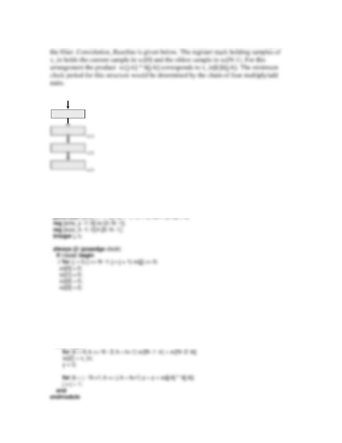
the impulse response of the filter, and the results are added to form the current output of
x_in
xc[0]
module Convolution_Baseline #(parameter N = 4, size_y = 6, size_x = 4, size_h = 4)(
output reg [size_y -1: 0] y,
input [size_x -1: 0] x_in,
input clock, reset
);
h[0] = h0;
h[1] = h1;
h[2] = h2;
h[3] = h3;
j = 0;
y = 0;
end
else begin
module t_Convolution_Baseline #(parameter N = 4, size_y = 6, size_x = 4)();
wire [size_y -1: 0] y;
reg [size_x -1: 0] x_in;
reg clock, reset;
Convolution_Baseline M0 (y, x_in,clock, reset);
initial #500 $finish;
initial begin clock = 0; forever #5 clock = ~clock; end
endmodule
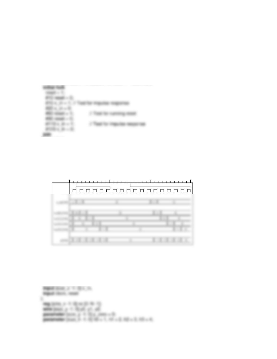
The impulse response of a finite duration impulse response discrete-time filter is the
sequence of its filter coefficients: h[0], h[1], h[2], h[3], …, as shown below for
Convolution_Baseline. The simulation results also recovery from a running reset.
Name 060 120 180
reset
clock
t
For comparison, a structural model of the filter is given below. Its response matches that
of the NLP-based behavioral model.
module Convolution_Baseline_STR # (parameter N = 4, size_y = 6, size_x = 4, size_h = 4)(
output [size_y -1: 0] y,
integer k;
always @ (posedge clock)
if (reset) begin
// for (j = 1; j <= N -1; j = j + 1) xc[j] <= 0;
xc[0] = 0;
xc[1] = 0;
module Processor # (parameter size_y = 6, size_x = 4, size_h = 4)(
output [size_y -1: 0] y_out_value,
input [size_x -1: 0] x_sample,
input [size_y -1: 0] y_in_value,
input [size_h -1: 0] h_value
);
assign y_out_value = y_in_value + h_value * x_sample;
endmodule
initial #500 $finish;
initial begin clock = 0; forever #5 clock = ~clock; end
initial fork
reset = 1;
#10 reset = 0;
#10 x_in = 1; // Test for impulse response
Name 060 120 180
reset
clock
t
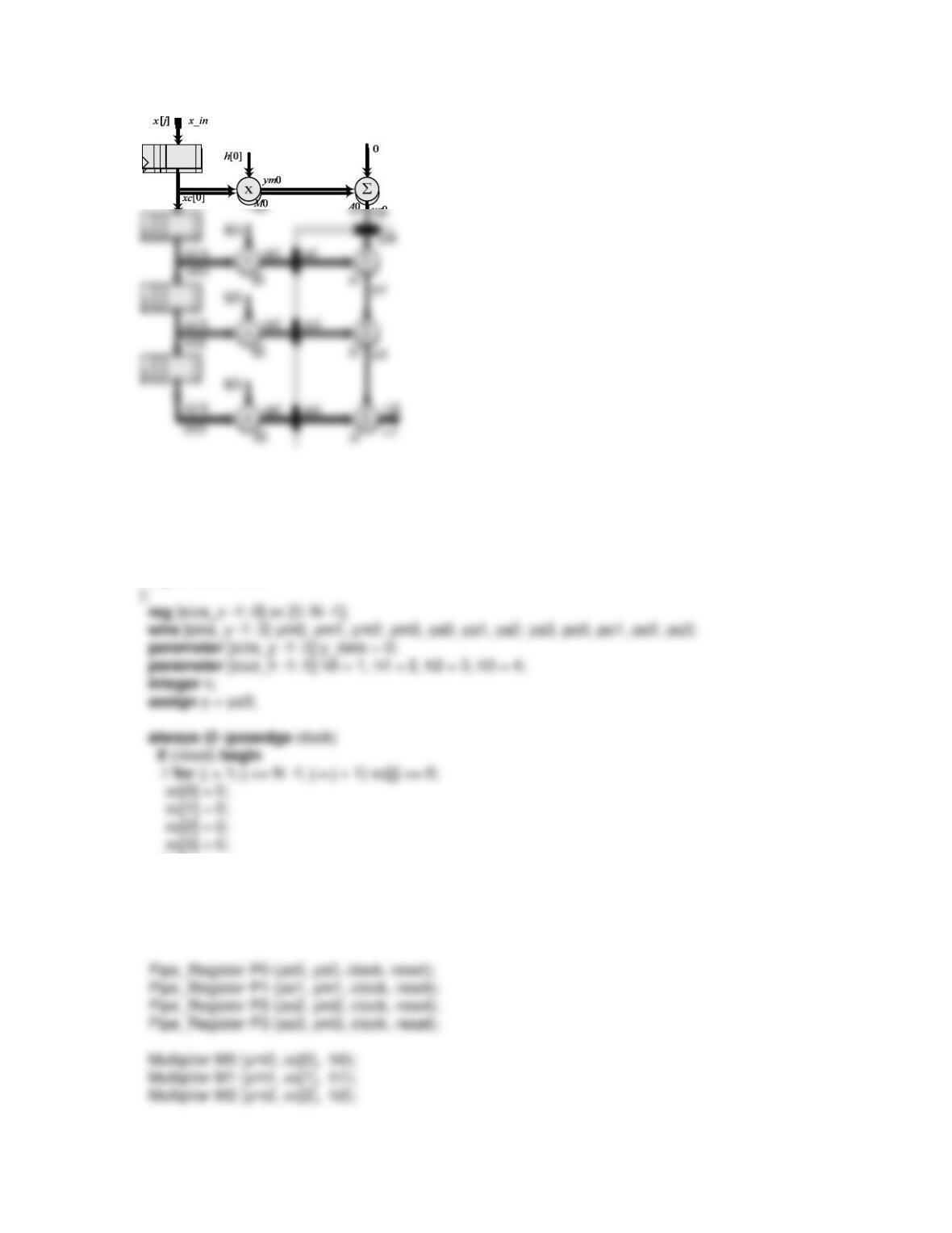
(d) Pipeline registers and a cutset based on Figure 9-41(a)) are shown below. This
structure places the operations of multiplication and addition in adjacent clock cycles.
Whether it is actually balanced or not depends on the time for multiplication versus the
time delay required for addition. This must be tested for a physical realization.
h[0]
0
x[j]
x
Pipeline
register
Cutset
boundary
Pipeline
Stage
h[0]
0
x
x[j]
ym0
xc[0]
x_in
(e) The Verilog model of the alternative pipelined structure is given below.
module Convolution_Pipeline_STR # (parameter N = 4, size_y = 6, size_x = 4, size_h = 4)(
output [size_y -1: 0] y,
input [size_x -1: 0] x_in,
input clock, reset
end
else begin
for (k = 0; k <= N-1; k = k+1) xc[k + 1] <= xc[k]; // Load shift register
xc[0] = x_in;
end
Multiplier M3 (ym3, xc[3], h3);
Adder A0 (ya0, ym0, y_zero);
);
always @ (posedge clock)
if (reset) pipe_out <= 0; else pipe_out <= pipe_in;
endmodule
module Multiplier # (parameter size_y = 6, size_x = 4, size_h = 4)(
output [size_y -1: 0] y_out_value,
module Adder # (parameter size_y = 6)(
output [size_y -1: 0] y_out_value,
input [size_y -1: 0] y_prod,
input [size_y -1: 0] y_in_value
);
assign y_out_value = y_in_value + y_prod;
endmodule
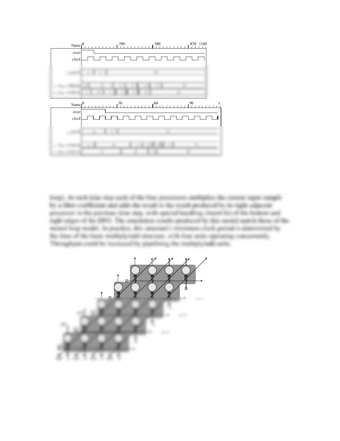
The simulation result below show the outputs of the baseline structural model and the
pipelined structural model, simulated with 5 units of delay for the multiplier and 2 units
(f) The temporal DFG below indicates that the minimum number of concurrent
processors is 4. An alternative Verilog behavioral model (Concurrent_Convolution) is
based on the temporal DFG and has four concurrent processors (the result of unrolling the
y[2]
x[3]
y[3]
y[4]
x[4]
0
module Concurrent_Convolution #(parameter N = 4, size_y = 6, size_x = 4)(
output [size_y -1: 0] y,
input [size_x -1: 0] x_in,
input clock, reset
always @ (posedge clock)
if (reset) begin
// for (j = 1; j <= N -1; j = j + 1) xc[j] <= 0;
xc[3] = 0;
xc[2] = 0;
xc[1] = 0;
xc[0] = 0;
Problem 9-5
module Bubble_Sort_Alternative # ( parameter N = 8, word_size = 4)(
output [word_size -1: 0] Data_out,
output Ready, Busy, Waiting,
input [word_size -1: 0] Data_in,
input Load, Sort, Send, clk, rst
);
);
endmodule
module Controller (
output Ready, Busy, Waiting,
output reg ld, set_i, incr_i, set_j, decr_j, clr_k, incr_k, swap, snd,
input Load, Sort, Send, gt, i_lte_N, j_gte_i, done, clk, rst
);
always @ (state, Load, Sort, Send, gt, i_lte_N, j_gte_i, done ) begin
next_state = S_rst;
ld = 0;
set_i = 0; incr_i = 0;
set_j = 0; decr_j = 0;
clr_k = 0; incr_k = 0;
else begin next_state = S_send; swap = 1; incr_k = 1; end
end
default: next_state = S_rst;
endcase
end
endmodule
assign Data_out = A[N];
assign done = (k == N-1);
assign gt = (A[j-1] > A[j]); // compares words
assign i_lte_N = (i <= N);
assign j_gte_i = (i <= j);
always @ (posedge clk) // Datapath and pointers
if (rst) begin i <= 0; j <= 0; end
module t_Bubble_Sort ();
parameter word_size = 4;
wire [word_size -1: 0] Data_out;
wire Ready, Busy, Waiting;
reg Load, Sort, Send, clk, rst;
reg [word_size -1: 0] Data_in;
wire [word_size -1: 0] A1, A2, A3, A4, A5, A6, A7, A8;
Bubble_Sort_Alternative M0 (Data_out, Ready, Busy, Waiting, Data_in, Load, Sort, Send, clk,
rst);
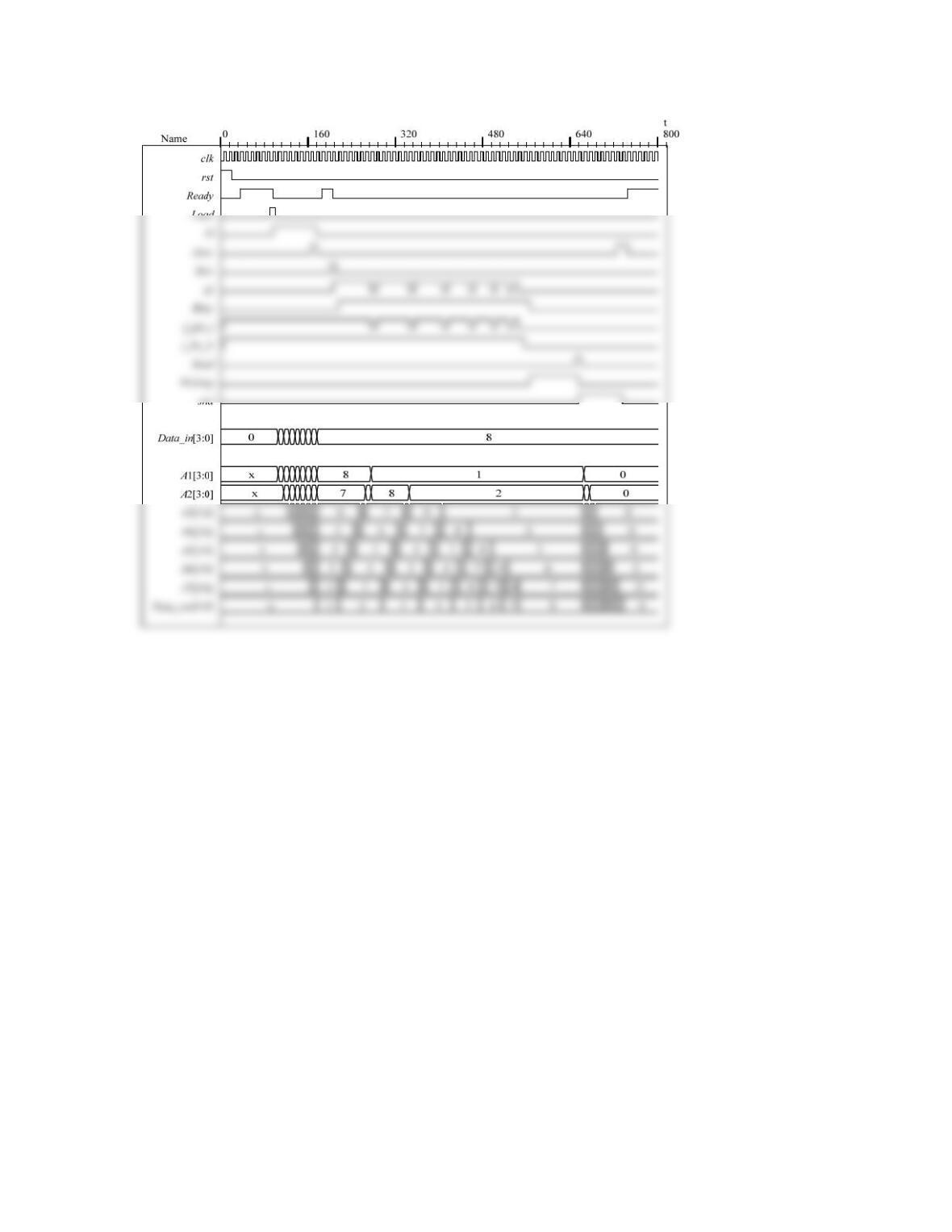
initial #800 $finish;
initial begin clk = 0; forever #5 clk = ~clk; end
initial fork
rst = 1; Load = 0; Sort = 0; Send = 0;
#20 rst = 0; //#450 rst = 1; #470 rst = 0; // Remove // to test reset on-the-fly
Data_in = 8’h0;
#90 Load = 1;
#100 Load = 0;
#200 Sort = 1;