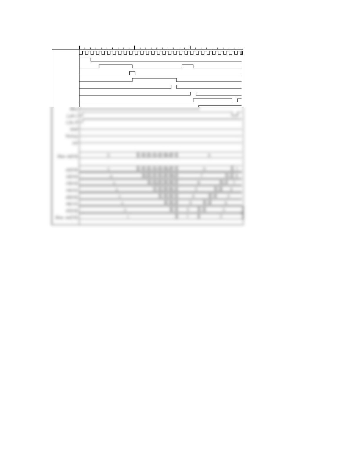
Name
clk
rst
Ready
Load
ld
done
Sort
gt
0100 200 t
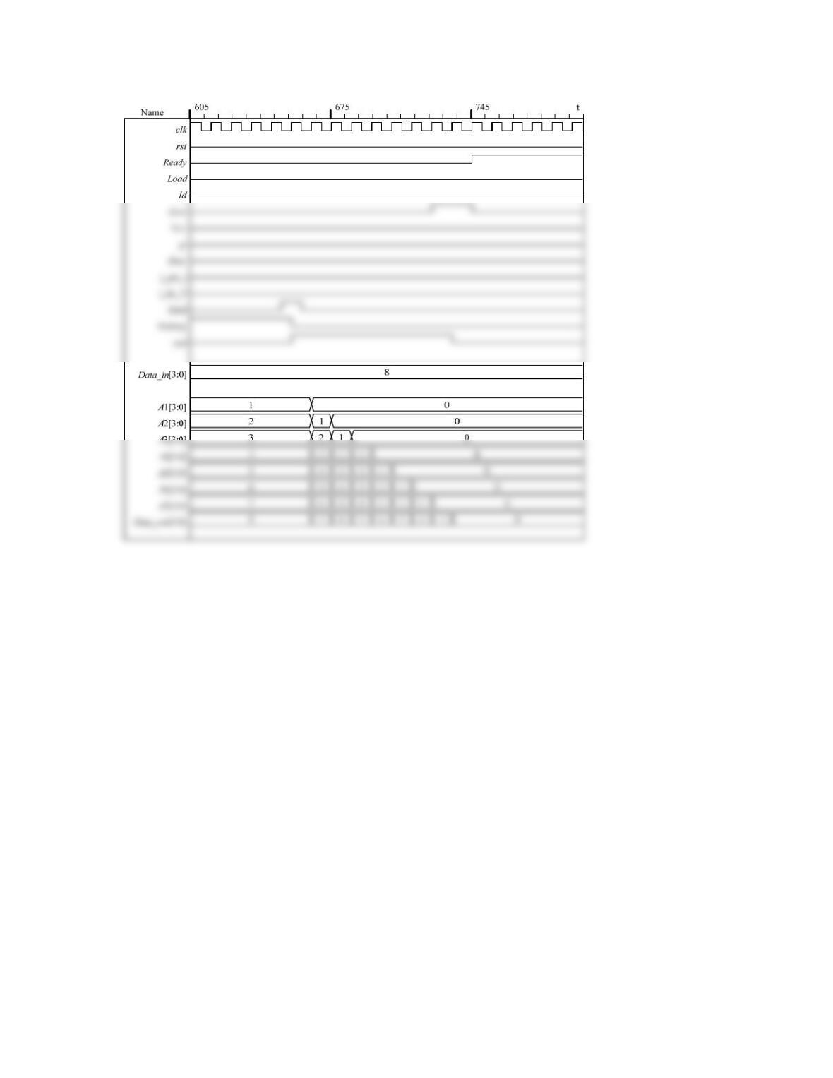
Problem 9-6 (a)
The presentation in Section 9.2 converted an 8-bit pixel value into a one-bit halftone
value. In this problem, the 8-bit pixel value is to be mapped into a 4-bit value. Applying
the Floyd-Steinberg algorithm gives the same data flow graph (see Figure 9-5). The key
change is to the calculation of the adjusted (rounded) corrected pixel value. Instead of a
// Isomorphic array of processors
module Image_Converter_Baseline_GRAY4 # (
parameter pixel_size = 8, N_col = 8, M_row = 6, GS_size = 4)(
output [1: GS_size* N_col*M_row] GSPV_bits,
input [1: pixel_size * N_col * M_row] pixel_bits
// Instantiate array of pixel processors
for (m = 1; m <= M_row; m = m + 1) begin: row_loop
for (n = 1; n <= N_col; n = n + 1) begin: column_loop
PPDU M (Err[n][m], GSPV[n][m], Err[n -1][m], Err[n -1][m -1], Err[n][m -1], Err[n +
1][m -1],
pixel_bits[(m -1)*N_col*pixel_size +(n -1)*pixel_size +1: (m -1)*N_col*pixel_size +
n*pixel_size]);
end
end
endgenerate
endmodule
// Pixel Processor Datapath Unit
// Weights for the average error; choose for compatibility with divide-by-16 (>> 4)
parameter w1 = 2, w2 = 8, w3 = 4, w4 = 2;
always @ (CPV) begin
CPV_round = 255; GSPV = 4’b1111;
if ((0 <= CPV) && (CPV < T0)) begin CPV_round = 0; GSPV = 4’b0000; end else
if ((T0 <= CPV) && ( CPV < T1)) begin CPV_round = 16; GSPV = 4’b0001; end else
if ((T1 <= CPV) && (CPV < T2)) begin CPV_round = 32; GSPV = 4’b0010; end else
if ((T2 <= CPV) && (CPV < T3)) begin CPV_round = 48; GSPV = 4’b0011; end else
if ((T3 <= CPV) && (CPV < T4)) begin CPV_round = 64; GSPV = 4’b0100; end else
end
assign Err_0 = CPV – CPV_round;
endmodule
wire [GS_size * N_col -1: 0] GSPV_Row_1;
wire [GS_size * N_col -1: 0] GSPV_Row_2;
// wire [GS_size -1: 0] GSPV_Row_1[1: GS_size * N_col];
reg [1: pixel_size*N_col*M_row] pixel_bits;
wire [1: GS_size*N_col*M_row] GSPV_bits;
reg [GS_size -1: 0] GSPV [1: N_col][1: M_row];
integer n, m;
assign GSPV_Row_1 = GSPV_bits[1: GS_size * N_col];
assign GSPV_Row_2 = GSPV_bits[1 + GS_size*N_col: 2*GS_size*N_col];
Image_Converter_Baseline_GRAY4 M1 (GSPV_bits, pixel_bits); // Instantiate image
converter
initial fork
begin: Image_Pattern_1
pixel_bits = { 8’hff, 8’hff, 8’hff, 8’hff, 8’h00, 8’h00, 8’h00, 8’h00,
8’hff, 8’hff, 8’hff, 8’hff, 8’h00, 8’h00, 8’h00, 8’h00,
8’hff, 8’hff, 8’hff, 8’hff, 8’h00, 8’h00, 8’h00, 8’h00,
8’hff, 8’hff, 8’hff, 8’hff, 8’h00, 8’h00, 8’h00, 8’h00};
end
#1000 begin: Image_Pattern_3_Cross
pixel_bits = { 8’h00, 8’h00, 8’hff, 8’hff, 8’hff, 8’hff, 8’h00, 8’h0,
end
#1500 begin: Image_Pattern_4_Bar_Cross
pixel_bits = { 8’hff, 8’hff, 8’h00, 8’h00, 8’h00, 8’h00, 8’hff, 8’hff,
end
#2500 begin: Image_Pattern_6_Mixed_Values
pixel_bits = { 8’h1f, 8’h3f, 8’h5f, 8’h8f, 8’h9f, 8’hbf, 8’hdf, 8’hff,
8’h1f, 8’h3f, 8’h5f, 8’h8f, 8’h9f, 8’hbf, 8’hdf, 8’hff,
8’h1f, 8’h3f, 8’h5f, 8’h8f, 8’h9f, 8’hbf, 8’hdf, 8’hff,
Problem 9-6 (b)
Four processors provide maximally concurrent processing. The machine is based on
Figure 9-12, with the source code given below.
// Array of concurrent processors
module Image_Converter_Concurrent_Processors_GRAY4 # (
parameter pixel_size = 8, N_col = 8, M_row = 6, GS_size = 4)(
output [1: GS_size* N_col*M_row] GSPV_bits,
wire [pixel_size -1: 0] PP_1_PV, PP_2_PV, PP_3_PV, PP_4_PV;
wire [GS_size -1: 0] PP_1_GSPV, PP_2_GSPV, PP_3_GSPV, PP_4_GSPV;
// Instantiate Pixel Processor Datapath Units Control Unit, Memory Unit
PPDU M1 (PP_1_Err_0, PP_1_GSPV, PP_1_Err_1, PP_1_Err_2, PP_1_Err_3,
PP_1_Err_4, PP_1_PV);
PP_Memory_Unit M5 (
GSPV_bits,
PP_1_Err_1, PP_1_Err_2, PP_1_Err_3, PP_1_Err_4, PP_1_PV,
PP_2_Err_1, PP_2_Err_2, PP_2_Err_3, PP_2_Err_4, PP_2_PV,
PP_3_Err_1, PP_3_Err_2, PP_3_Err_3, PP_3_Err_4, PP_3_PV,
PP_4_Err_1, PP_4_Err_2, PP_4_Err_3, PP_4_Err_4, PP_4_PV,
pixel_bits, index, Go, Ld_image, Ld_values, clk, reset
);
endmodule
module PP_Control_Unit (output reg [23: 0] index, output reg Ld_image, Ld_values, Done,
input Go, clk, reset);
reg [4: 0] state, next_state;
parameter
S_idle = 5’d0, S_1 = 5’d1, S_2 = 5’d2, S_3 = 5’d3, S_4 = 5’d4, S_5 = 5’d5, S_6 = 5’d6,
always @ (state, Go) begin
Done = 0;
Ld_image = 0;
if (state == S_idle) begin Done = 1; if (Go) Ld_image = 1; end
end
always @ (state) begin
index = 0;
case (state)
S_idle: index = {{6’d0}, {6’d0}, {6’d0}, {6’d0}};
S_1: index = {{6’d1}, {6’d0}, {6’d0}, {6’d0}};
S_2: index = {{6’d2}, {6’d0}, {6’d0}, {6’d0}};
S_10: index = {{6’d16}, {6’d22}, {6’d28}, {6’d34}};
S_11: index = {{6’d23}, {6’d29}, {6’d35}, {6’d41}};
S_12: index = {{6’d24}, {6’d30}, {6’d36}, {6’d42}};
S_13: index = {{6’d0}, {6’d31}, {6’d37}, {6’d43}};
// Pixel Processor Datapath Unit
module PPDU #(parameter pixel_size = 8, GS_size = 4)(
// Weights for the average error; choose for compatibility with divide-by-16 (>> 4)
parameter w1 = 2, w2 = 8, w3 = 4, w4 = 2;
parameter T0 = 16, T1 = 32, T2 = 48, T3 = 64;
always @ (CPV) begin
CPV_round = 255; GSPV = 4’b1111;
if ((0 <= CPV) && (CPV < T0)) begin CPV_round = 0; GSPV = 4’b0000; end else
if ((T0 <= CPV) && ( CPV < T1)) begin CPV_round = 16; GSPV = 4’b0001; end else
if ((T1 <= CPV) && (CPV < T2)) begin CPV_round = 32; GSPV = 4’b0010; end else
if ((T2 <= CPV) && (CPV < T3)) begin CPV_round = 48; GSPV = 4’b0011; end else
end
assign Err_0 = CPV – CPV_round;
endmodule
module PP_Memory_Unit # (parameter pixel_size = 8, N_col = 8, M_row = 6, GS_size = 4)(
output [1: GS_size*N_col*M_row] GSPV_bits,
output reg [pixel_size: 0] PP_1_Err_1, PP_1_Err_2, PP_1_Err_3, PP_1_Err_4,
output reg [pixel_size -1: 0] PP_1_PV,
input Go, Ld_image, Ld_values, clk, reset
);
// Array of pixel data
reg [pixel_size -1: 0] PV [1: N_col][1: M_row];
// Form output vector of output Grayscale values
generate
for (mm = 1; mm <= M_row; mm = mm + 1) begin: GSPV_row_loop
for (nn = 1; nn <= N_col; nn = nn + 1) begin: GSPV_col_loop
assign GSPV_bits [(mm -1)*N_col*GS_size + (nn-1)*GS_size +1: (mm –
1)*N_col*GS_size + nn*GS_size] = GSPV[nn][mm]; // Accomodates word packing
always @ (index_1) begin
case (index_1)
1, 2, 3, 4, 5, 6, 7, 8: begin PP_1_Err_1 = Err [index_1 -1][1];
PP_1_Err_2 = Err [index_1 -1][0];
PP_1_Err_3 = Err [index_1][0];
PP_1_Err_4 = Err [index_1 +1][0];
PP_1_PV = PV [index_1][1];
end
15, 16: begin
PP_1_Err_1 = Err [index_1 -1 -8][2];
PP_1_Err_2 = Err [index_1 -1 -8][1];
PP_1_Err_3 = Err [index_1 -8][1];
PP_1_Err_4 = Err [index_1 +1 -8][1];
PP_1_PV = PV [index_1 -8][2];
always @ (index_2) begin
case (index_2)
9, 10, 11, 12, 13, 14: begin
PP_2_Err_1 = Err [index_2 -1 -8][2];
PP_2_Err_2 = Err [index_2 -1 -8][1];
PP_2_Err_3 = Err [index_2 -8][1];
PP_2_Err_4 = Err [index_2 +1-8][1];
PP_2_PV = PV [index_2 -8][2];
end
21, 22: begin
default: begin
PP_2_Err_1 = 8’bx; PP_2_Err_2 = 8’bx; PP_2_Err_3 = 8’bx;
PP_2_Err_4 = 8’bx; PP_2_PV = 8’bx;
end
endcase
end
PP_3_PV = PV [index_3 -16][3];
end
27, 28: begin
PP_3_Err_1 = Err [index_3 -1 -24][4];
PP_3_Err_2 = Err [index_3 -1 -24][3];
PP_3_Err_3 = Err [index_3 -24][3];
PP_3_Err_4 = Err [index_3 +1 -24][3];
PP_3_PV = PV[index_3 -24][4];
end
endcase
end
always @ (index_4) begin
case (index_4)
25, 26: begin
PP_4_Err_1 = Err [index_4 -1 -24][4];
PP_4_Err_2 = Err [index_4 -1 -24][3];
PP_4_Err_3 = Err [index_4 -24][3];
PP_4_Err_4 = Err [index_4 +1 -24][3];
PP_4_PV = PV [index_4 -24][4];
end
default: begin
PP_4_Err_1 = 8’bx; PP_4_Err_2 = 8’bx; PP_4_Err_3 = 8’bx;
PP_4_Err_4 = 8’bx; PP_4_PV = 8’bx;
end
endcase
end
// Synchronous Behavior
integer n, m;
else if (Ld_image) begin: Array_Initialization
for (m = 1; m <= M_row; m = m +1) begin: row_loop
for (n = 1; n <= N_col; n = n +1) begin: col_loop
Err [n][m] <= 0; // Note part-select (+:) in next line to form range
PV [n][m] <= pixel_bits[(m -1)*N_col*pixel_size + (n -1)*pixel_size +1 +: pixel_size];
15, 16: begin
Err [index_1 -8][2] <= PP_1_Err_0;
GSPV [index_1 -8][2] <= PP_1_GSPV; end
23, 24: begin
Err [index_1 -16][3] <= PP_1_Err_0;
GSPV [index_1 -16][3] <= PP_1_GSPV; end
endcase
case (index_3)
17, 18, 19, 20: begin
endcase
case (index_4)
25, 26: begin
Err [index_4 – 24][4] <= PP_4_Err_0;
GSPV [index_4 -24][4] <= PP_4_GSPV; end
33, 34: begin
Err [index_4 -32][5] <= PP_4_Err_0;
GSPV [index_4 -32][5] <= PP_4_GSPV;end
wire [GS_size * N_col -1: 0] GSPV_Row_1;
wire [GS_size * N_col -1: 0] GSPV_Row_2;
wire [GS_size * N_col -1: 0] GSPV_Row_3;
wire [GS_size * N_col -1: 0] GSPV_Row_4;
wire [GS_size * N_col -1: 0] GSPV_Row_5;
wire [GS_size * N_col -1: 0] GSPV_Row_6;
// Form array of grayscale values
always @ (GSPV_bits) begin
for (m = 1; m <= M_row; m = m + 1)
for (n = 1; n <= N_col; n = n + 1)
GSPV [n][m] = GSPV_bits [ (m-1)*N_col + n +: GS_size ];
end
Image_Converter_Concurrent_Processors_GRAY4 M1 (GSPV_bits, Done, pixel_bits, Go,
clk, reset);
initial fork
begin: Image_Pattern_1
pixel_bits = { 8’hff, 8’hff, 8’hff, 8’hff, 8’h00, 8’h00, 8’h00, 8’h00,
8’hff, 8’hff, 8’hff, 8’hff, 8’h00, 8’h00, 8’h00, 8’h00,
8’hff, 8’hff, 8’hff, 8’hff, 8’h00, 8’h00, 8’h00, 8’h00,
8’h00, 8’h00, 8’h00, 8’h00, 8’hff, 8’hff, 8’hff, 8’hff,
8’h00, 8’h00, 8’h00, 8’h00, 8’hff, 8’hff, 8’hff, 8’hff,
8’h00, 8’h00, 8’h00, 8’h00, 8’hff, 8’hff, 8’hff, 8’hff};
end
#1500 begin: Image_Pattern_4_Bar_Cross
pixel_bits = { 8’hff, 8’hff, 8’h00, 8’h00, 8’h00, 8’h00, 8’hff, 8’hff,
8’hff, 8’hff, 8’h00, 8’h00, 8’h00, 8’h00, 8’hff, 8’hff,
8’h00, 8’h00, 8’h00, 8’h00, 8’h00, 8′h00, 8’h00, 8’h00,
8’h00, 8’h00, 8’h00, 8’h00, 8’h00, 8′h00, 8’h00, 8’h00,
8’hff, 8’hff, 8’h00, 8’h00, 8’h00, 8’h00, 8’hff, 8’hff,
8’hff, 8’hff, 8’h00, 8’h00, 8’h00, 8’h00, 8’hff, 8’hff};
end
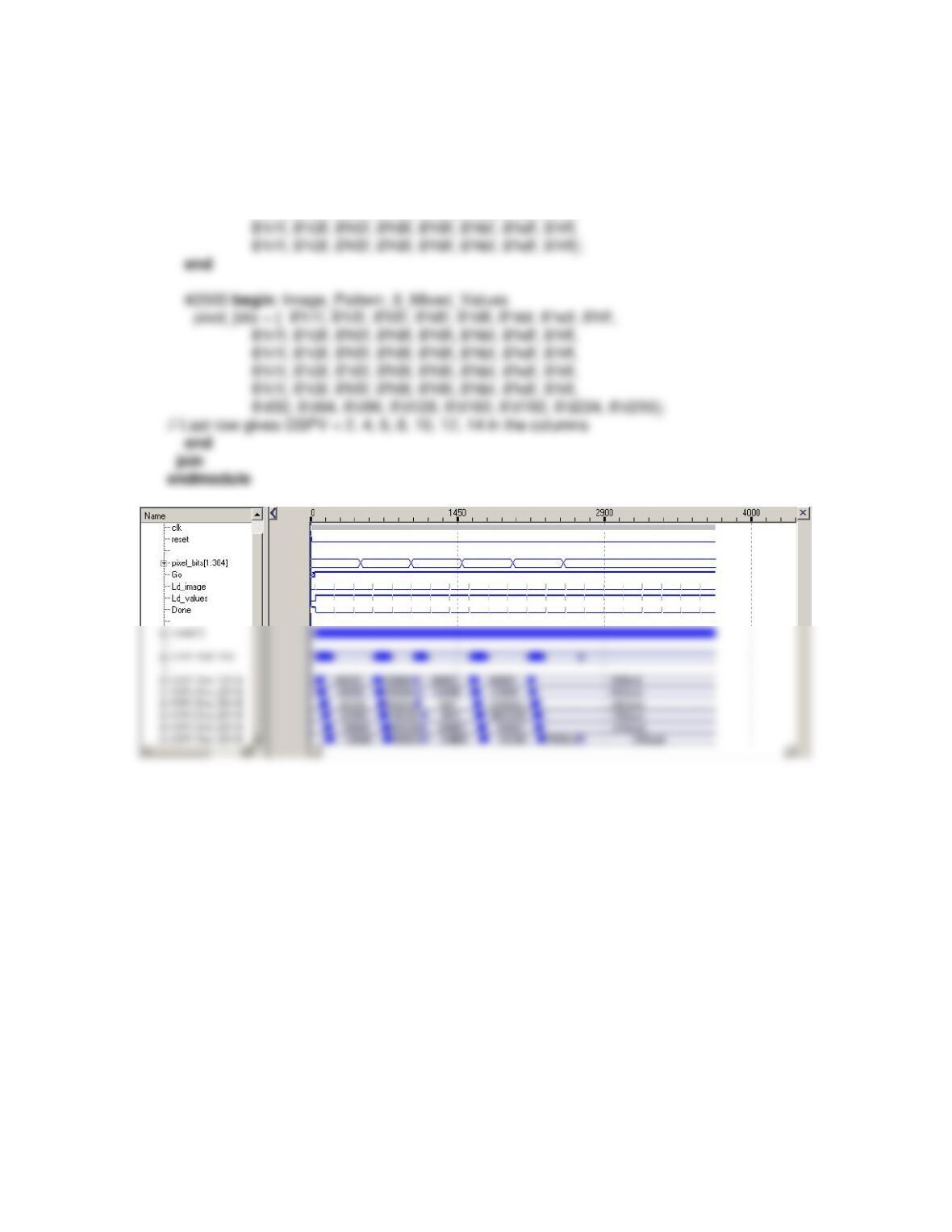
#2000 begin: Image_Pattern_5_Graduated_Left_to_Right
pixel_bits = { 8’h1f, 8’h3f, 8’h5f, 8’h8f, 8’h9f, 8’hbf, 8’hdf, 8’hff,
8’h1f, 8’h3f, 8’h5f, 8’h8f, 8’h9f, 8’hbf, 8’hdf, 8’hff,
8’h1f, 8’h3f, 8’h5f, 8’h8f, 8’h9f, 8’hbf, 8’hdf, 8’hff,
8’h1f, 8’h3f, 8’h5f, 8’h8f, 8’h9f, 8’hbf, 8’hdf, 8’hff,
Problem 9-7
First, a discussion about possible ways to approach this problem.
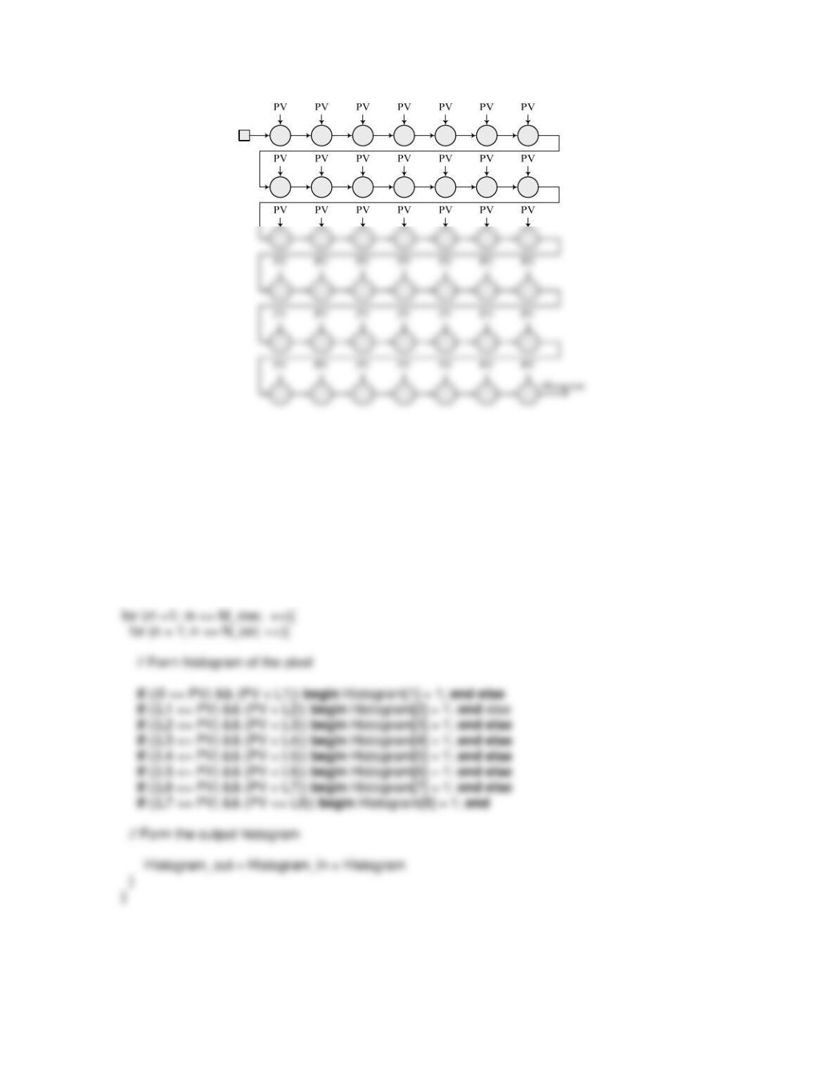
(1) Baseline Machine An alternative implementation forms a baseline processor using
only combinational logic. It associates an identical functional unit (FU) with each pixel.
The DFG of the FU is shown below:
pixel value
A NLP for the baseline processor is listed below. The array was not augmented by
additional processors at the boundary. Instead, the first processor has an input of 0
representing the histogram of its left-adjacent neighbor.
// Initialize the histogram of the first pixel
for (k = 1; k <= N_bins; k = k + 1) {Histogram[k] = 0;}
// Process the array
The input to the Verilog model of the baseline processor is a vector of the bits of the pixel
values in the array; the output of the processor is a vector of bits of the levels of the
histogram of the image.
module Image_Histogram_Processor_Baseline # (
parameter pixel_size = 8, H_bin_size = 6, N_bins = 8, N_col = 8, M_row = 6, N_Level = 8)(
output [0: H_bin_size*N_bins -1] Histogram_bits,
input [1: pixel_size * N_col * M_row] pixel_bits
/*
always @ (pixel_bits) begin
PV[1] = pixel_bits [ 1: pixel_size];
PV[2] = pixel_bits [pixel_size + 1: 2*pixel_size];
PV[3] = pixel_bits [ 2*pixel_size + 1: 3*pixel_size];
PV[4] = pixel_bits [ 3*pixel_size + 1: 4*pixel_size];
PV[5] = pixel_bits [ 4*pixel_size + 1: 5*pixel_size];
PV[6] = pixel_bits [ 5*pixel_size + 1: 6*pixel_size];
PV[18] = pixel_bits [17*pixel_size + 1: 18*pixel_size];
PV[19] = pixel_bits [18*pixel_size + 1: 19*pixel_size];
PV[20] = pixel_bits [19*pixel_size + 1: 20*pixel_size];
PV[21] = pixel_bits [20*pixel_size + 1: 21*pixel_size];
PV[22] = pixel_bits [21*pixel_size + 1: 22*pixel_size];
PV[23] = pixel_bits [22*pixel_size + 1: 23*pixel_size];
PV[24] = pixel_bits [23*pixel_size + 1: 24*pixel_size];
PV[25] = pixel_bits [24*pixel_size + 1: 25*pixel_size];