PROBLEM 9.48
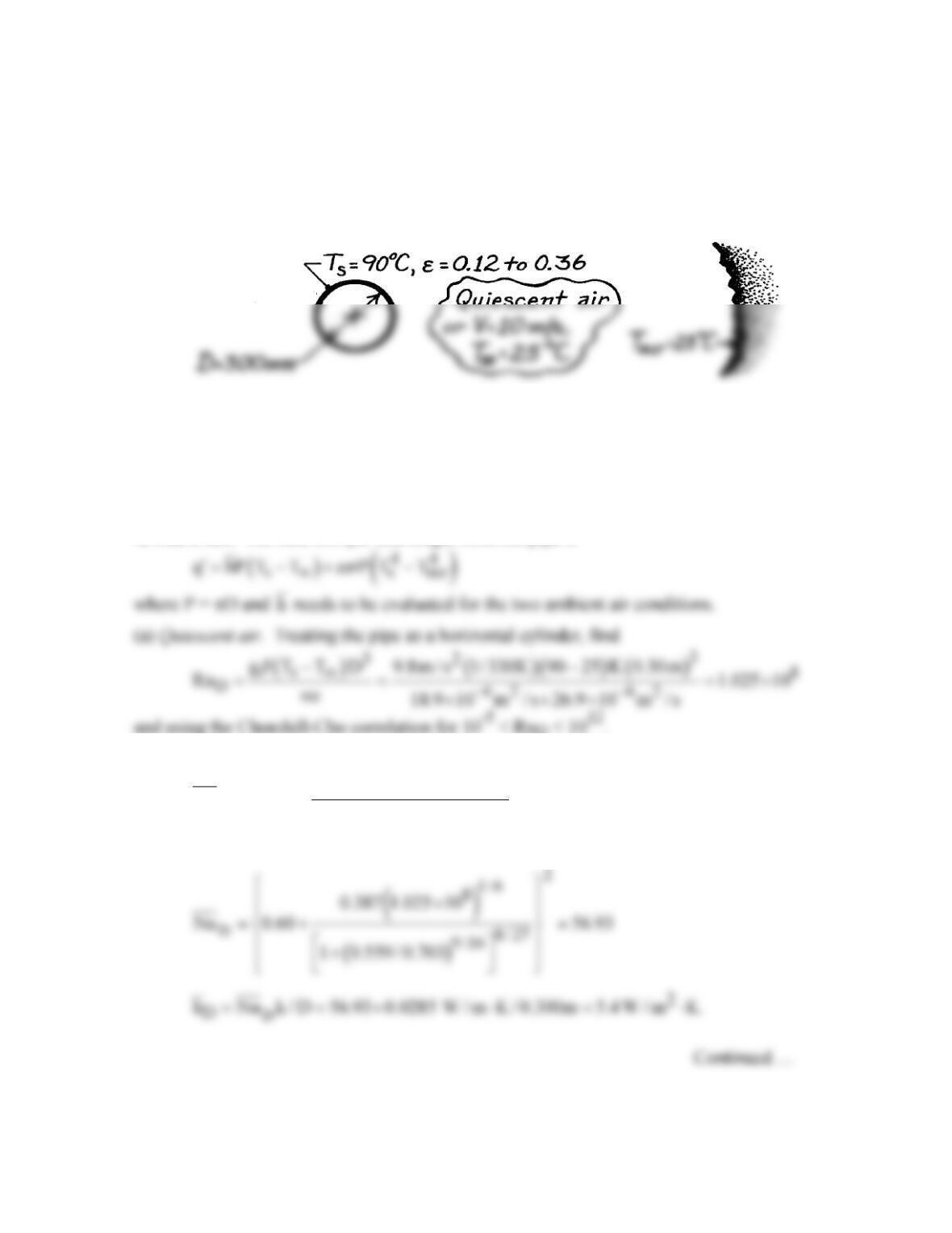
KNOWN: Insulated, horizontal pipe with aluminum foil having emissivity which varies from
0.12 to 0.36 during service. Pipe diameter is 300 mm and its surface temperature is 90°C.
FIND: Effect of emissivity degradation on heat loss with ambient air at 25°C and (a)
quiescent conditions and (b) cross-wind velocity of 10 m/s.
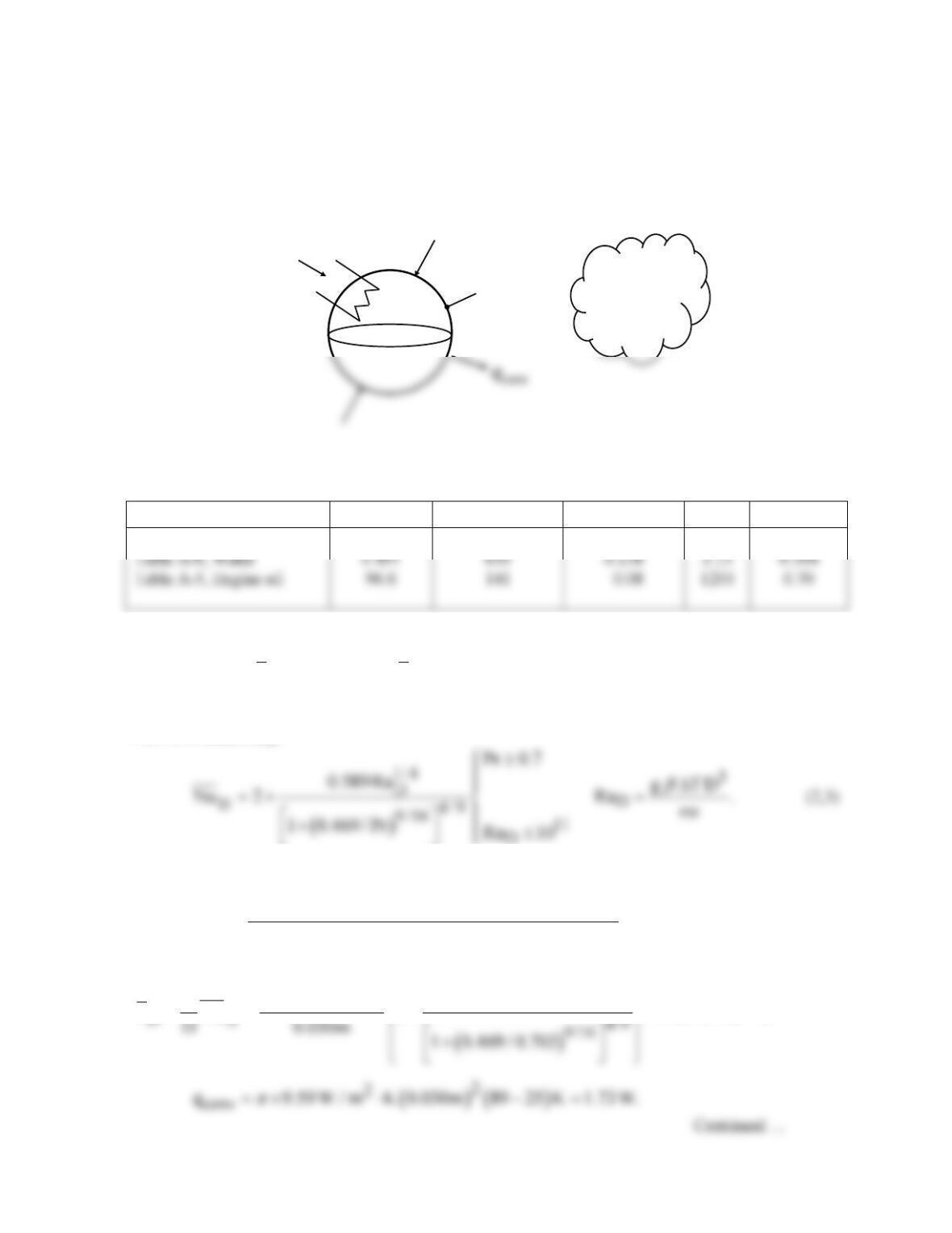
SCHEMATIC:
ASSUMPTIONS: (1) Steady-state conditions, (2) Surroundings are large compared to pipe,
(3) Pipe has uniform temperature.
PROPERTIES: Table A-4, Air (Tf = (90 + 25)°C/2 = 330K, 1 atm): ν = 18.9 × 10⁻⁶ m2/s, k
= 28.5 × 10⁻³ W/m⋅K, a = 26.9 × 10⁻⁶ m2/s, Pr = 0.703.
ANALYSIS: The heat loss per unit length from the pipe is
( )
D
2
1/6
D
8/ 27
9 /16
0.387Ra
Nu 0.60
1 0.559 / Pr
= +
+
PROBLEM 9.48 (Cont.)
Hence, the heat loss is
The radiation effect accounts for 16 and 35%, respectively, of the heat rate.
and using the Hilpert correlation where C = 0.027 and m = 0.805 from Table 7.2,
Recognizing that combined free and forced convection conditions may exist, from Eq. 9.64
with n = 4,
we find forced convection dominates. Hence, the heat loss is
The radiation effect accounts for 5 and 13%, respectively, of the heat rate.
COMMENTS: (1) For high velocity wind conditions, radiation losses are quite low and the
degradation of the foil is not important. However, for low velocity and quiescent air
conditions, radiation effects are significant and the degradation of the foil can account for a
nearly 25% change in heat loss.
PROBLEM 9.49
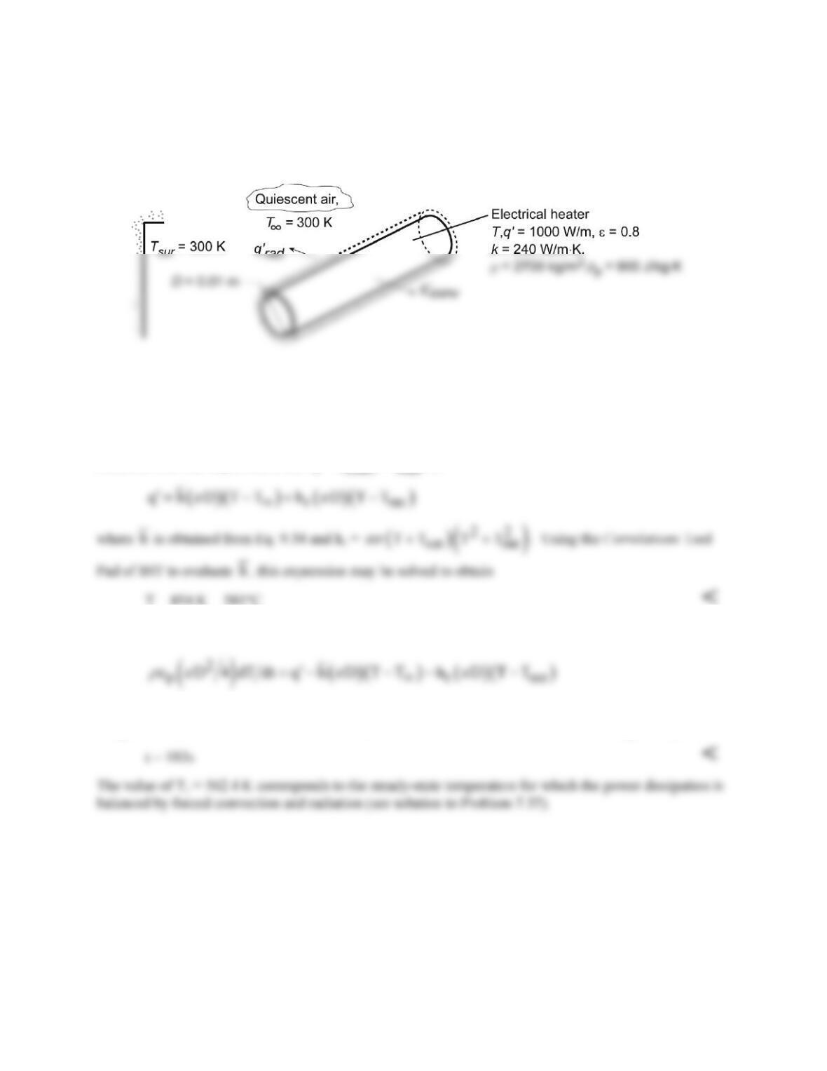
KNOWN: Diameter, emissivity, and power dissipation of cylindrical heater. Temperature of ambient
air and surroundings.
FIND: Steady–state temperature of heater and time required to come within 10°C of this temperature.
SCHEMATIC:
ASSUMPTIONS: (1) Air is quiescent, (2) Duct wall forms large surroundings about heater, (3) Heater
may be approximated as a lumped capacitance.
PROPERTIES: Table A.4, air (Obtained from Properties Tool Pad of IHT).
ANALYSIS: Performing an energy balance on the heater, the final (steady–state) temperature may be
obtained from the requirement that
conv rad
qq q
′′ ′
= +
, or
T = 854 K = 581°C <
Under transient conditions, the energy balance is of the form,
st conv rad
E qq q
′ ′′ ′
=−−
, or
Using the IHT Lumped Capacitance model with the Correlations Tool Pad, the above expression is
integrated from t = 0, for which Ti = 562.4 K, to the time for which T = 844 K. The integration yields
COMMENTS: The forced convection coefficient (Problems 7.36 and 7.37) of 105 W/m2⋅K is much
larger than that associated with free convection for the steady–state conditions of this problem (14.6
W/m2⋅K). However, because of the correspondingly larger heater temperature, the radiation coefficient
with free convection (42.9 W/m2⋅K) is much larger than that associated with forced convection (15.9
W/m2⋅K).
PROBLEM 9.50
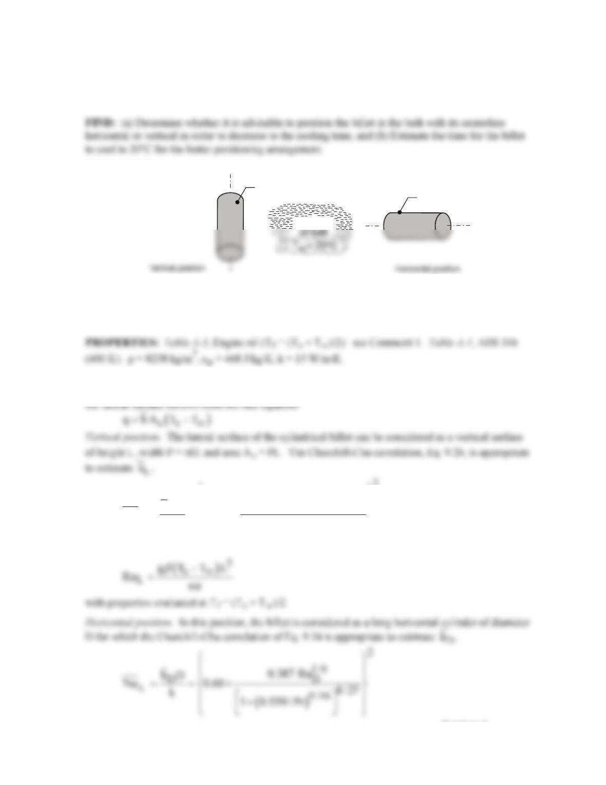
KNOWN: A billet of stainless steel AISI 316 with a diameter of 150 mm and length 500 mm
emerges from a heat treatment process at 200°C and is placed into an unstirred oil bath maintained at
20°C.
SCHEMATIC:
Unstirred
Billet
,
D = 150 mm
L = 500 mm
T = 200 C
s o
T = 200 C
s o
ASSUMPTIONS: (1) Steady-state conditions for part (a), (2) Oil bath approximates a quiescent
fluid, (3) Consider only convection from the lateral surface of the cylindrical billet; and (4) For part
(b), the billet has a uniform initial temperature.
ANALYSIS: (a) For the purpose of determining whether the horizontal or vertical position is
preferred for faster cooling, consider only free convection from the lateral surface. The heat loss from
( )
L
2
1/6
LL
8/ 27
9 /16
0.387 Ra
hL
Nu 0.825
k1 0.492 / Pr
= = +
+
Continued …
PROBLEM 9.50 (Cont.)
with properties evaluated at Tf. The heat transfer area is also As = PL.
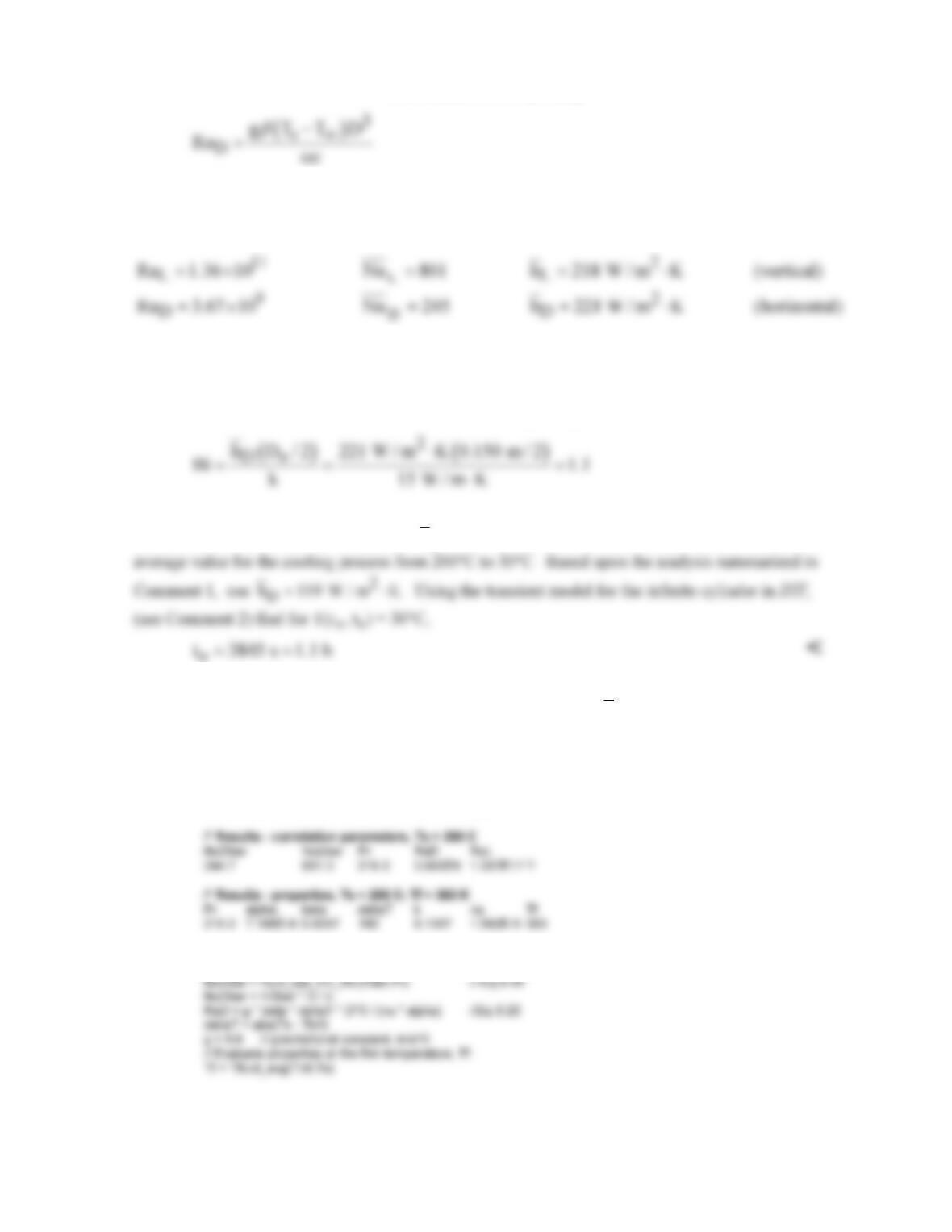
Using the foregoing relations in IHT with the thermophysical properties library as shown in Comment
1, the analysis results are tabulated below.
Recognize that the orientation has a small effect on the convection coefficient for these conditions,
but we’ll select the horizontal orientation as the preferred one.
(b) Evaluate first the Biot number to determine if the lumped capacitance method is valid.
Since Bi >> 0.1, the spatial effects are important and we should use the one-term series approximation
for the infinite cylinder, Eq. 5.52. Since
D
h will decrease as the billet cools, we need to estimate an
COMMENTS: (1) The IHT code using the convection correlation functions to estimate the
coefficients is shown below. This same code was used to calculate
D
h
for the range 30 ≤ Ts ≤ 200°C
and determine that an average value for the cooling period of part (b) is 119 W/m2⋅K.
/* Results – convection coefficients, Ts = 200 C
hDbar hLbar D L Tinf_C Ts_C
221.4 217.5 0.15 0.5 20 200 */
/* Correlation description: Free convection (FC), long horizontal cylinder (HC),
10^–5<=RaD<=10^12, Churchill–Chu correlation, Eqs 9.25 and 9.34 . See Table 9.3 . */
Continued …..

PROBLEM 9.50 (Cont.)
/* Correlation description: Free convection (FC) for a vertical plate (VP), Eqs 9.25 and 9.26 .
// Input variables
// Engine Oil property functions : From Table A.5
// Units: T(K)
// Conversions
Tinf_C = Tinf – 273
Ts_C = Ts – 273
(2) The portion of the IHT code used for the transient analysis is shown below. Recognize that we
/* Results – time to cool to 30 C, center and surface temperatures
D T_xt_C Ti_C Tinf_C r h t
0.15 30.01 200 20 0.075 119 3845 */
0.15 33.19 200 20 0 119 3845
// Transient conduction model, cylinder (series solution)
PROBLEM 9.51
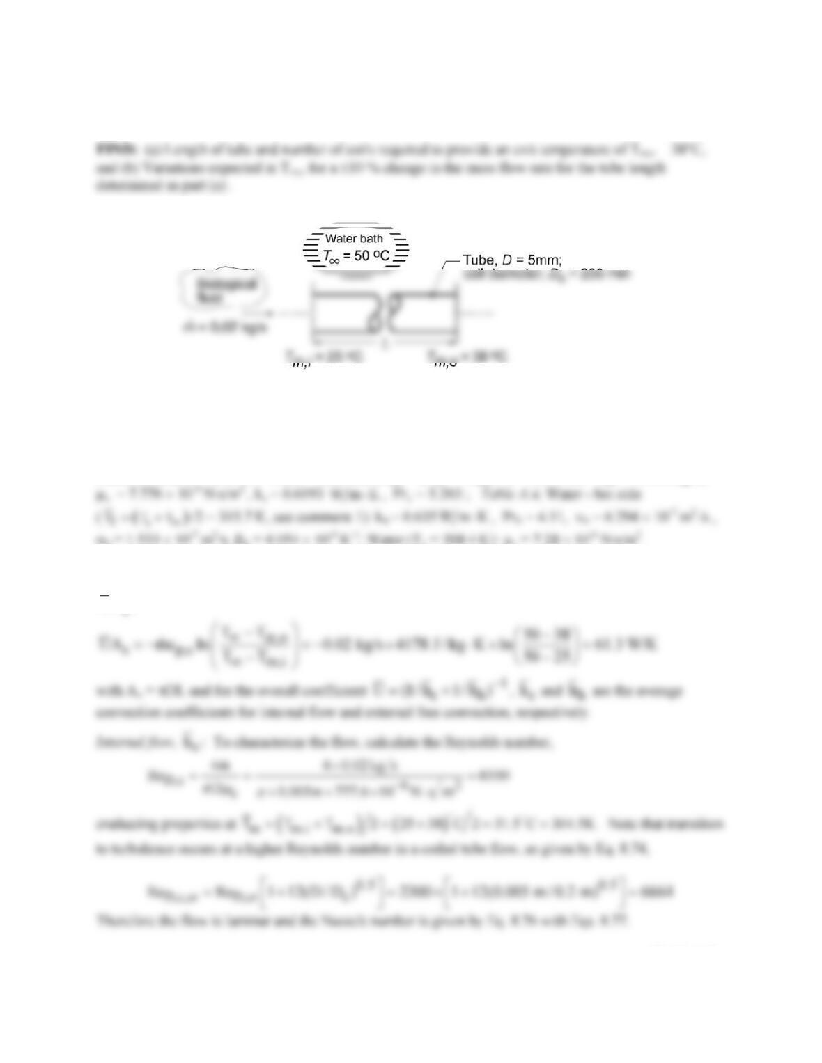
KNOWN: Biological fluid with prescribed flow rate and inlet temperature flowing through a coiled,
thin–walled, 5-mm diameter tube submerged in a large water bath maintained at 50°C.
SCHEMATIC:
ASSUMPTIONS: (1) Steady-state conditions, (2) Coiled tube approximates a horizontal tube
experiencing free convection in a quiescent, extensive medium (water bath), (3) Biological fluid has
thermophysical properties of water, (4) Negligible tube wall thermal resistance, (5) Biological fluid flow
is incompressible with negligible viscous dissipation, and (6) Flow in tube is fully developed.
PROPERTIES: Table A.4 Water – cold side (Tm,c = (Tm,i + Tm,o ) / 2 = 304.5 K) : cp,c = 4178 J/kg⋅K,
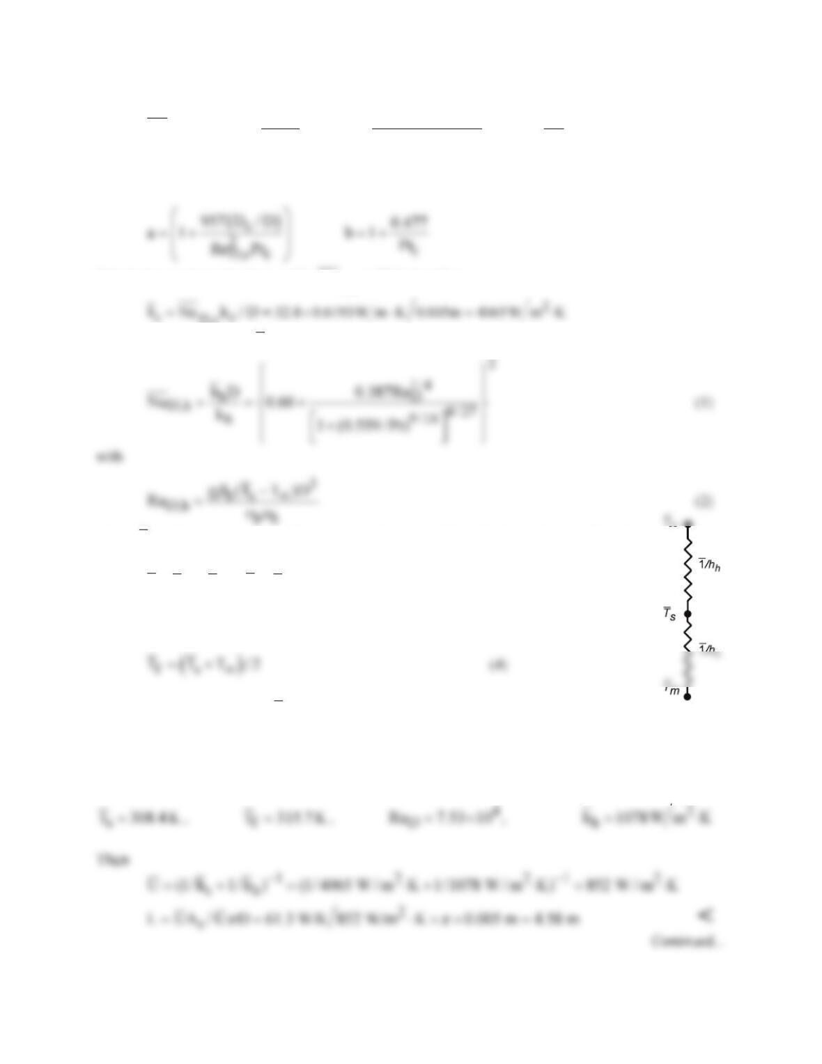
ANALYSIS: (a) Following the treatment of Section 8.3.3, the coil experiences internal flow of the cold
biological fluid (c) and free convection with the external hot fluid (h). From Eq. 8.45a, we can solve for
UA
,
Continued…
PROBLEM 9.51 (Cont.)
D,c
1/3
1.5 0.14
0.5
3D,c c c
s
Re (D/D )
4.343
Nu 3.66+ +1.158
ab
µ
µ
=
where
Substituting numerical values yields D,c
Nu = 32.8, therefore
External free convection ,
h
h
: For the horizontal tube, Eq. 9.34,
where
s
T
is the average tube wall temperature determined from the thermal circuit for which
( ) ( )
cm s hs
hT T hT T
∞
−= −
(3)
and the average film temperature at which to evaluate properties is
We need to guess a value for
s
T
and iterate the solution of the system of equations (1-4) and property
evaluation until all the equations are satisfied. See Comments 1 and 2.
Results of the analysis: Using the foregoing relations in IHT (see Comment 2) the following results were
obtained
PROBLEM 9.51 (Cont.)
From knowledge of the tube length with the diameter of the coil Dc = 200 mm, the number of coils
required is
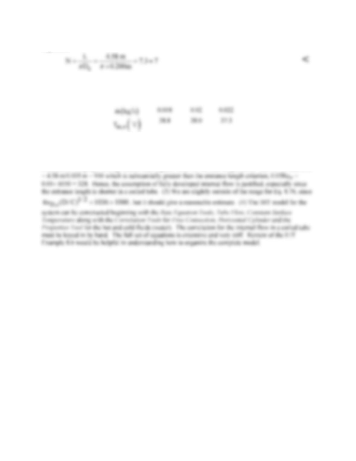
(b) With the length fixed at L = 4.58 m, we can backsolve the foregoing IHT workspace model to find
what effect a ±10% change in the mass flow rate has on the outlet temperature, Tm,o . The results of the
analysis are tabulated below.
That is, a ±10 % change in the flow rate causes less than a ±1°C change in the outlet temperature. While
this change seems quite small, the effect on biological processes can be significant.
COMMENTS: (1) For the hot fluid, the Properties section shows the relevant thermophysical properties
evaluated at the proper average (rather than a guess value for the film temperature). (2) For the tube L/D
PROBLEM 9.52
KNOWN: Volume, thermophysical properties, and initial and final temperatures of a
pharmaceutical. Diameter and length of submerged tubing. Pressure of saturated steam flowing
through the tubing.
FIND: (a) Initial rate of heat transfer to the pharmaceutical, (b) Time required to heat the
pharmaceutical to 70°C and the amount of steam condensed during the process.
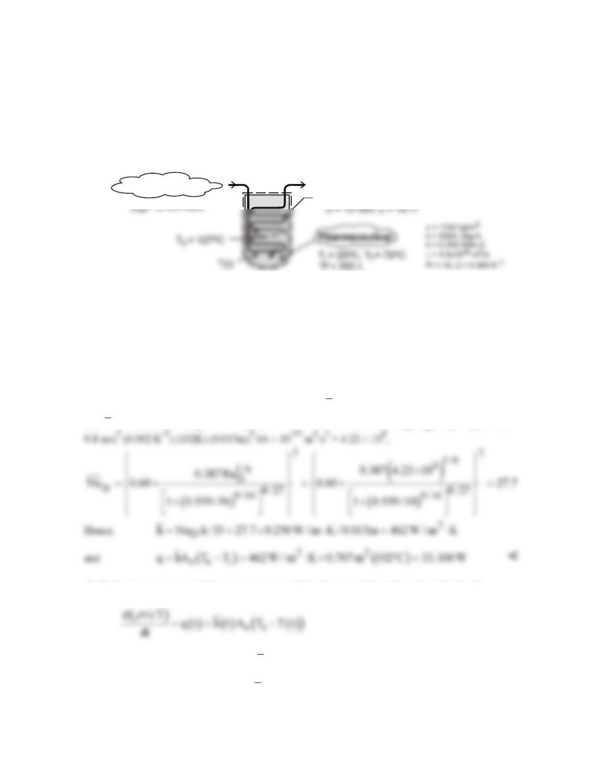
SCHEMATIC:
Tubing
Saturated steam
ASSUMPTIONS: (1) Pharmaceutical may be approximated as an infinite, quiescent fluid of
uniform, but time-varying temperature, (2) Free convection heat transfer from the coil may be
approximated as that from a heated, horizontal cylinder, (3) Negligible thermal resistance of
condensing steam and tube wall, (4) Negligible heat transfer from tank to surroundings, (5) Constant
properties.
PROPERTIES: Table A-4, Saturated water (2.455 bars): Tsat = 400K = 127°C, hfg = 2.183 × 10⁶
J/kg. Pharmaceutical: See schematic.
ANALYSIS: (a) The initial rate of heat transfer is
( )
ss i
q hA T T ,= −
where As = πDL = 0.707 m2
and
h
is obtained from Eq. 9.34. With
a
=
ν
/Pr = 4.0 × 10⁻⁷ m2/s and RaD = g
β
(Ts – Ti) D3/
aν
=
(b) Performing an energy balance at an instant of time for a control surface about the liquid,
where the Rayleigh number, and hence
h,
changes with time due to the change in the temperature of
the liquid. Integrating the foregoing equation using the DER function of IHT, the following results
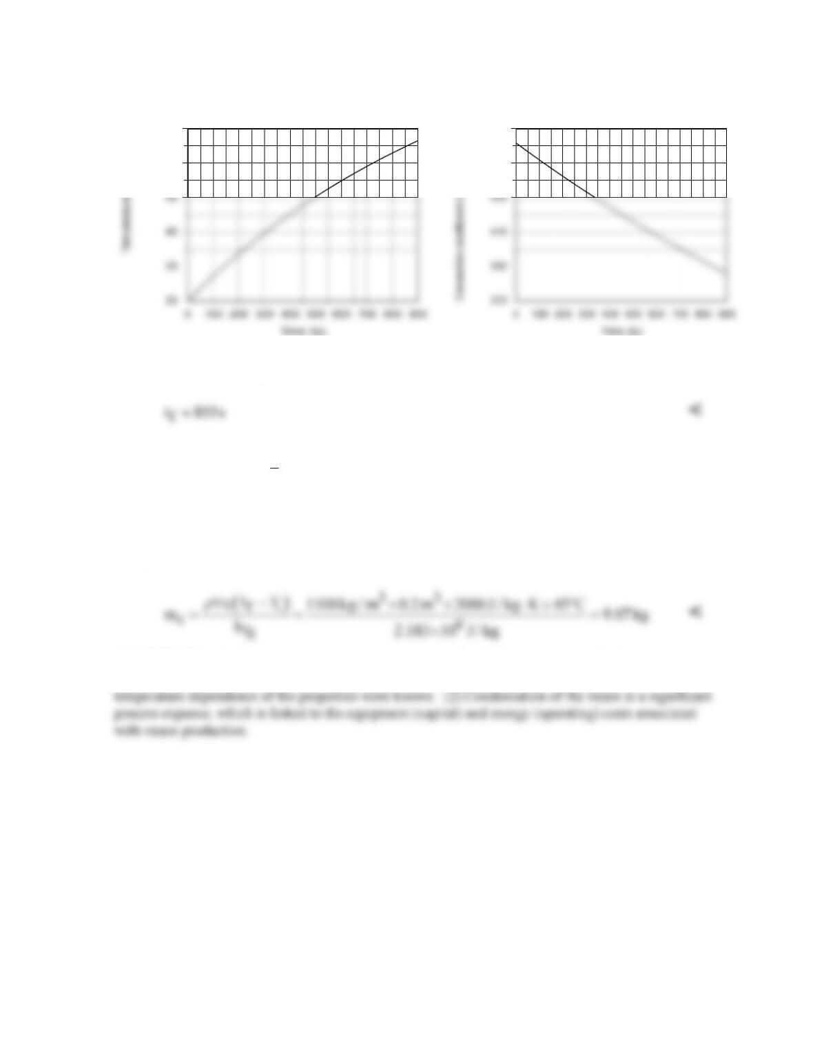
are obtained for the variation of T and
h
with t.
Continued …
PROBLEM 9.52 (Cont.)
The time at which the liquid reaches 70°C is
The temperature increases at a decreasing rate due to the corresponding reduction in (Ts – T), and
hence reductions in
D
Ra , h and q.
The Rayleigh number decreases from 4.22 × 10⁶ to 2.16 × 10⁶,
while the heat rate decreases from 33,300 to 14,000 W. The convection coefficient decreases
approximately as (Ts – T)1/3, while q ~ (Ts – T)4/3. The latent energy released by the condensed
steam corresponds to the increase in thermal energy of the pharmaceutical. Hence,
c fg
mh =
( )
fi
cT T ,
ρ
∀−
and
COMMENTS: (1) Over such a large temperature range, the fluid properties are likely to vary
significantly, particularly
ν
and Pr. A more accurate solution could therefore be performed if the
65
75
450
470
PROBLEM 9.53
KNOWN: Fin of uniform cross section subjected to prescribed conditions.
FIND: Tip temperature and fin effectiveness based upon (a) average values for free convection and
radiation coefficients and (b) local values using a numerical method of solution.
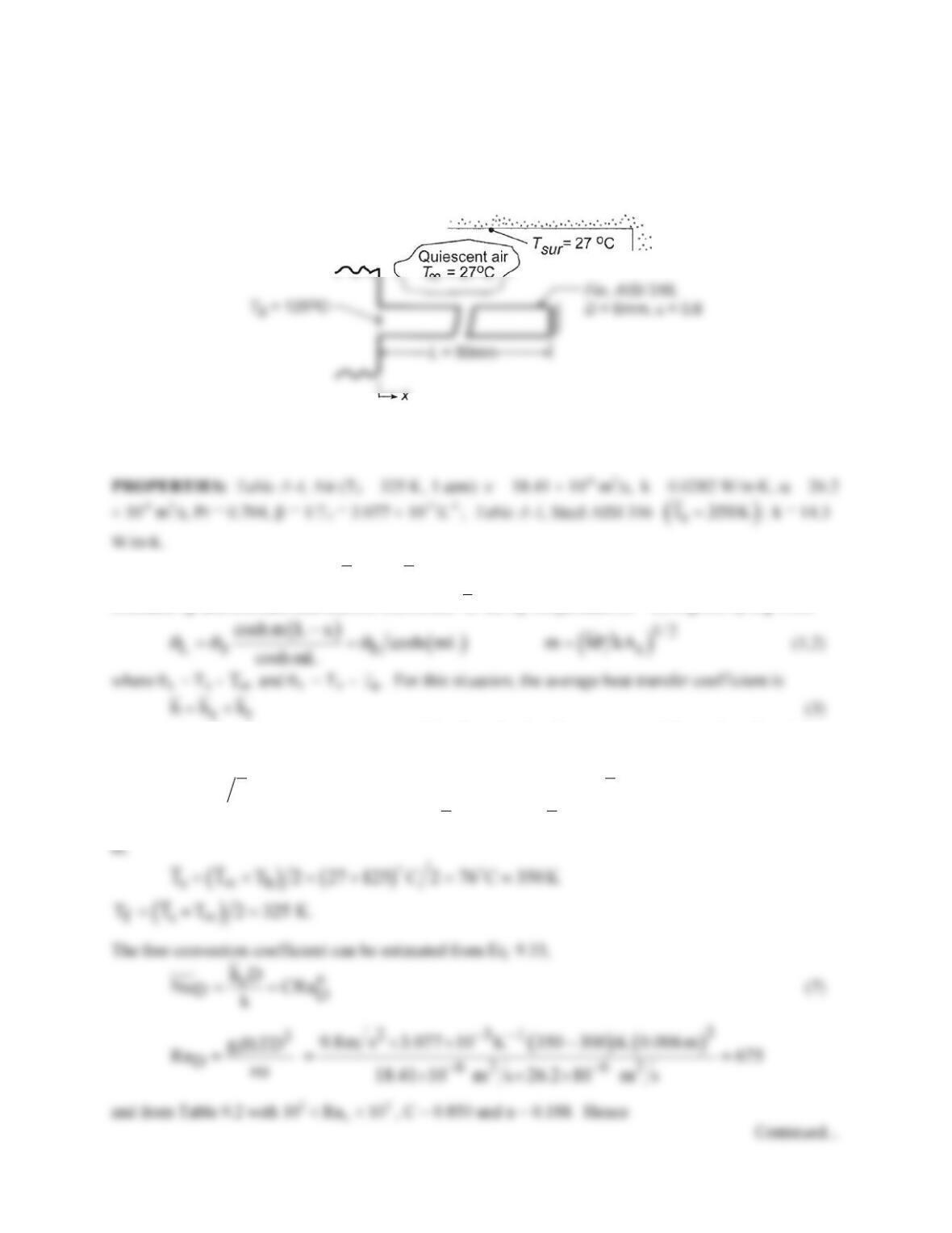
SCHEMATIC:
ASSUMPTIONS: (1) Steady-state conditions, (2) Surroundings are isothermal and large compared to
the fin, (3) One-dimensional conduction in fin, (4) Constant fin properties, (5) Tip of fin is insulated, (6)
Fin surface is diffuse–gray.
ANALYSIS: (a) Average value
c
h
and
r
h:
From Table 3.4 for a fin of constant cross section with an
insulated tip and constant heat transfer coefficient
h,
the tip temperature (x = L) is given by Eq. 3.80,
T∞
and is evaluated at the average temperature of the fin. The fin effectiveness εf follows from Eqs. 3.81
and 3.86
( )
( )
1/ 2
f f c,b b f c b
q hA , q M tanh mL , M hPkA .
εθ θ
≡ =⋅=
(4,5,6)
To estimate the coefficients, assume a value of
s
T
; the lowest
s
T
occurs when the tip reaches
T∞
. That
PROBLEM 9.53 (Cont.)
( )
0.188 2
c
0.0282 W m K
h 0.850 675 13.6 W m K.
0.006m
⋅
=×=⋅
(8) <
The radiation coefficient is estimated from Eq. 1.9,
Evaluate the fin parameters, Eq. (2) and (6) with
( )
2
2 2 52
c
P D 0.006m 1.885 10 m A D 4 0.006m 4 2.827 10 m
ππ π π
−−
==×=× == =×
From Eq. (1), the tip temperature is
( )
()
1
L Lb
T T 125 27 K cosh 29.21m 0.050m 43.2K
θ
−
=−= − × =
L
T 70.2 C 343 K= =
. <
f1.039 W 18.3 / W m K 2.827 10 m 125 27 K 20.5
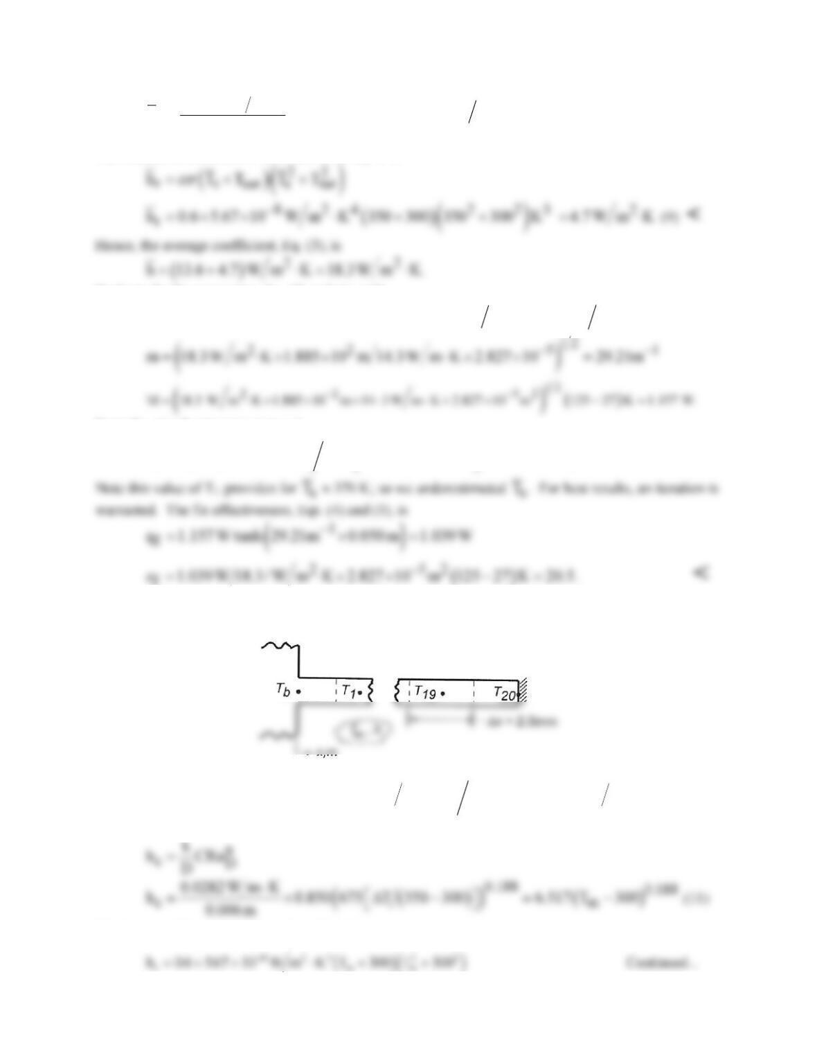
(b) Local values hc and hr: Consider the nodal arrangement for using a numerical method to find the tip
temperature TL, the heat rate qf, and the fin effectiveness ε.
From an energy balance on a control volume about node m, the finite–difference equation is of the form
( )
()
( )
()
22
m m1 m1 c r r c
T T T h h 4 x kD T 2 h h 4 x kD
+− ∞
= + ++ D ++ D
. (10)
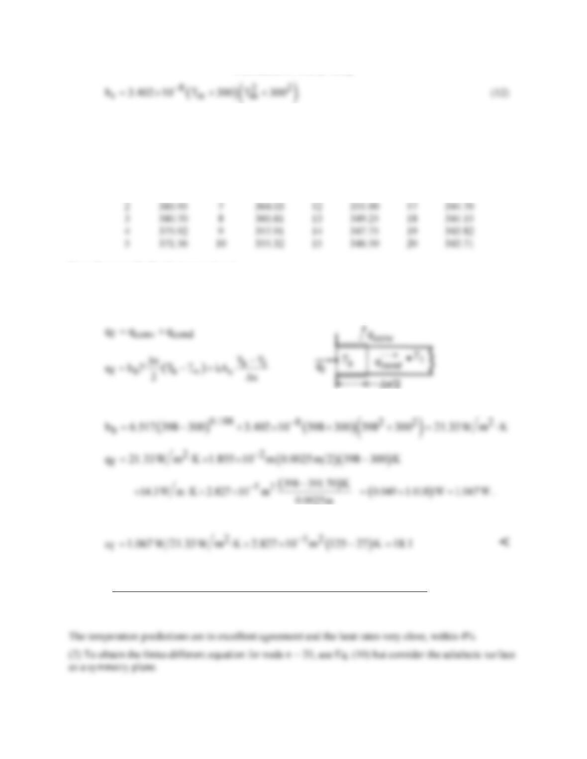
The local coefficient hc follows from Eq. (3), with Eq. 9.33, yielding
The local coefficient hr follows from Eq. (9),
PROBLEM 9.53 (Cont.)
The 20-node system of finite-difference equations based upon Eq. (10) with the variable coefficients hc
and hr prescribed Eqs. (11) and (12), respectively, can be solved simultaneously using IHT or another
approach. The temperature distribution is
Node
Tm(K)
Node
Tm(K)
Node
Tm(K)
Node
Tm(K)
1
391.70
6
367.61
11
353.02
16
345.49
2
385.95
7
364.03
12
351.00
17
344.70
3
380.70
8
360.81
13
349.25
18
344.15
4
375.92
9
357.91
14
347.75
19
343.82
5
371.56
355.32
15
346.50
20
343.71
From these results the tip temperature is
L fd
T T 343.7 K 70.7 C= = =
. <
The fin heat rate follows from an energy balance for the control surface about node b.
where hb follows from Eqs. (11) and (12), with Tb = 125°C = 398 K,
The effectiveness follows from Eq. (4)
COMMENTS: (1) The results by the two methods of solution compare as follows:
Coefficients
T(L),K
qf(W)
εf
average
343.1
1.039
20.5
local
343.7
1.067
18.1
PROBLEM 9.54
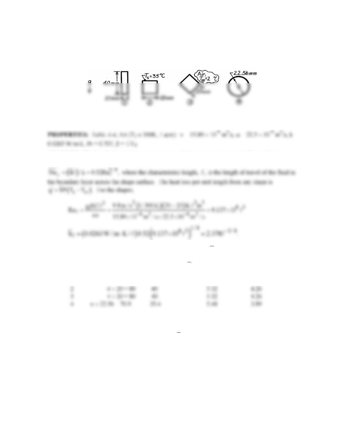
KNOWN: Horizontal tubes of different shapes each of the same cross–sectional area transporting a
hot fluid in quiescent air. Lienhard correlation for immersed bodies.
FIND: Tube shape which has the minimum heat loss to the ambient air by free convection.
SCHEMATIC:
ASSUMPTIONS: (1) Ambient air is quiescent, (2) Negligible heat loss by radiation, (3) All shapes
have the same cross–sectional area and uniform surface temperature.
ANALYSIS: The Lienhard correlation approximates the laminar convection coefficient for an
immersed body on which the boundary layer does not separate from the surface by
For the shapes,
is half the total wetted perimeter P. Evaluating
h and q ,
′
find
Shape P (mm)
( )
mm
()
2
h W/m K⋅
( )
q W/m
′
1 2 × 40 + 2 × 10 = 100 50 5.03 5.03
Hence, it follows that shape 4 has the minimum heat loss. <
COMMENTS: For a cylinder, using Eq. 9.34, find
2
h 5.15 W / m K.= ⋅
The Lienhard
approximation for the cylinder is 6% high relative to the Churchill and Chu correlation.
55
PROBLEM 9.55
KNOWN: Sphere of 2-mm diameter immersed in a fluid at 300 K.
FIND: (a) The conduction limit of heat transfer from the sphere to the quiescent, extensive fluid,
NuD,cond = 2; (b) Considering free convection, surface temperature at which the Nusselt number is twice
that of the conduction limit for the fluids air and water; and (c) Considering forced convection, fluid
velocity at which the Nusselt number is twice that of the conduction limit for the fluids air and water.
SCHEMATIC:
ASSUMPTIONS: (1) Sphere is isothermal, (2) For part (a), fluid is stationary, and (3) For part (b), fluid
is quiescient, extensive.
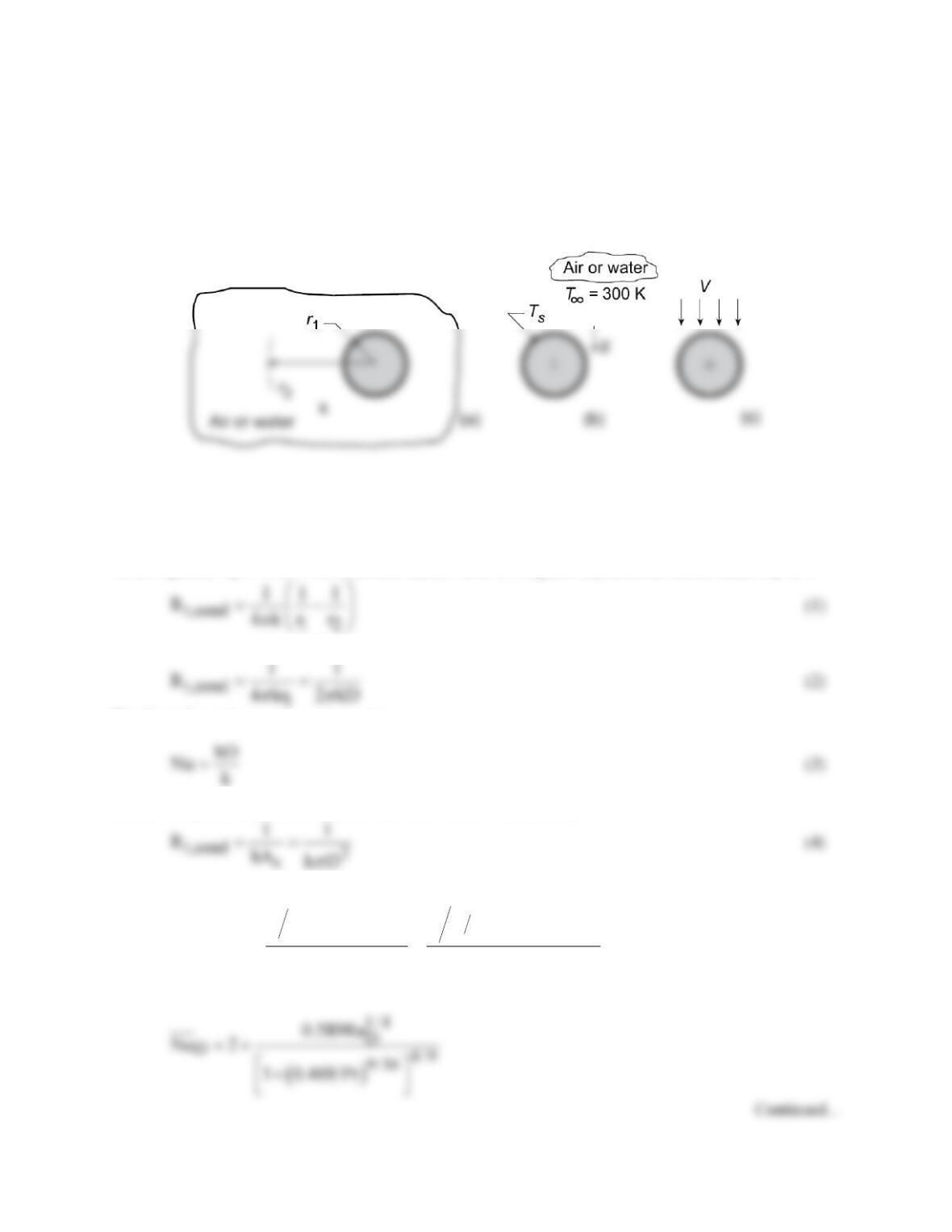
ANALYSIS: (a) Following the hint provided in the problem statement, the thermal resistance of a
hollow sphere, Eq. 3.40 of inner and outer radii, r1 and r2 , respectively, and thermal conductivity k, is
and as r2 → ∞, that is the medium is extensive
The Nusselt number can be expressed as
and the conduction resistance in terms of a convection coefficient is
Combining Eqs. (3) and (4)
()
( )
()
2
2
t,cond
D,cond
1 1 2 kD D D
1R D D
Nu 2
kk
ππ
π
= = =
<
(b) For free convection, the recommended correlation, Eq. 9.35, is
PROBLEM 9.55 (Cont.)
3
Ds
g TD
Ra T T T
β
νa
∞
D
= D= −
where properties are evaluated at Tf = (Ts + T∞) / 2. What value of Ts is required for
D
Nu 4=
for the
fluids air and water? Using the IHT Correlations Tool, Free Convection, Sphere and the Properties
Tool for Air and Water, find
(c) For forced convection, the recommended correlation, Eq. 7.56, is
where properties are evaluated at
T
∞
, except for µs evaluated at Ts .What value of V is required for
D
Nu 4=
if the fluids are air and water? Using the IHT Correlations Tool, Forced Convection, Sphere
and the Properties Tool for Air and Water, find (evaluating all properties at 300 K)
COMMENTS: (1) For water,
D D,cond
Nu 2 Nu= ×
can be achieved by DT ≈ 1 for free convection
and with very low velocity, V< 0.002 m/s, for forced convection.
PROBLEM 9.56
KNOWN: Diameter of sphere with embedded electrical heater. Surface temperature. Freestream
temperature of surrounding medium.
FIND: Required electrical power for these media: (a) atmospheric air, (b) water, (c) engine oil.
SCHEMATIC:
D= 30 mm
T
s
= 89°C
+
Quiescent
medium,
T
∞
= 25°C
P
e
ASSUMPTIONS: (1) Negligible surface radiation effects, (2) Extensive and quiescent media.
PROPERTIES: Evaluated at Tf = (Ts + T∞)/2 = 330K:
ν⋅
106, m2/s
k
⋅
103, W/m
⋅
K
a⋅
106, m2/s
Pr
β⋅
103, K-1
Table A-4, Air (1 atm)
18.91
28.5
26.9
0.703
3.03
ANALYSIS: The electrical power (Pe) required to offset convection heat transfer is
( ) ( )
2
conv s s s
q hA T T hD T T .
π
∞∞
= −= −
(1)
The free convection heat transfer coefficient for the sphere can be estimated from Eq. 9.35 using Eq.
9.25 to evaluate RaD.
(a) For air
()
( ) ( )
3
2 31
5
D62 62
9.8m / s 3.03 10 K 89 25 K 0.030m
Ra 1.01 10
18.91 10 m / s 26.9 10 m / s
−−
−−
×−
= = ×
× ××
()
1/ 4
5
2
0.589 1.01 10
k 0.0285 W / m K
h Nu 2 9.59 W / m K
×
⋅
==+=⋅
PROBLEM 9.56 (Cont.)
(b,c) Summary of the calculations above and for water and engine oil:
Fluid RaD
()
2
D
h W/m K⋅
q(W)
Air 1.01 × 10⁵ 9.59 1.73 <
PROBLEM 9.57
KNOWN: Temperatures and spacing of vertical, isothermal plates.
FIND: (a) Shape of velocity distribution, (b) Forms of mass, momentum and energy equations for
laminar flow, (c) Expression for the temperature distribution, (d) Vertical pressure gradient, (e)
Expression for the velocity distribution.
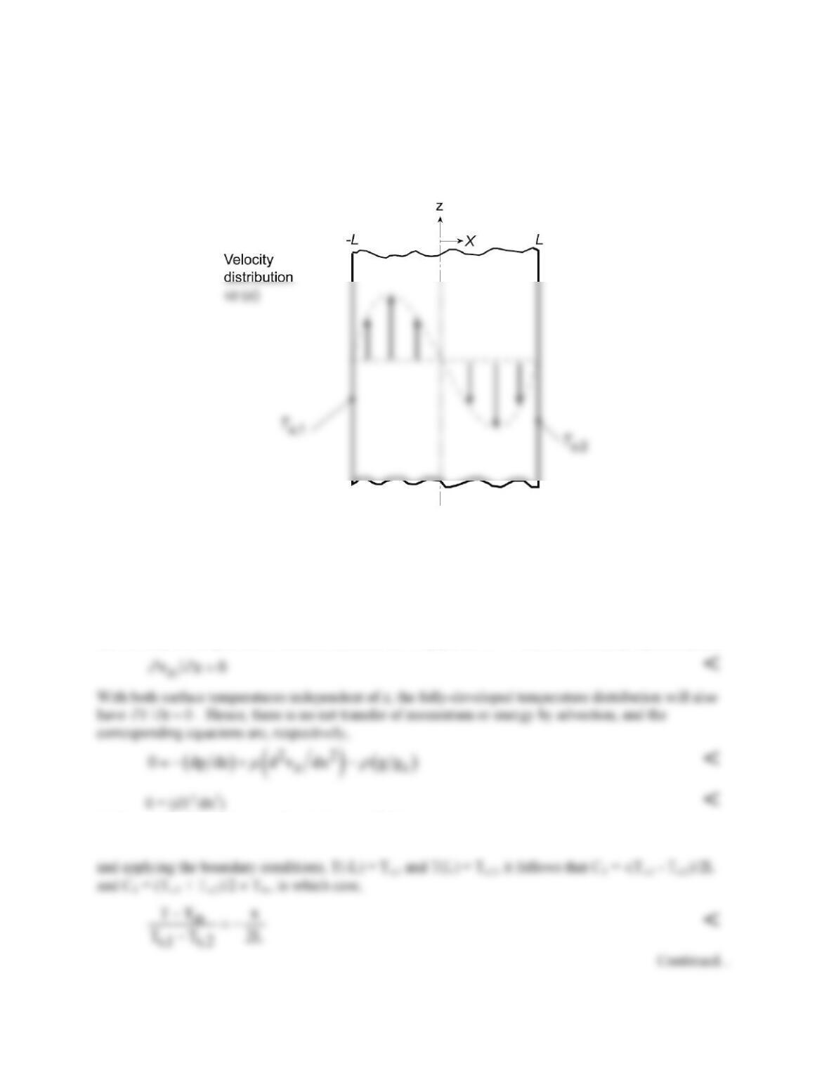
SCHEMATIC:
ASSUMPTIONS: (1) Laminar, incompressible, fully-developed flow, (2) Constant properties, (3)
Negligible viscous dissipation, (4) Boussinesq approximation.
ANALYSIS: (a) For the prescribed conditions, there must be buoyancy driven ascending and
descending flows along the surfaces corresponding to Ts,1 and Ts,2, respectively (see schematic).
However, conservation of mass dictates equivalent rates of upflow and downflow and, assuming constant
properties, inverse symmetry of the velocity distribution about the midplane.
(b) For fully–developed flow, which is achieved for long plates, vx = 0 and the continuity equation yields
(c) Integrating the energy equation twice, we obtain
T = C1x + C2