21
Problem 9.13
An umbrella structure has been idealized as an assemblage
of three flexural elements with lumped masses at the nodes
and determine the mass matrix.
(c) Formulate the equations of motion governing the DOFs
in part (b) when the excitation is (i) horizontal ground
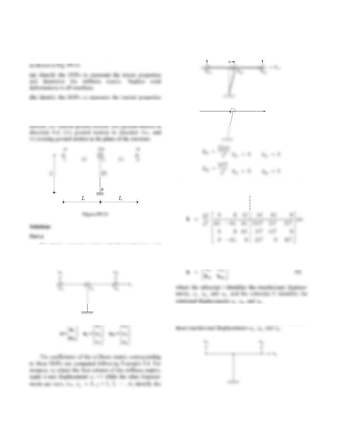
The elastic properties of the umbrella (neglecting axial
deformation of the elements) are represented by six DOFs:
three translational displacements and three rotations.
resulting elastic forces, and by statics obtain the stiffness
coefficients:
u = 1
1k21
k31
12 EI /L3
6EI /L2
Other columns of k are determined similarly. The complete
stiffness matrix is
12 0 0 6 0 0
01206 06
L
LL
The stiffness matrix can be written in partitioned form as
follows:
Part b
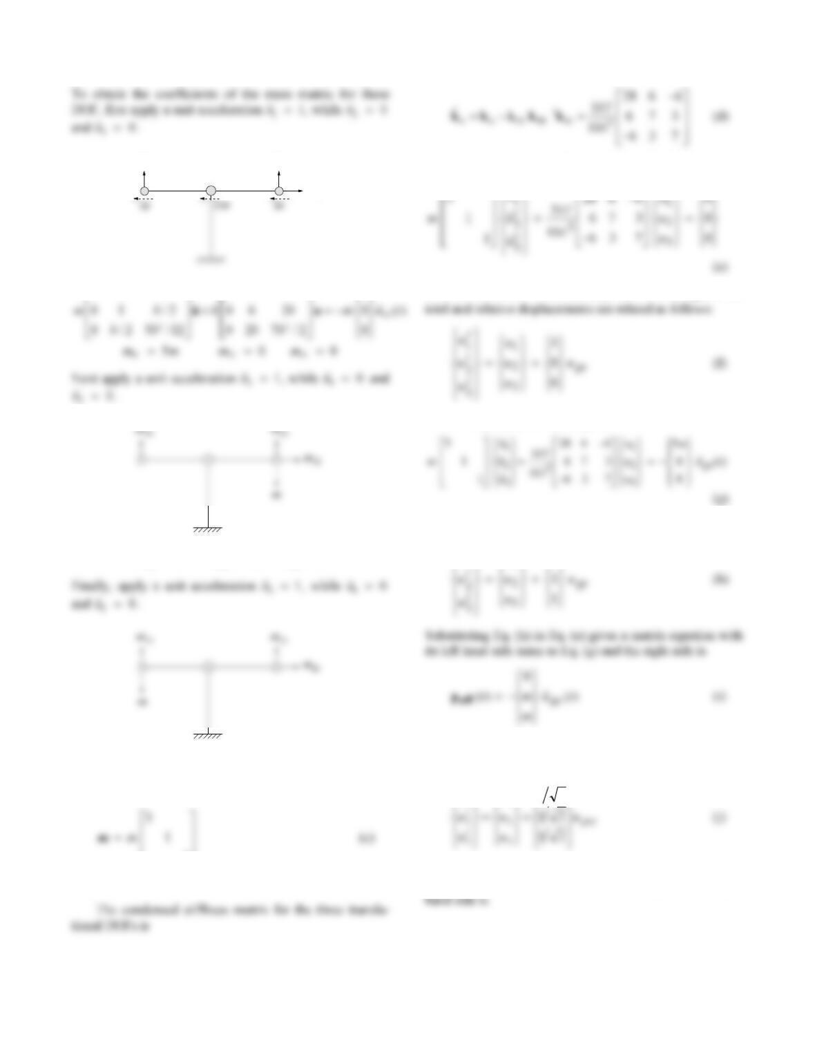
The DOFs representing the inertial properties are the
22
m31 m21
m11
10 0 60 0 1
12 0m 22
mm 32 0m
13 0m 23 0m 33
mm
Thus, the mass matrix is
1
Part c
The equations governing the translational DOFs are
u
t
(i) If the excitation is horizontal ground motion u
t
gx ()
, the
Substituting Eq. (f) in Eq. (e) gives
(ii) If the excitation is vertical ground motion u
t
gy ()
,
t
u
u
0
1
1
(iii) If the excitation is ground motion )(tugbd in the
direction b-d,
t
u
u
21
1
1
Substituting Eq. (j) into Eq. (e) gives a matrix equation
with its left hand side the same as Eq. (g) and the right
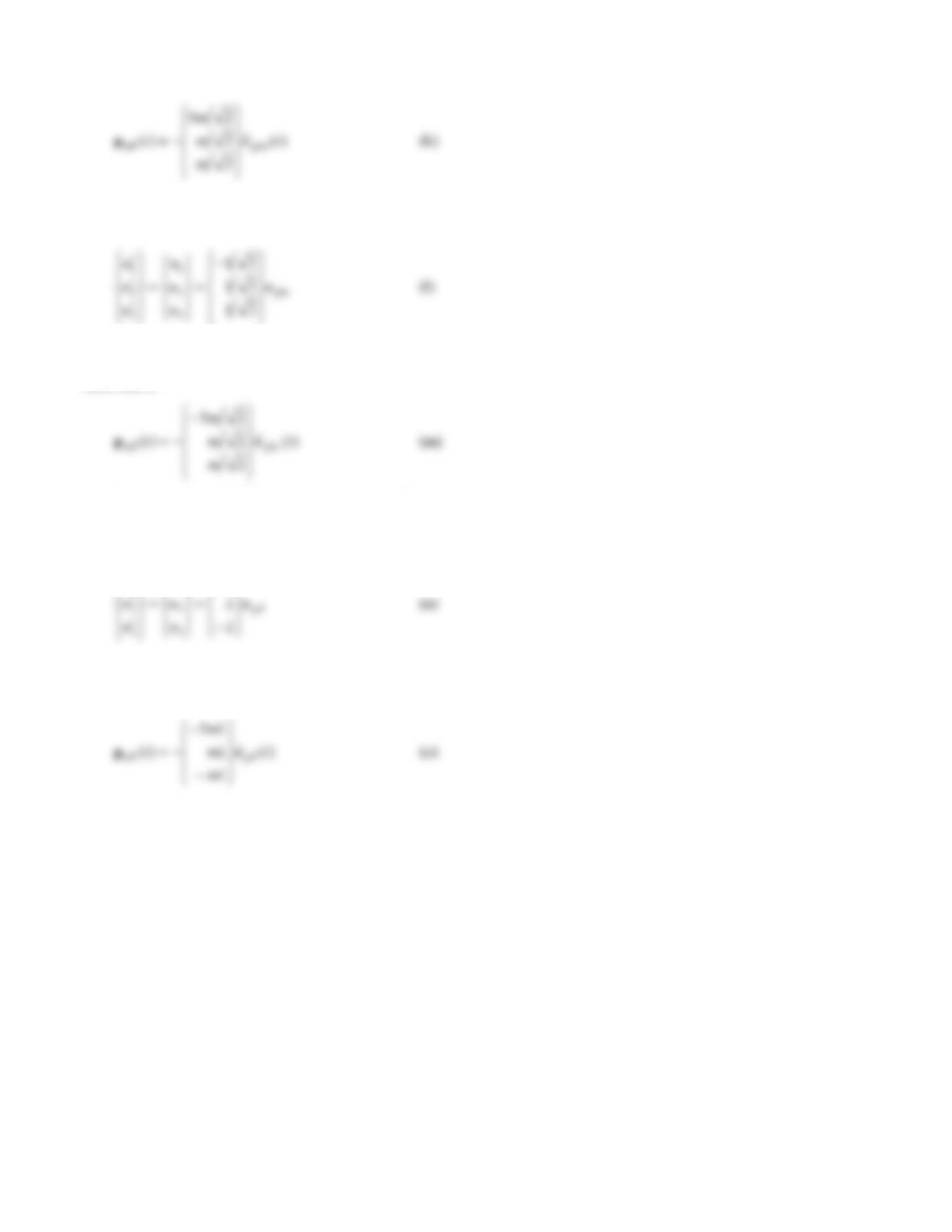
23
(iv) If the excitation is ground motion )(tugbc in the
direction b-c,
Substituting Eq. (l) into Eq. (e) gives a matrix equation
with its left hand side the same as Eq. (g) and the right
hand side is
(v) If the excitation is rocking ground motion defined by
counter-clockwise rotation
g
u(in radians) in the plane of
the structure,
t
L
u
u
1
1
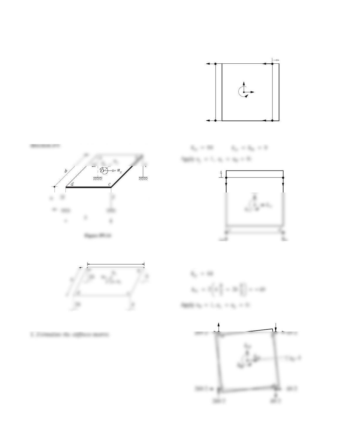
Substituting Eq. (n) into Eq. (e) gives a matrix equation
with its left hand side the same as Eq. (g) and the right
hand side is
24
Problem 9.14
Figure P9.14 shows a uniform slab supported on four
columns rigidly attached to the slab and clamped at the
base. The slab has a total mass m and is rigid in plane and
out of plane. Each column is of circular cross section, and
its second moment of cross–sectional area about any
diametrical axis is as noted. With the DOFs selected as ux,
uy, and uθ at the center of the slab, and using influence
coefficients:
(a) Formulate the mass and stiffness matrices in terms of m
and the lateral stiffness k = 12EI/h3 of the smaller column;
h is the height.
(b) Formulate the equations of motion for ground motion
in (i) the x-direction, (ii) the y-direction, and (iii) the
Solution:
k
k
b
Part a
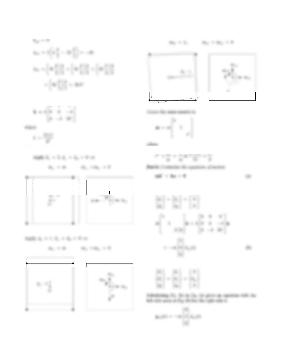
Apply u
x
1, uu
y
0:
u = 1
x
2k
2k
k
k
kyx
k
x
kxx
ab
cd
By statics,
u = 1
y
2k
2k
k
k
kyy
ab
By statics,
k
xy
0
2kb/2
kb/2
x
k
k
x
25
By statics,
Hence the stiffness matrix is
2. Formulate the mass matrix.
myx
Apply
u
1,
uu
xy
0
O
I
(i) Ground motion in the x-direction.
t
uuu
(ii) Ground motion in the y-direction.
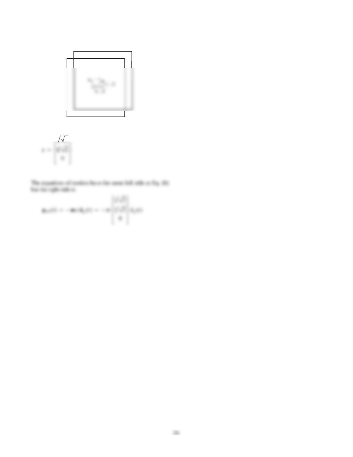
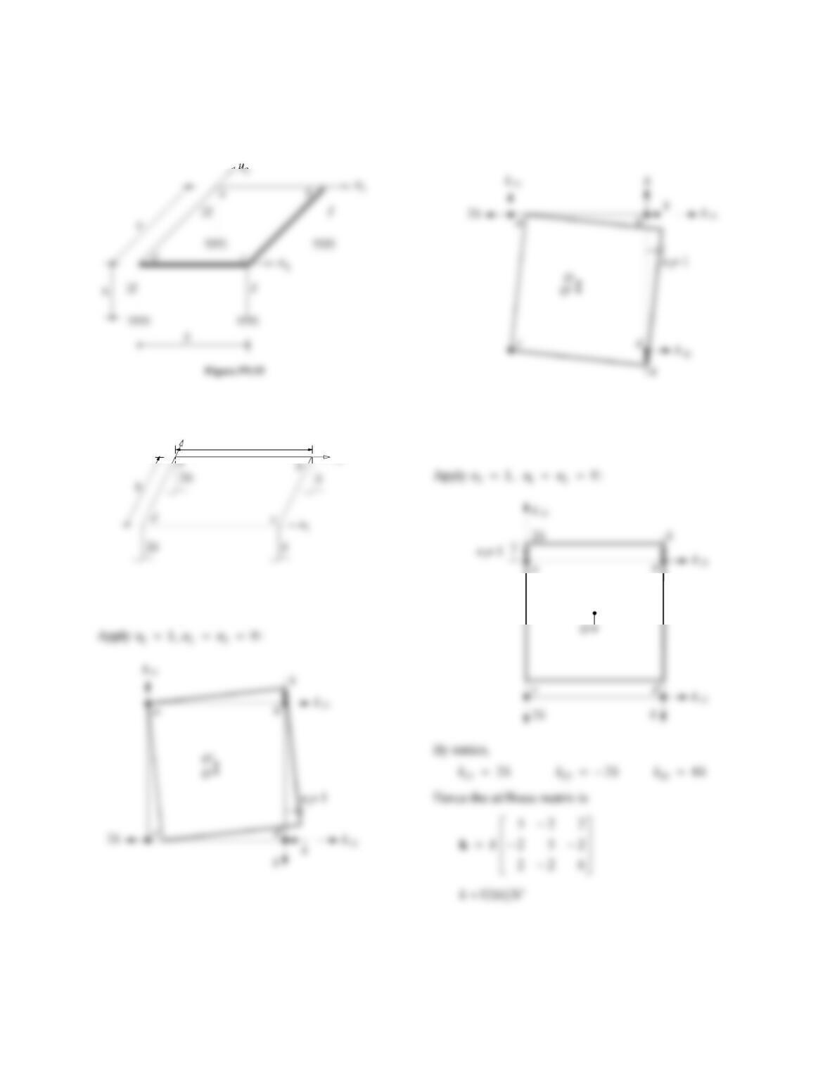
(iii) Ground motion in the d-b direction.
The influence vector is
27
Problem 9.15
Repeat Problem 9.14 using the second set of DOFs shown
in Fig. P9.15.
Solution:
u2
u3
b
Part a
1. Formulate the stiffness matrix.
k
k
k
k
k
k
By statics,
k
k
11 5
k
k
21 2
k
k
31 2
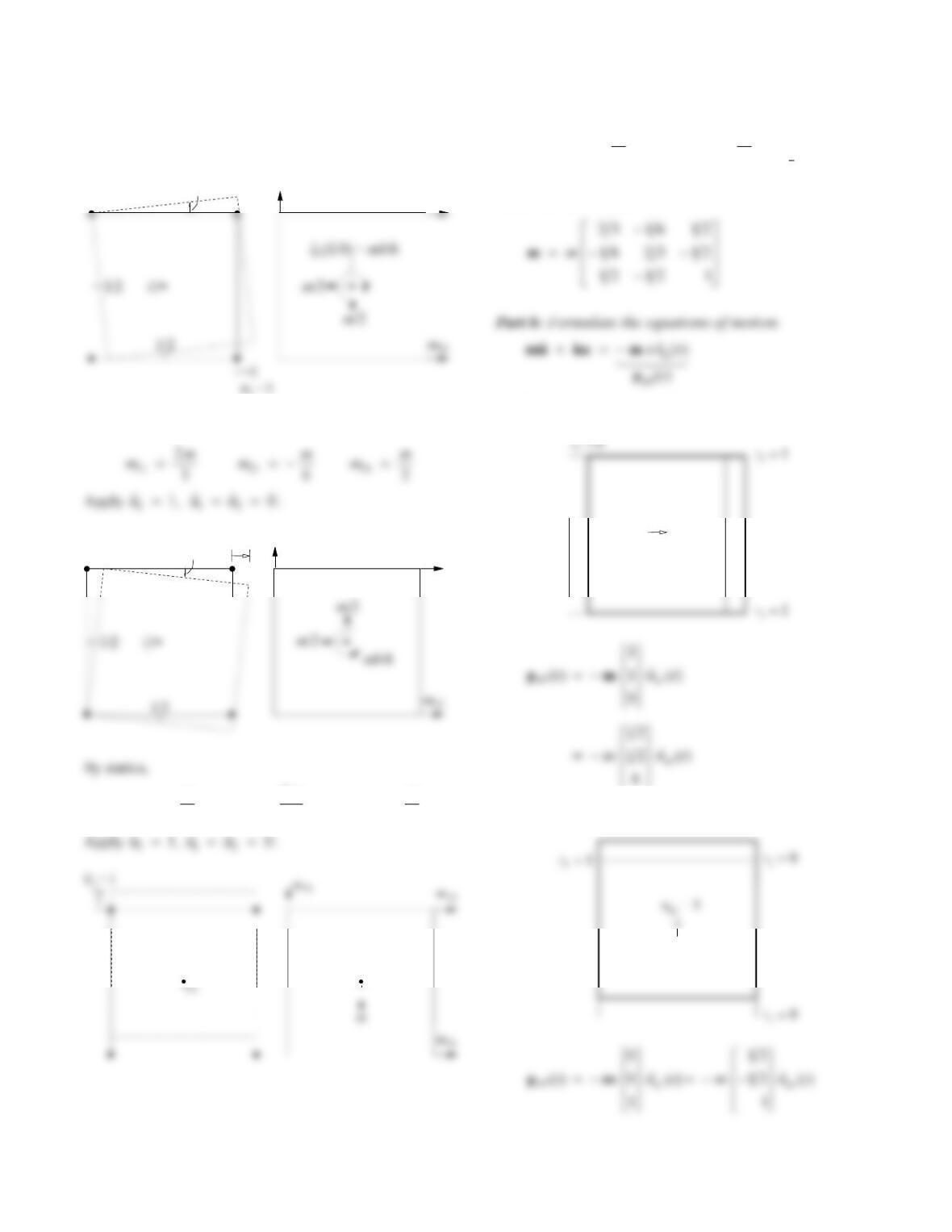
Apply 21u
, 13
0uu
:
By statics,
k
k
12 2
k
k
22 5
k
k
32 2
O’
28
2. Formulate the mass matrix.
Apply 11u
, 23
0uu
:
By statics,
mm
12 6
mm
22
2
3
mm
32 2
By statics,
mm
13 2
mm
23 2
Hence the mass matrix is
(i) Ground motion in the x-direction.
u = 1
gx
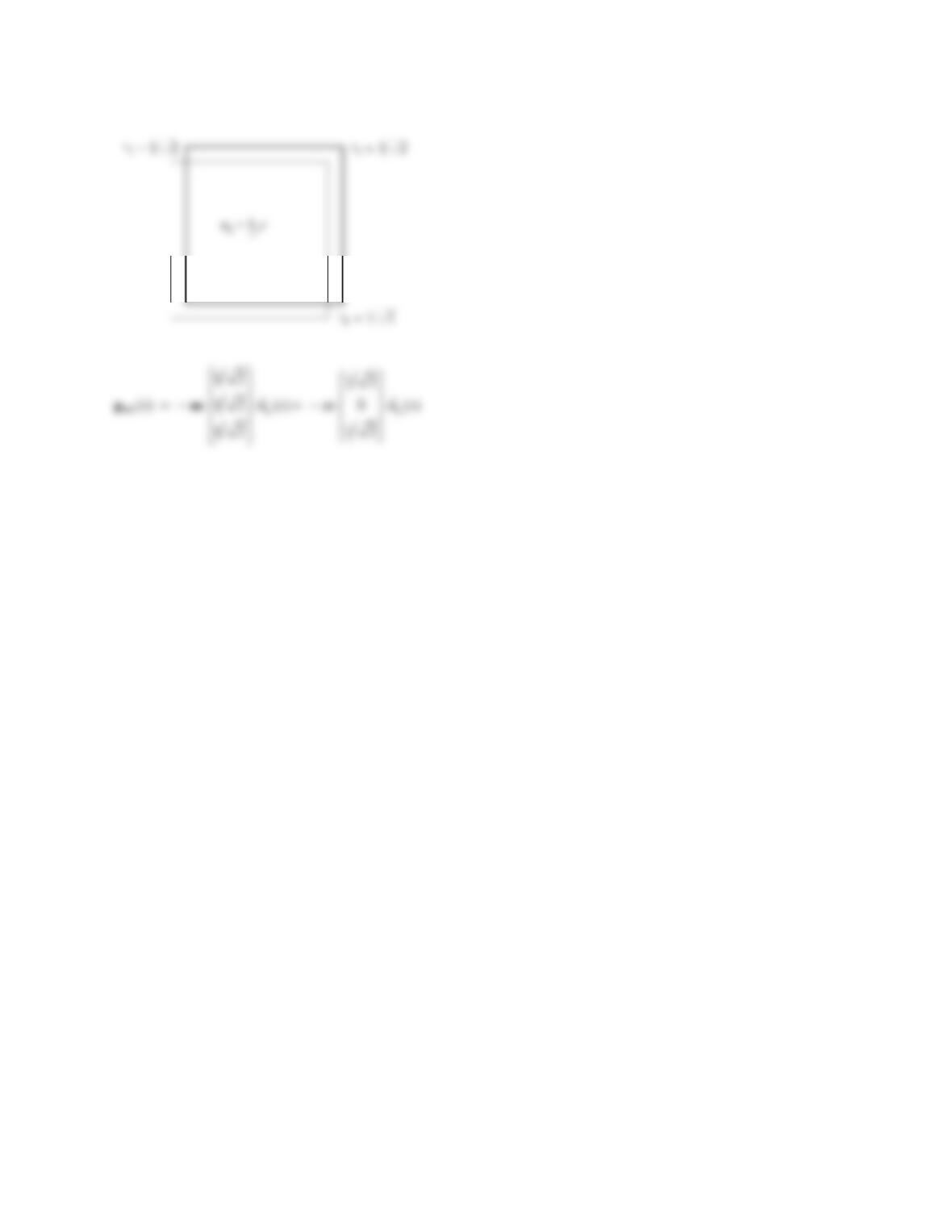
(ii) Ground motion in the y-direction.
m31
m21
1
1/b
m32 m22
u =1
2
1/b
m33 = m
29
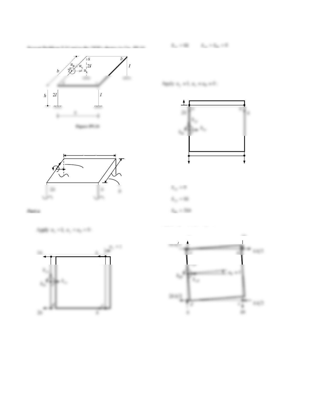
(iii) Ground motion in the d-b direction.
30
Problem 9.16
Repeat Problem 9.14 using the DOFs shown in Fig. P9.16.
Solution:
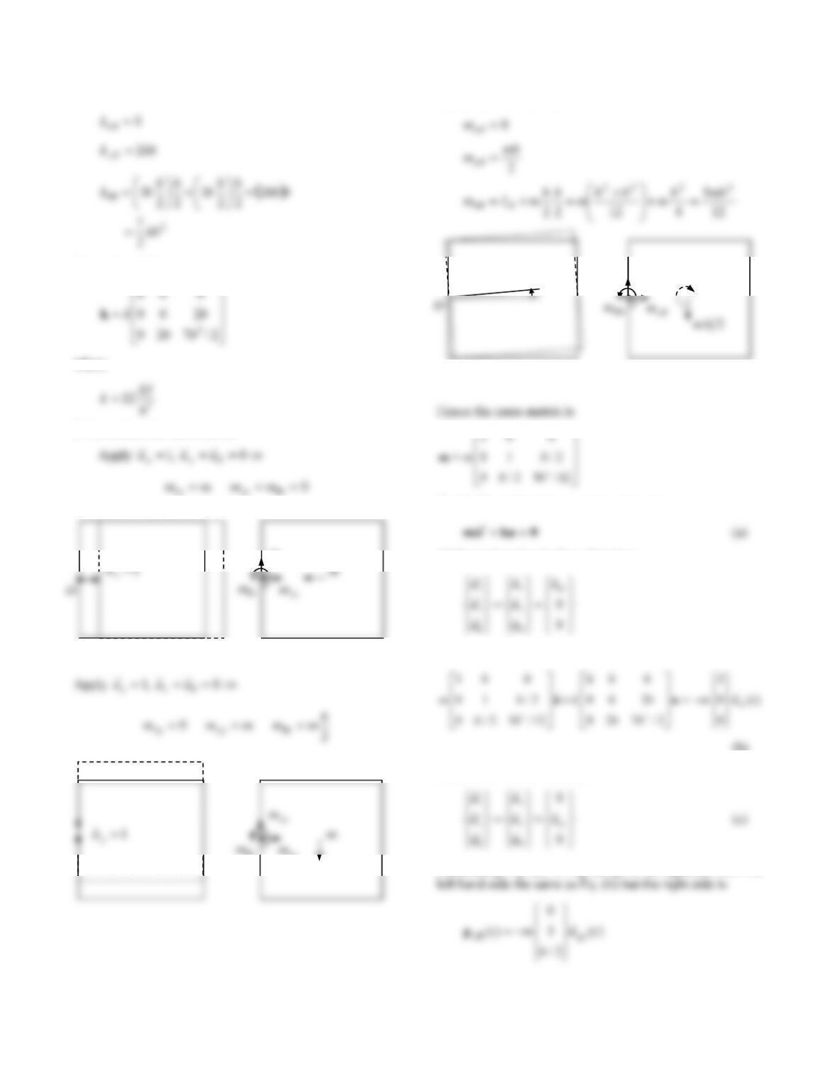
1. Formulate the stiffness matrix.
By statics,
By statics,
Apply :0 ,1 yx uuu
d
k2
k
c
1
y
u
kb
k
0
b
x
u
u
ab
c
k
k2
y
u
d
a
b
k
k
31
By statics,
Hence the stiffness matrix is
where
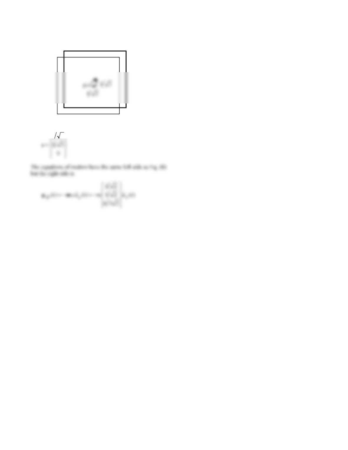
2. Formulate the mass matrix.
Apply
0 ,1 yx uuu
Part b: Formulate the equations of motion.
(i) Ground motion in the x-direction.
Substituting Eq. (b) in Eq. (a) gives
(b)
(ii) Ground motion in the y-direction.
Substituting Eq. (c) in Eq. (a) gives an equation with the
yx
m
xy
y
1
u
y
m
O
I
32
(iii) Ground motion in the d-b direction.
The influence vector is
21
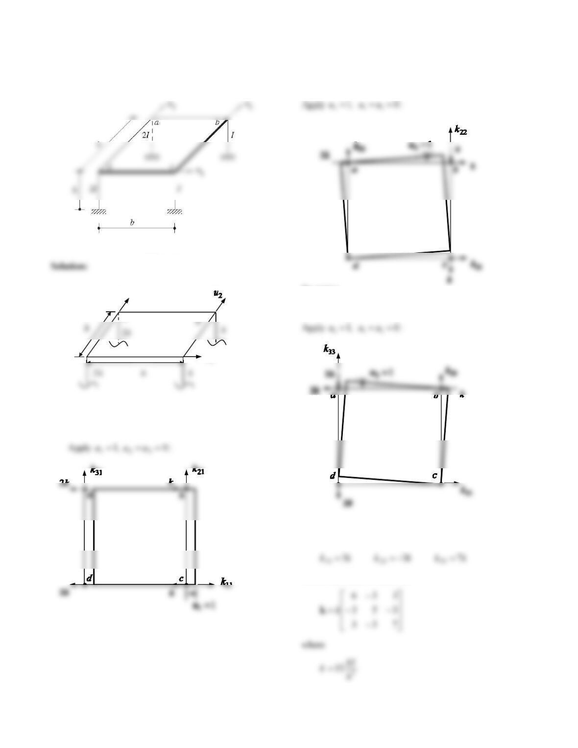
33
Problem 9.17
Repeat Problem 9.14 using the DOFs shown in Fig. P9.17.
Figure P9.17
Part a
1. Formulate the stiffness matrix.
By statics,
kkkkkk 3 3 6 312111
By statics,
kkkkkk 3 5 3 322212
By statics,
Hence the stiffness matrix is
u
ab
c
3
u
d
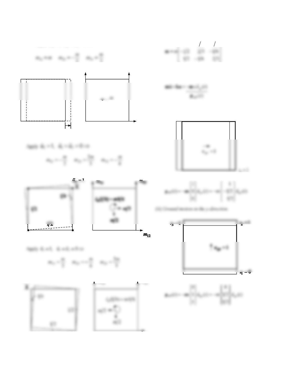
34
2. Formulate the mass matrix.
Apply 0 ,1 321 uuu
2
2
Hence the mass matrix is
21 211
Part b: Formulate the equations of motion.
(i) Ground motion in the x-direction.
1
1u
11
m
21
m
31
m
13
m
m
1
3u
1
0
2
0
3
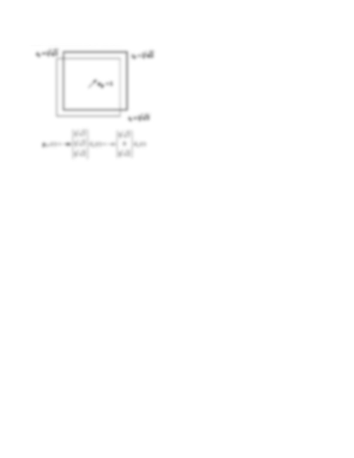
35
(iii) Ground motion in the d-b direction.
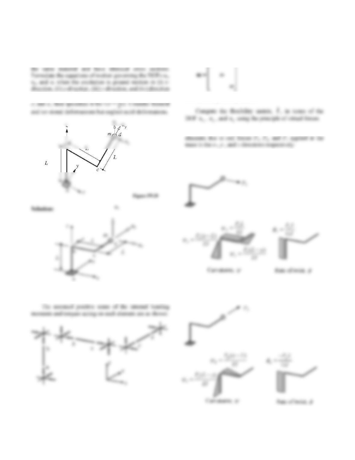
36
Problem 9.18
Figure P9.18 shows a three-dimensional pipe abcd
clamped at a with mass m at d. All members are made of
a–d. First express the flexibility matrix in terms of E, I, G,
1. Sign Convention.
2. Determine mass matrix.
The mass matrix, m, for this structure is
m
3. Determine flexibility matrix.
3.1 Establish the curvatures and rates of twist in the
(i) Apply real force Px
(ii) Apply real force Py