37
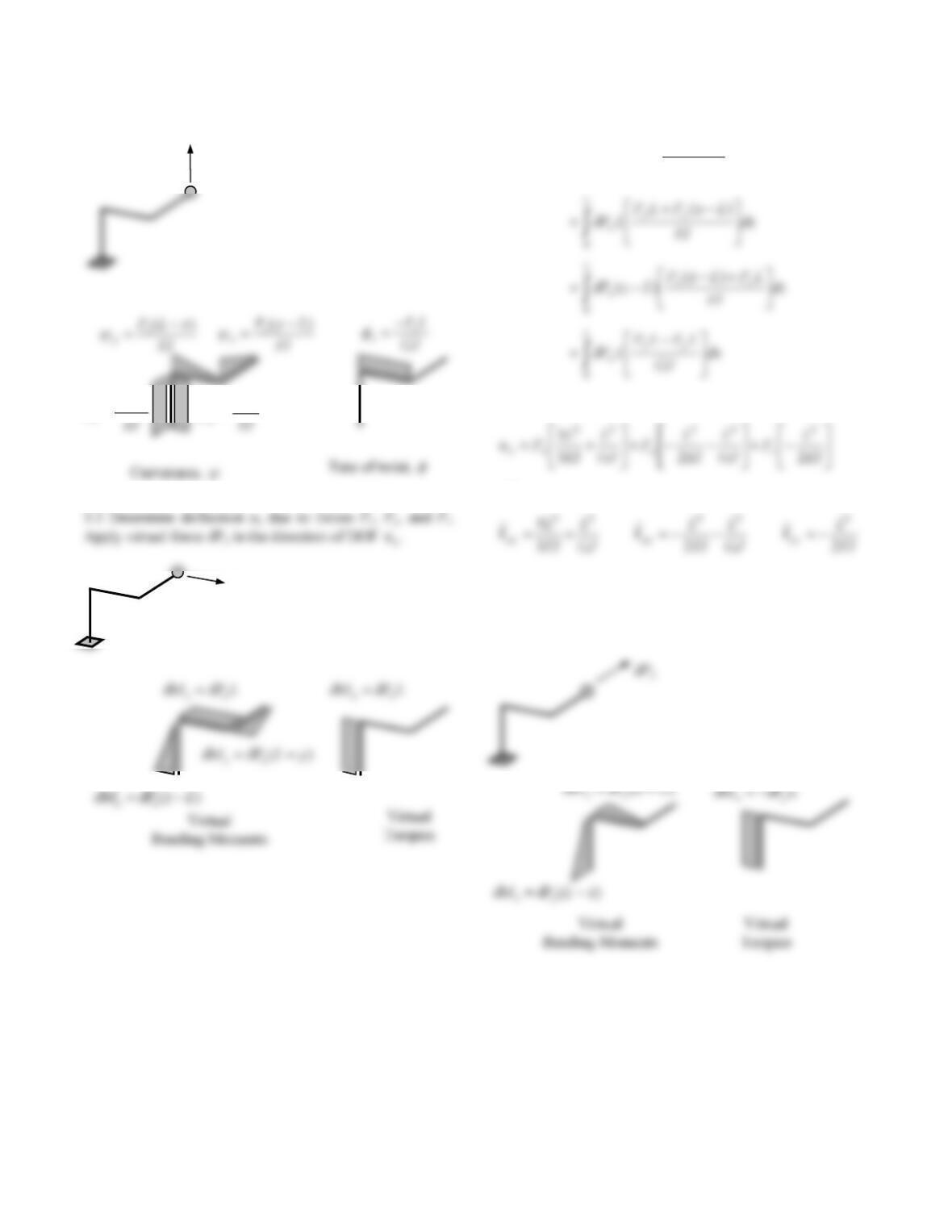
(iii) Apply real force Pz
Equate external and internal virtual work due to
Px
L
x
xxx
dy
EI
yLP
yLPuP
0
)(
)(
Hence,
and
3.3 Determine deflection uy due to forces Px, Py, and Pz.
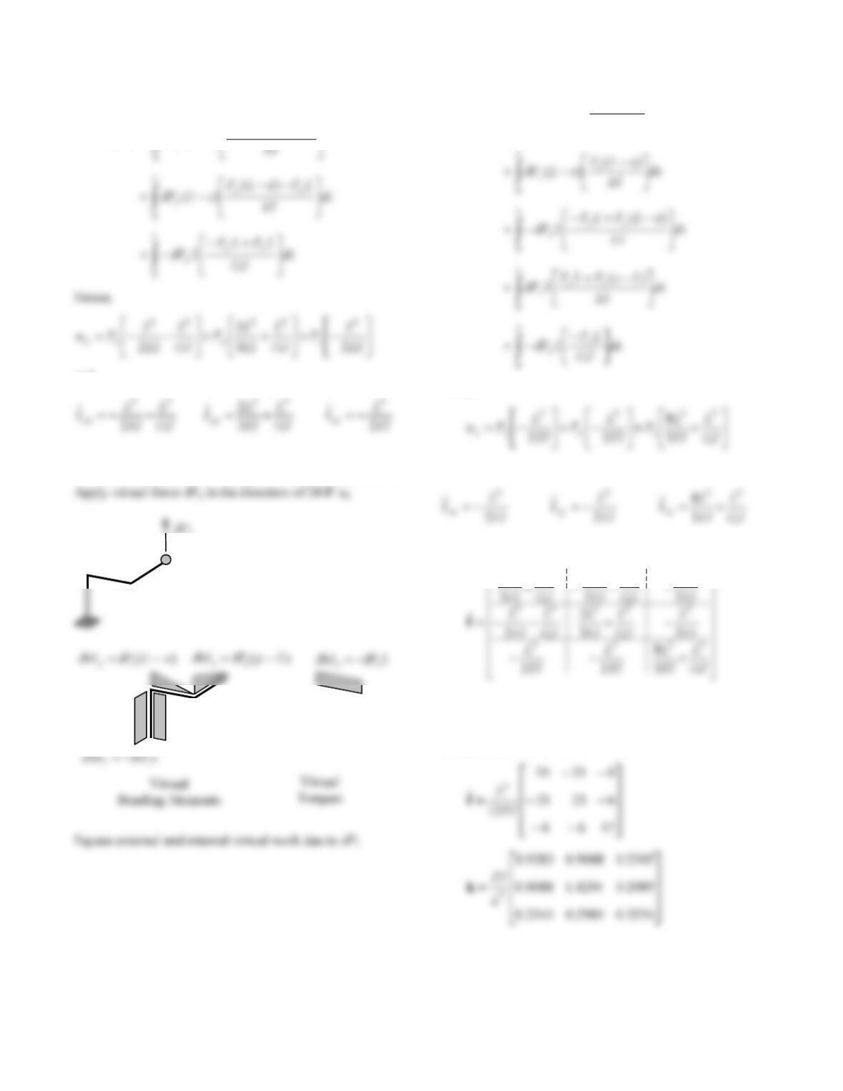
Apply virtual force
Py in the direction of DOF uy.
Px
P
z
LP
z
x
EI
LPz
y
38
Equate external and internal virtual work due to
Py
L
xy
yyy
dx
LPLxP
LxPuP
)(
)(
and
3.4 Determine deflection uz due to forces Px, Py, and Pz.
L
z
zzz
dy
EI
LyP
LyPuP
0
)(
)(
Hence,
and
Therefore the flexibility matrix, f
ˆ, is
L
L
L
L
L
33333
5
4. Determine stiffness matrix.
The stiffness matrix, k, is obtained by inverting f
ˆ. For
the case when GJ = 4/5 EI:
LPM zy
39
5. Formulate the equations of motion u = [ ux, uy, uz ]T
where m and k are given above and influence vector
= static displacements of DOF due to ug = 1.
40
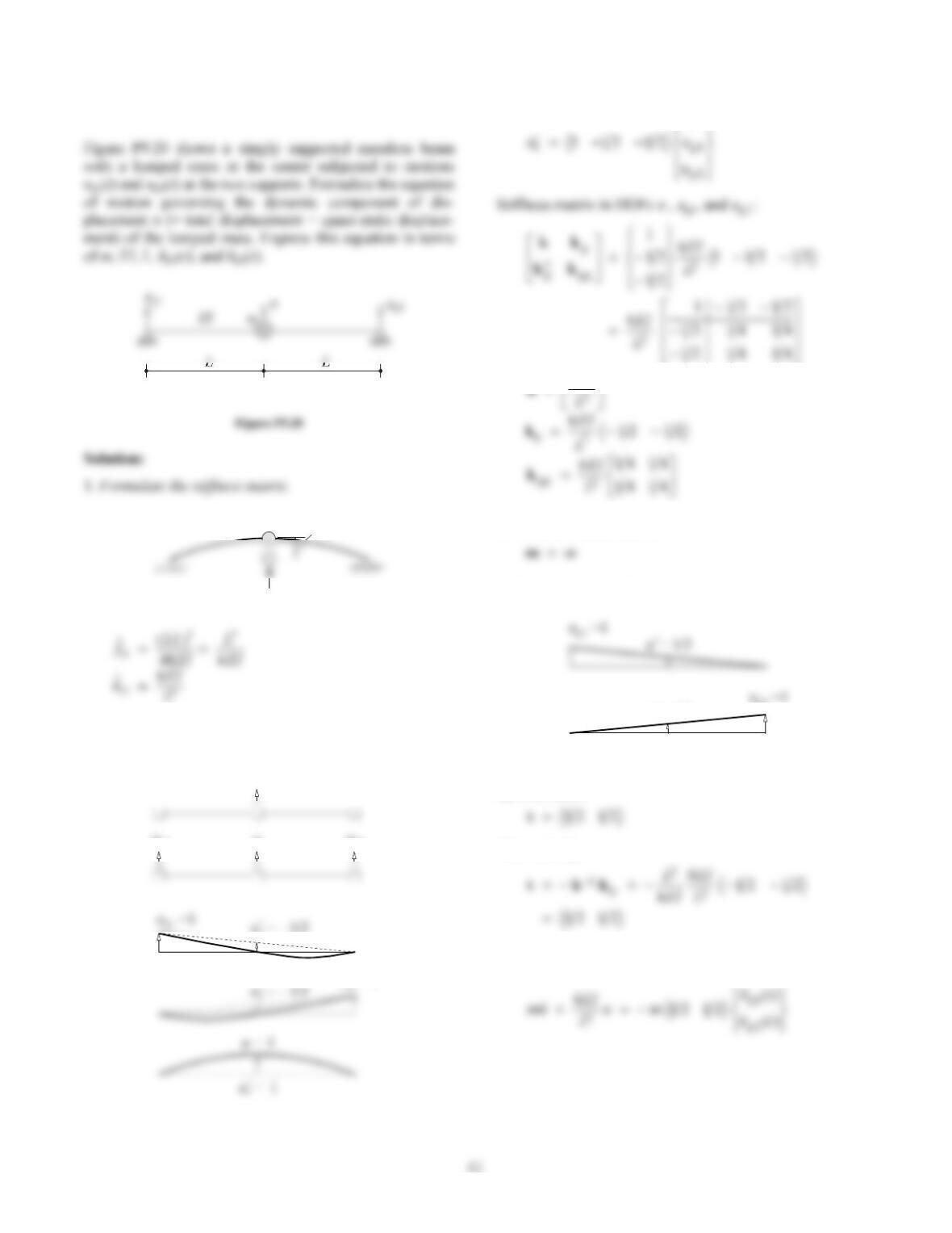
Problem 9.19
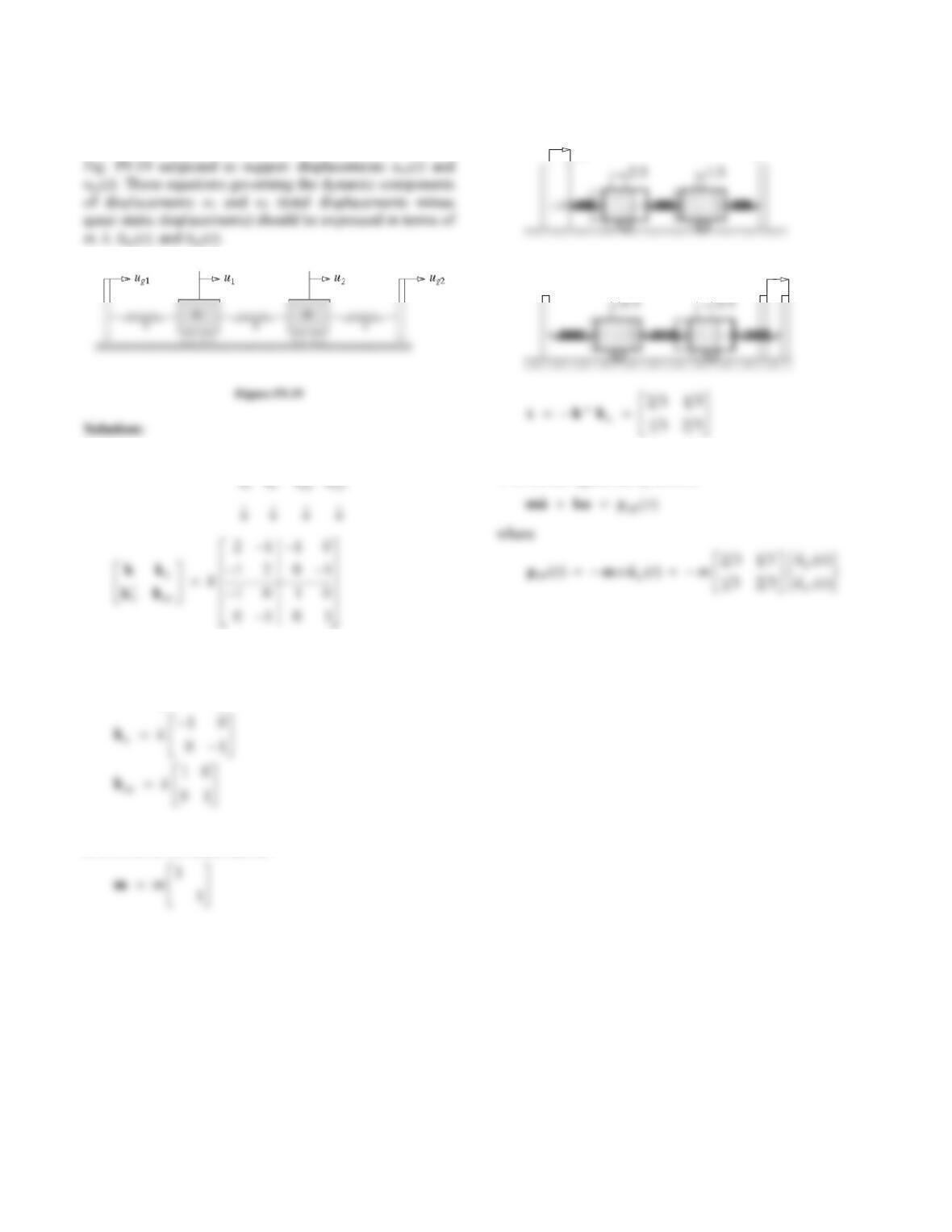
Formulate the equations of motion for the system shown in
1. Determine the stiffness matrix.
where
21
12
k
k
2. Determine the mass matrix.
3. Determine the influence matrix.
u = 1
g1
u = 0
g2
u = 0
g1
u = 1
g2
4. Write the equations of motion.
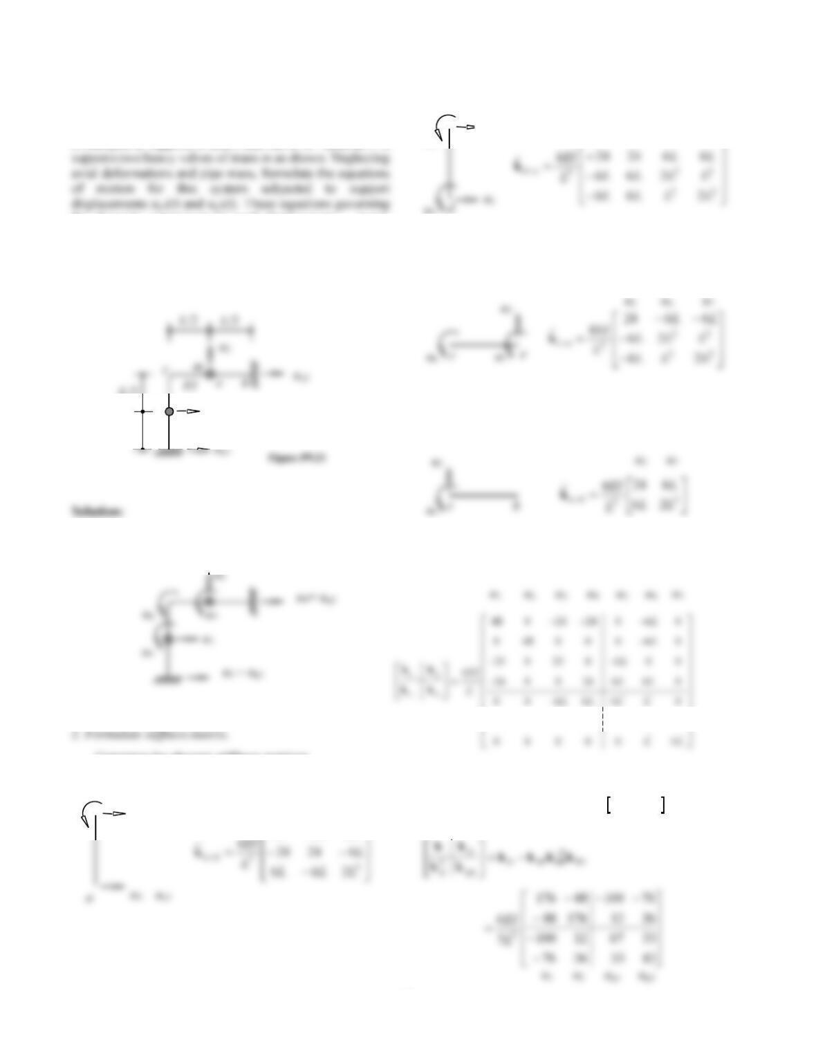
Problem 9.20
1
11
f
Coordinate transformation:
u1
u = – 1/2
1
u =1
g2
u
u
g1u
g2
u
6EI
2. Write the mass matrix.
3. Determine the influence matrix.
g2
u = 1/2
s
By kinematics
Alternatively,
4. Write the equation of motion.
42
Problem 9.21
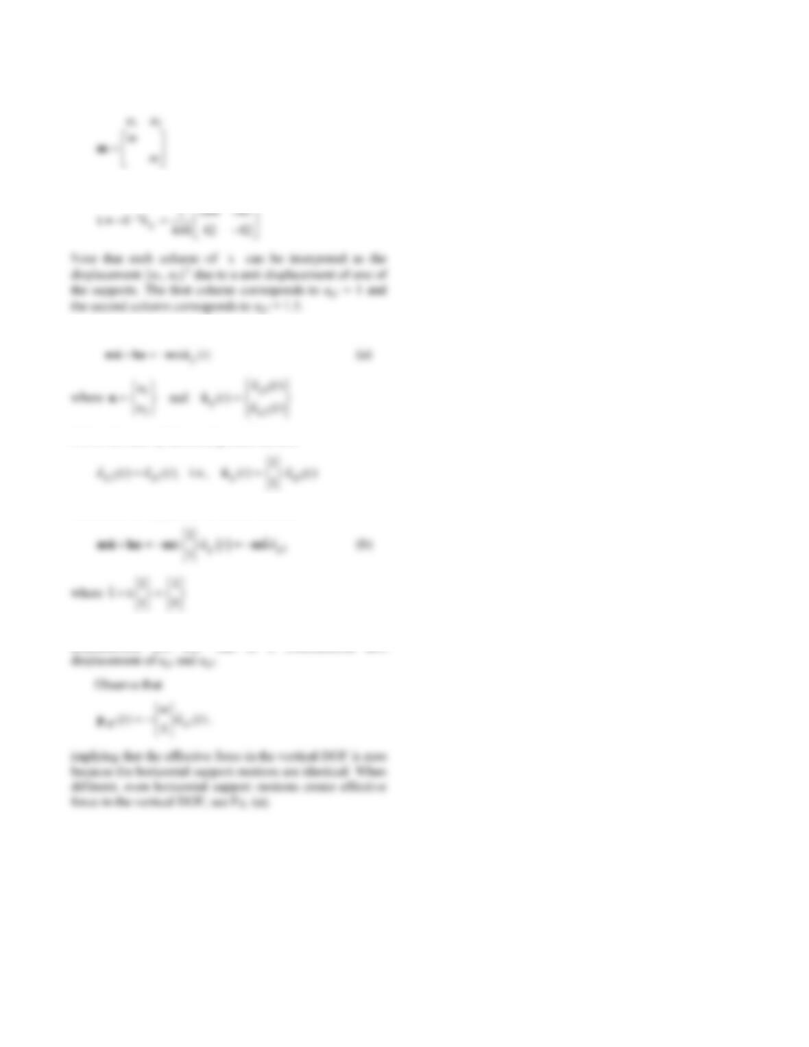
Figure P9.21 shows a pipe in an industrial plant. The pipe
is clamped at supports a and b and has a 90° bend at c. It
the dynamic component (= total displacement − quasi-
static component) of the displacements u1 and u2 should be
expressed in terms of m, EI, and L. How do these
governing equations differ from the case of identical
motion at both supports?
L
L
1. Define the degrees of freedom.
Construct the element stiffness matrices
Element a-d
Element d-c
Element c-e
Element e-b
Add element stiffness matrices into global stiffness matrix.
Condense out the rotational DOF uuuT
567
,,
u1
m
d
a
EI
L
/2
L
/2
u5
u1
62424
L
u1 u3 u5
u6
662424
LL
u1 u4 u5 u6
u5
c
d
222
6606 4
LL LL LL
u4 = ug2
43
3. Write the mass matrix.
4. Determine the influence matrix.
5. Write the equations of motion.
6. For the case of identical ground motion.
Therefore, the equations of motion become
Note that this influence vector can be interpreted as the
displacement {u1, u2}T due to a simultaneous unit
44
Problem 9.22
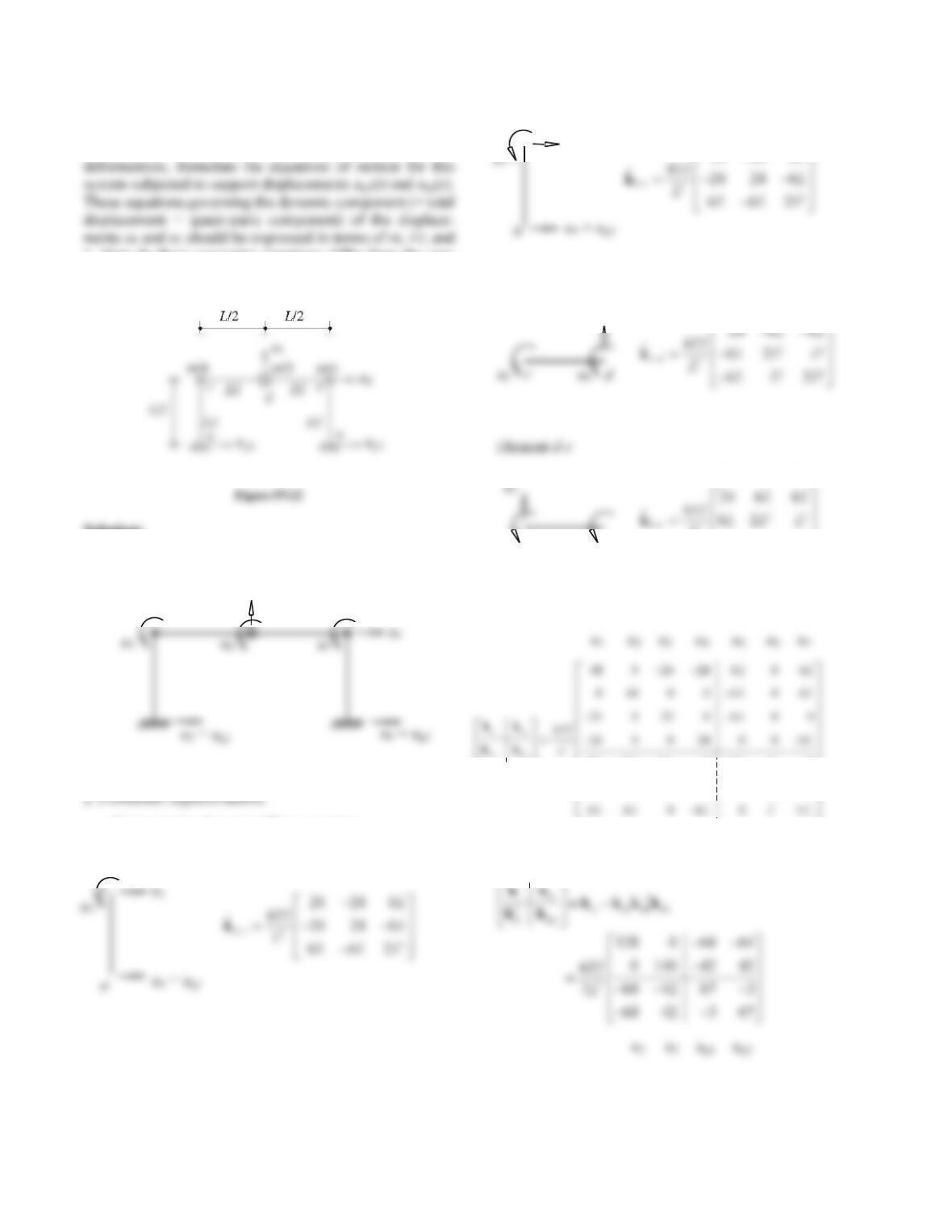
Figure P9.22 shows a single–span bridge. Neglecting axial
L. How do these governing equations differ from the case
of identical motion at both supports?
Solution:
1. Define the degrees of freedom.
L
L
L
L
Construct the element stiffness matrices
Element a-c
Element b-e
Element c-d
Add element stiffness matrices into global stiffness matrix
Condense out the rotational DOF [u5, u6, u7]T
u1 u3 u5
u2
u2 u5 u6
22
22 2
666 04 0
0000 4
t
L
LL
u2
u7
u6
3
22
62
LLL L
u2 u6 u7
de
u1
u1 u4 u7
e
24 24 6
L
45
3. Write the mass matrix.
4. Determine the influence matrix.
5. Write the equations of motion.
gtmu ku m u
(a)
6. For the case of identical ground motion.
Therefore, the equations of motion become
Note that this influence matrix can be interpreted as the
Observe that
46
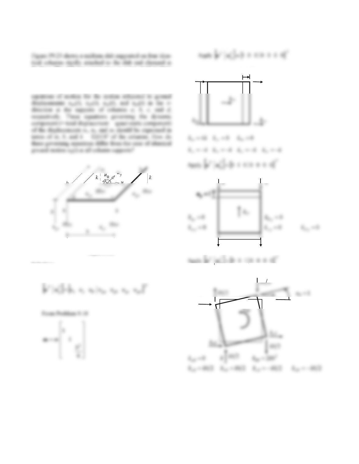
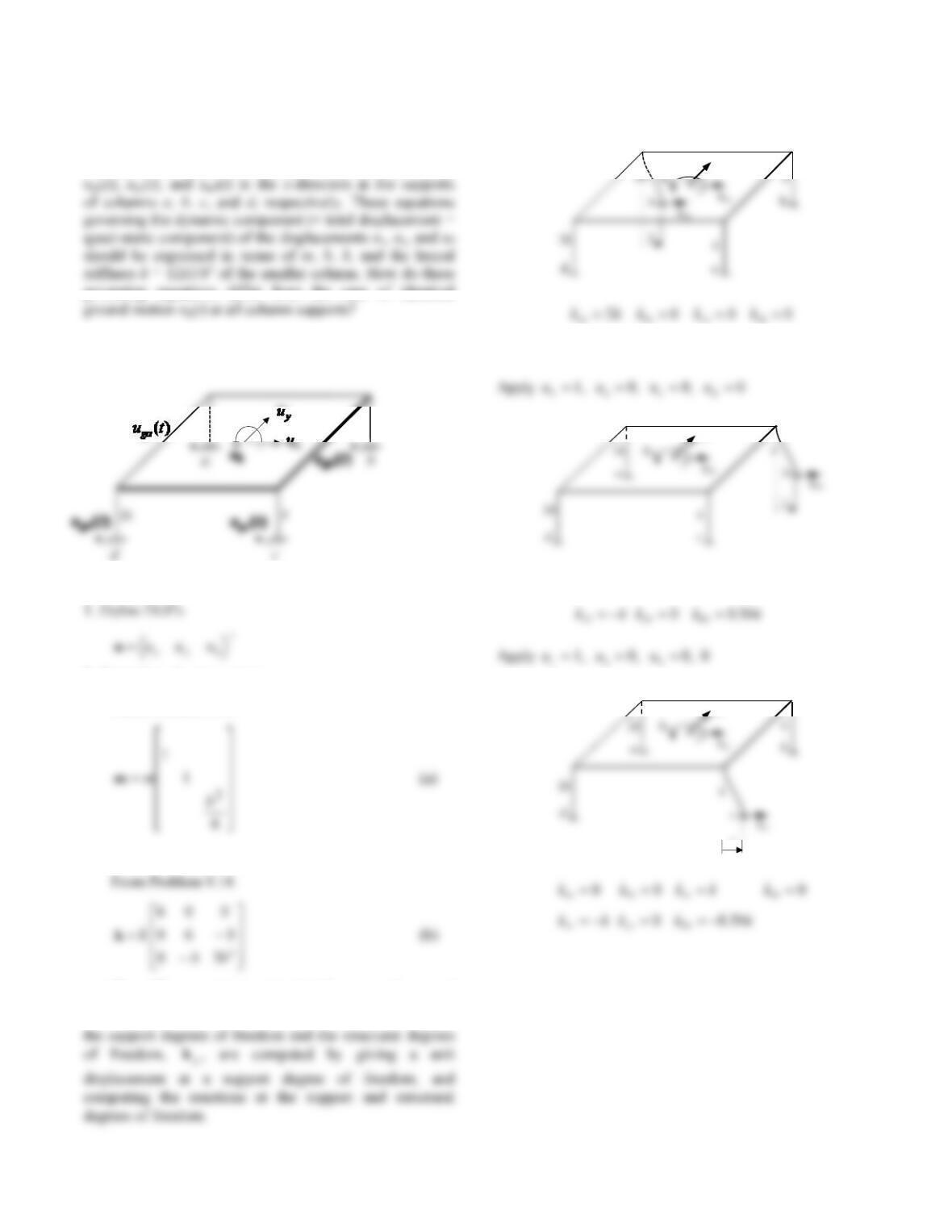
Problem 9.23
the base. The slab has a total mass m and is rigid in plane
and out of plane. Each column is of circular cross section,
and its stiffness about any diametrical axis is as noted.
With the DOFs selected as ux, uy, and uθ, formulate the
Figure P9.23
Solution:
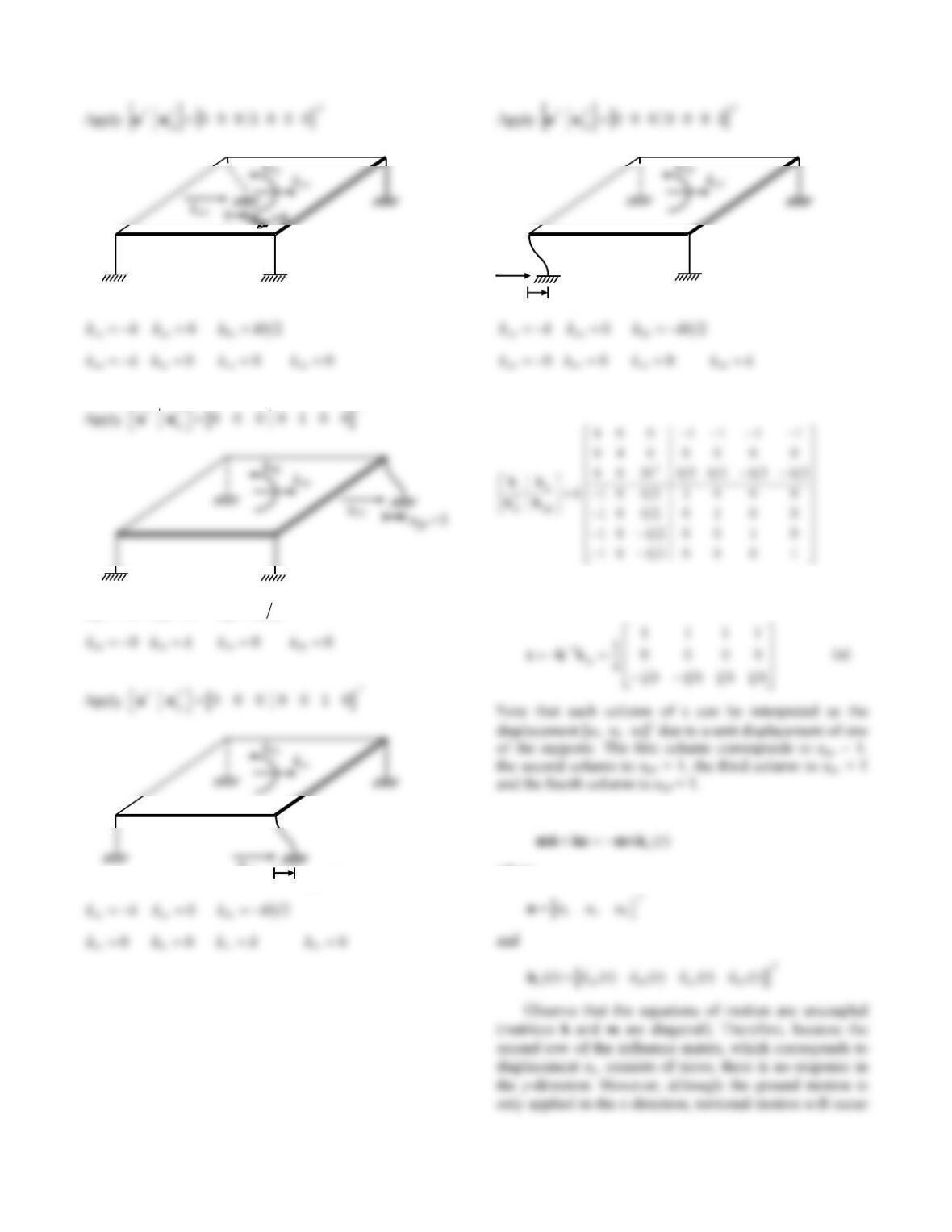
1. Define the degrees of freedom.
2. Formulate mass matrix.
3. Formulate stiffness matrix.
g
1
x
u
kbx
k
k
kax
ka
kb
47
02
xb yb b
kkk kkb
Assemble the stiffness influence coefficients
4. Determine the influence matrix.
5. Write the equations of motion.
where
1
gc
u
kcc
1
gd
u
kdd
48
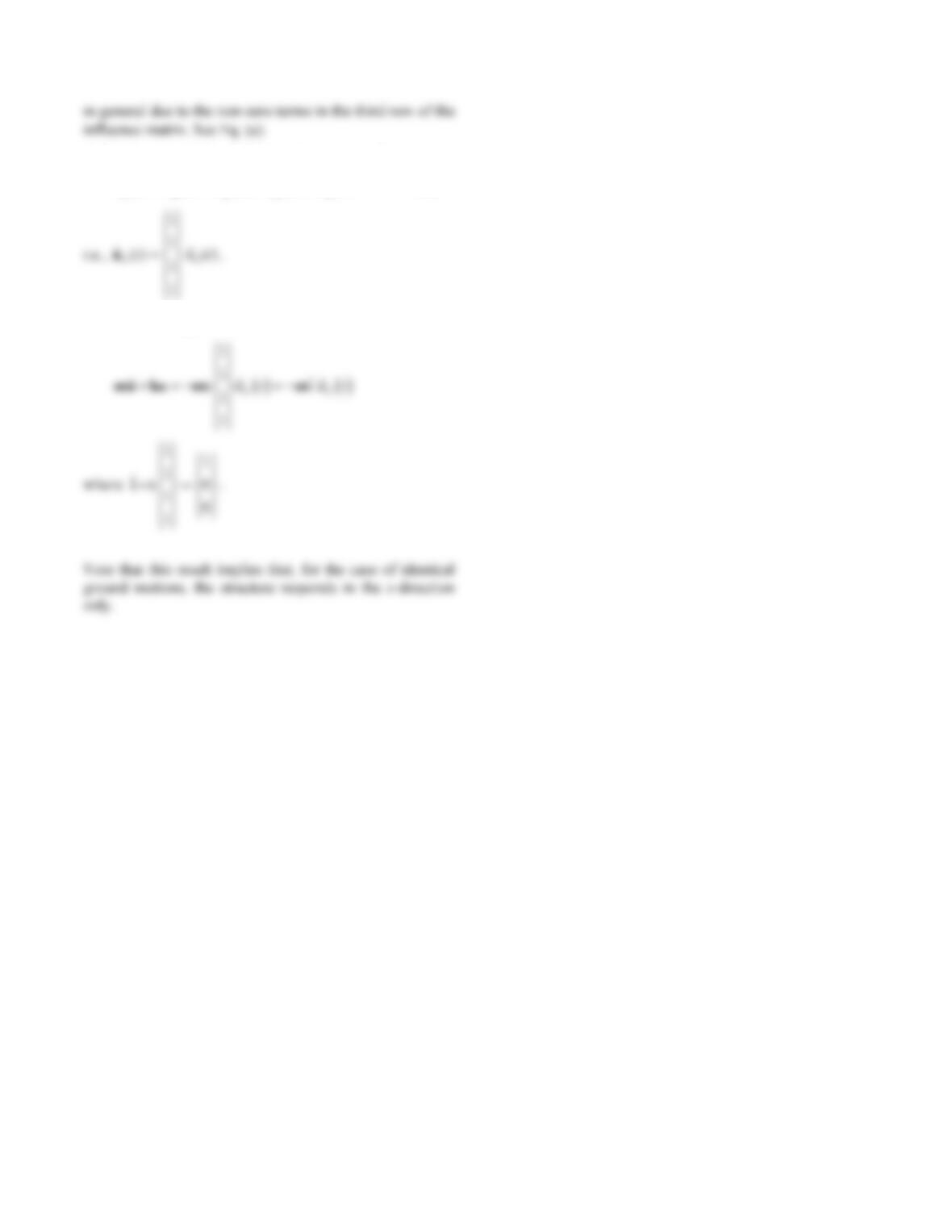
6. For the case of identical ground motion at all supports.
() () () () ()
ga gb gc gd g
ut ut ut ut ut
(e)
Therefore, the equations of motion become
49
Problem 9.24
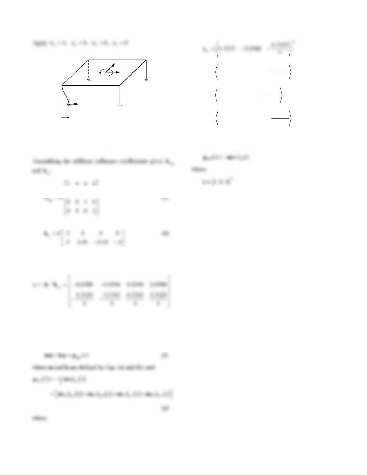
Formulate the equations of motion for the system of
Problem 9.14 subjected to ground displacements uga(t),
governing equations differ from the case of identical
Solution:
2. Formulate the mass matrix.
From Problem 9.14:
3. Formulate the stiffness matrix.
The stiffness matrix associated with support degrees of
freedom, kgg , and the coupling stiffness matrix between
Apply 1
a
u
, 0
b
u
, 0
c
u, 0
d
u
k
ya
20
xa ya a
kkk kbk
k
yb
000
ab bb cb db
kkkkk
1
k
yc
k
2k
50
d
b
c
1
2k
k
k
2k
k
c
k
xc
k
yc
k
dd
a
0002
20
ad bd cd dd
xd yd d
kkkkk
kkk kbk
0010
0002
2112
4. Determine the influence matrix.
3333.01667.01667.03333.0
(e)
5. Formulate the equations of motion.
The dynamic components of the displacements are
governed by
T
bb
1765.0
0294.01667.0
T
cb
1765.0
0294.01667.0
T
db
3529.0
0588.03333.0
6. Special case: Identical support motions.
Equation (f) applies with
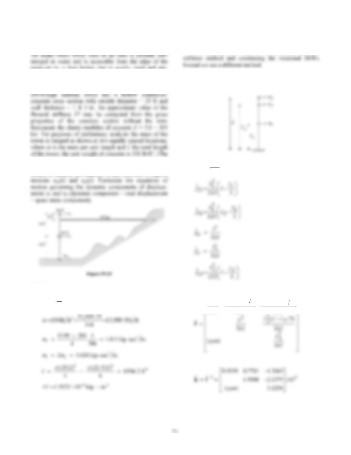
Problem 9.25
reservoir by a foot bridge that is axially rigid and pin-
connected to the tower (Fig. P9.25). (In practice, sliding is
usually permitted at the connection. The pin connection
has been used here only for this hypothetical problem.) The
added mass of the surrounding water may be neglected
here, but it should be considered in practical analysis.) It is
desired to analyze the response of this structure to support
I
I
Solution:
22 2
(25) (22.5) 13, 430.31 in.
4
A
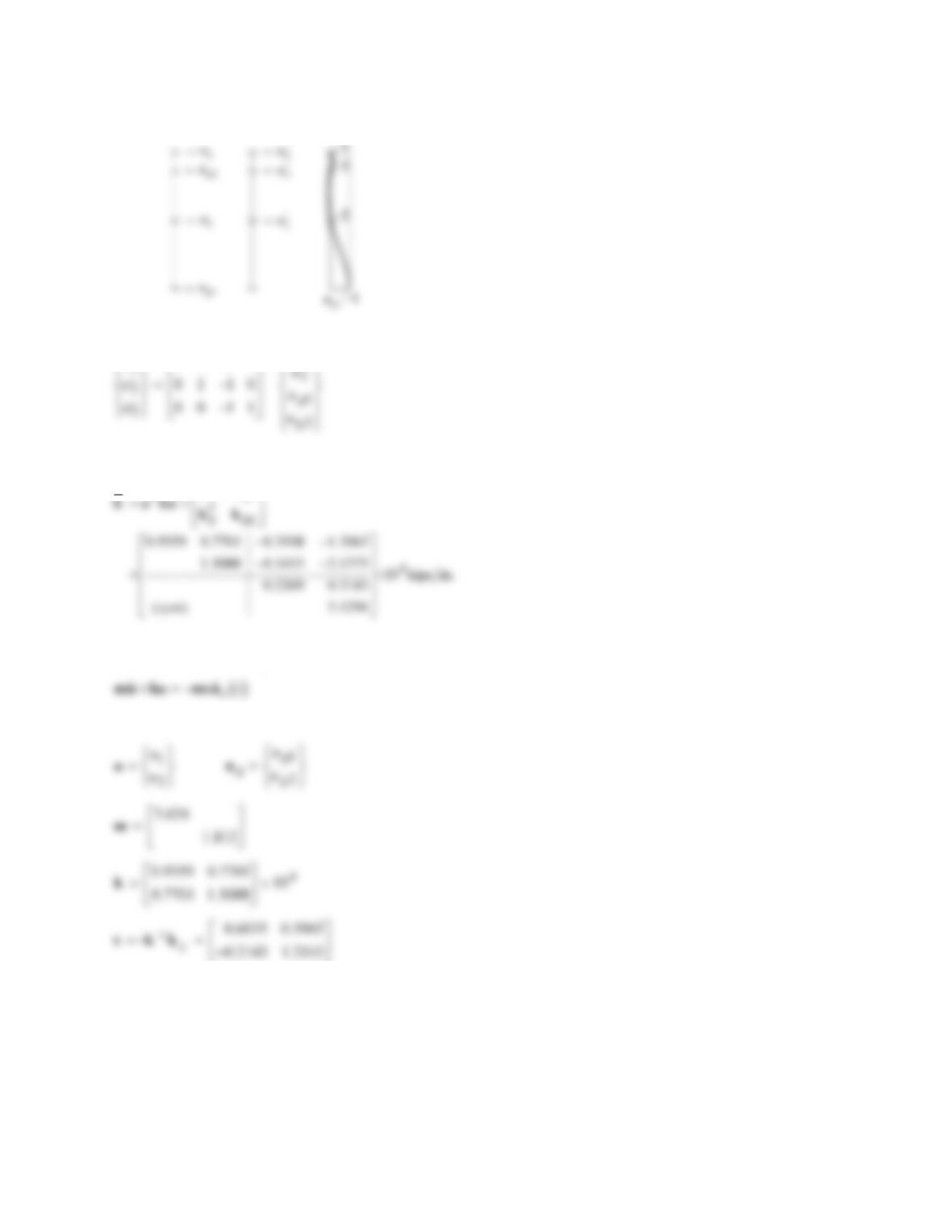
1. Formulate the stiffness matrix.
The stiffness matrix can be formulated by the direct
We use the flexibility approach to determine
k for
DOFs u1, u2, and u3:
fL
E
I
11 1
3
3
EI
LLL
EI
LLL
EI
L
2
)3(
2
)3(
3
12
2
1
1
2
1
3
1
52
Define the following transformation:
1
1
0101
u
u
a
The stiffness matrix in DOFs u1, u2, ug1, and ug2 is
g
kk
2. Formulate the equations of motion.
where