PROBLEM 9.57 (Cont.)
(d) From hydrostatic considerations and the assumption of a constant density ρm, the balance between the
gravitational and net pressure forces may be expressed as dp/dz = –ρm(g/gc). The momentum equation is
then of the form
or, from the known temperature distribution,
( )( )
( )
( )
22
z m c s,1 s,2
d v dx 2 g g T T x L
βρ µ
= −
<
(e) Integrating the foregiong expression, we obtain
COMMENTS: The validity of assuming fully-developed conditions improves with increasing plate
length and would be satisfied precisely for infinite plates.
PROBLEM 9.58
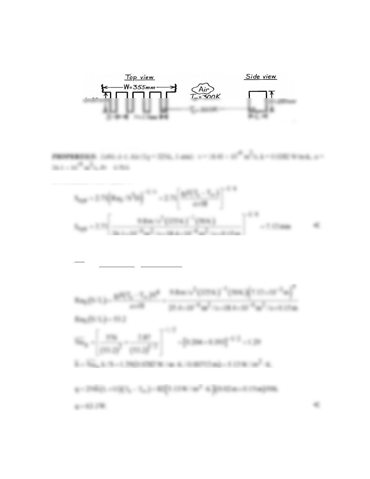
KNOWN: Dimensions of vertical rectangular fins. Temperature of fins and quiescent air.
FIND: Optimum fin spacing and corresponding fin heat transfer rate.
SCHEMATIC:
ASSUMPTIONS: (1) Isothermal fins, (2) Negligible radiation, (3) Quiescent air, (4) Negligible heat
transfer from fin tips, (5) Negligible radiation.
ANALYSIS: From Table 9.4
26.1 10 m / s 18.4 10 m / s 0.15 m
××××
From Eq. 9.45 and Table 9.4
( ) ( )
s
1/2
2 1/2
SS
576 2.87
Nu
Ra S/ L Ra S/ L
−
= +
S
With N = W/(t + S) = (355 mm)/(8.62 × 10-3 m) = 41.2 ≈ 41,
COMMENTS: Sopt = 7.12 mm is considerably less than the value of 34 mm predicted from
previous considerations. Hence, the corresponding value of q = 63.1 W is considerably larger than
that of the previous prediction.
PROBLEM 9.59
KNOWN: Length, width and spacing of vertical circuit boards. Maximum allowable board
temperature.
FIND: Maximum allowable power dissipation per board.
SCHEMATIC:
ASSUMPTIONS: (1) Circuit boards are flat with uniform heat flux at each surface, (2) Negligible
radiation.
ANALYSIS: From Eqs. 9.41 and 9.46 and Table 9.4,
A trial–and-error solution yields
2
s
q 287 W / m .
′′ =
Hence,
( )
()
22
ss
q 2A q 2 0.4 m 287 W / m 91.8 W.
′′
= = =
<
COMMENTS: Larger heat rates may be achieved by using a fan to superimpose a forced flow on the
buoyancy driven flow.
PROBLEM 9.60
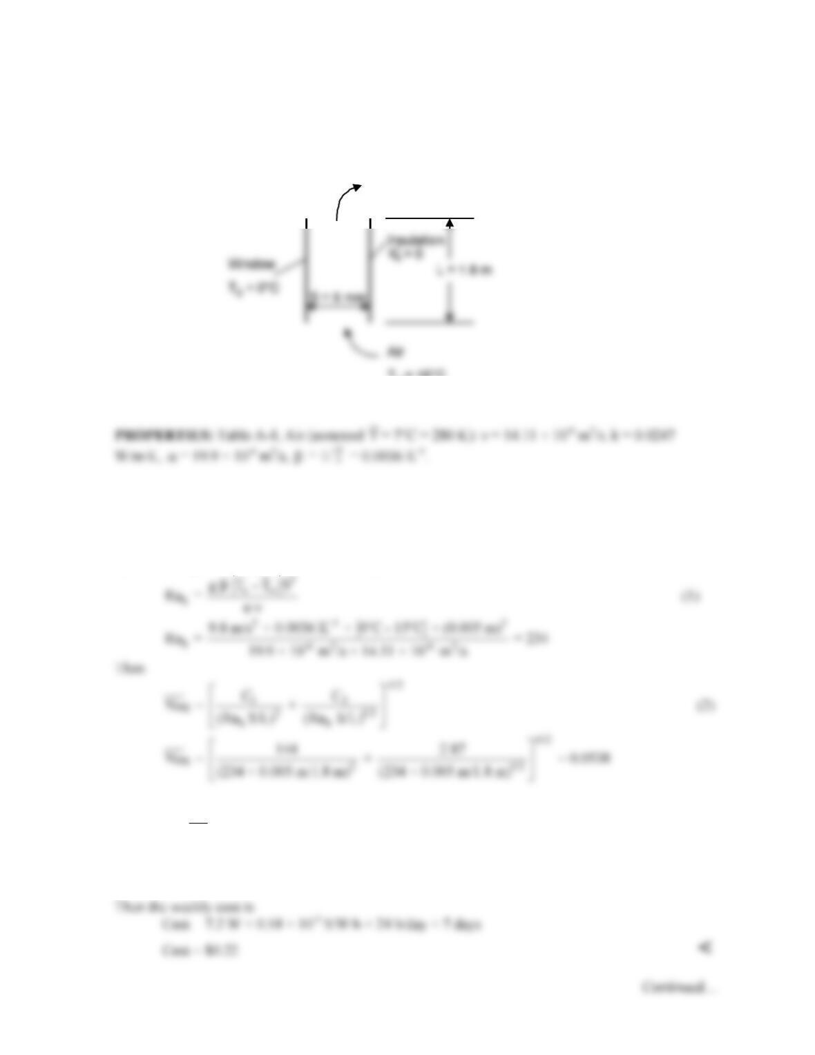
KNOWN: Dimensions of window and gap between window and insulation. Temperature of window
and surrounding air.
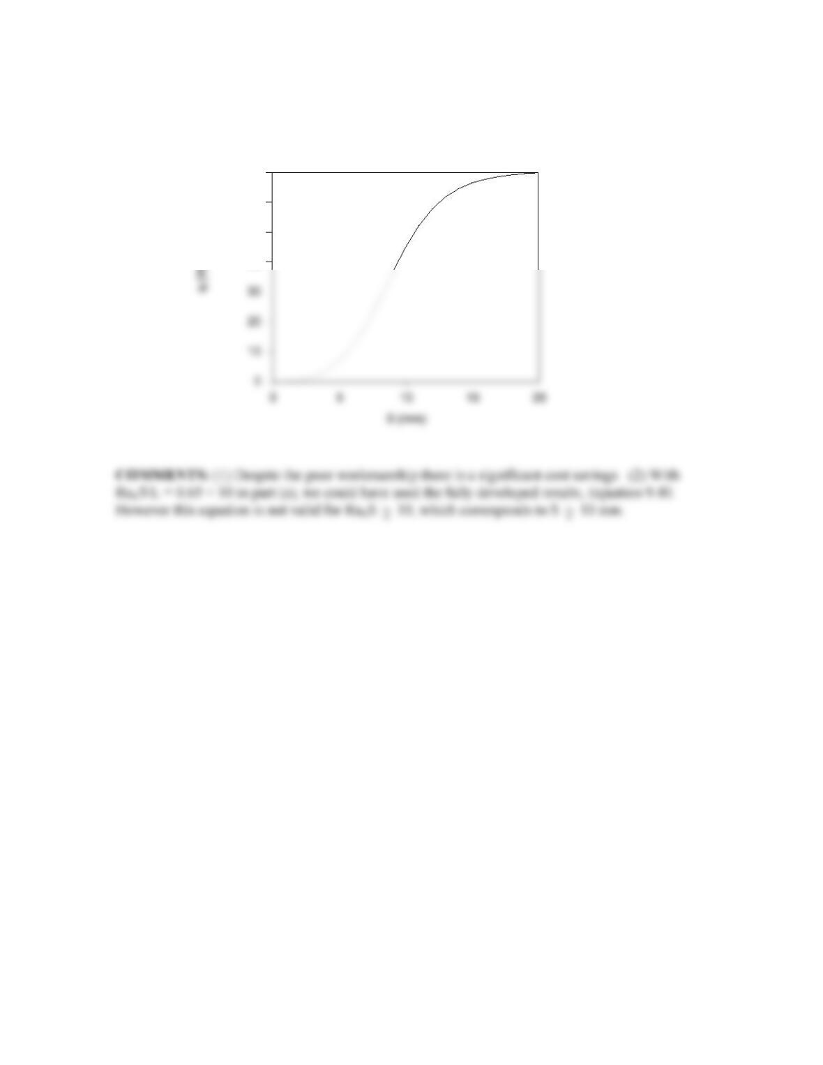
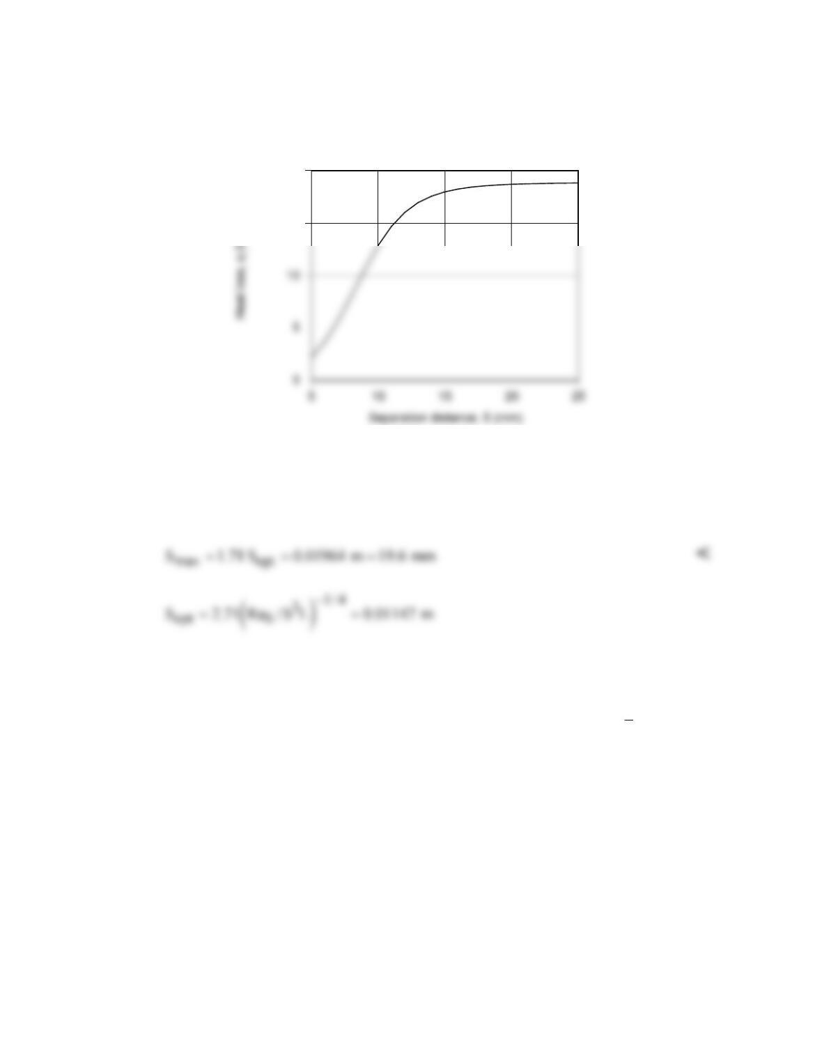
FIND: (a) Rate of heat loss through the window and associated weekly cost, (b) Rate of heat loss
through window as a function of gap spacing.
SCHEMATIC:
ASSUMPTIONS: (1) Negligible radiation heat loss. (2) Insulation creates adiabatic condition.
ANALYSIS:
(a) This is a case of free convection in a vertical parallel plate channel. The window can be
approximated as isothermal and the insulation can be modeled as adiabatic. Therefore we can use
Equation 9.45 to find the average Nusselt number, with C1 = 144, C2 = 2.87 in Table 9.4. We begin
by calculating the Rayleigh number from Equation 9.38:
From Equation 9.37 (noting that heat transfer is in the direction from the air to the surface)
SS
q = Nu k A (T – T )/S
∞
(3)
2
= 0.0538 × 0.0247 W/m K × 1.8 m (15°C – 0°C)/0.005 m ⋅
= 7.2 W
<
T
∞
= 15°C
T
∞
= 15°C
T
∞
= 15°C
PROBLEM 9.60 (Cont.)
(b) Solving Equations (1), (2), and (3) for 1 mm ≤ S ≤ 20 mm, the following graph can be generated.
40
50
60
70
PROBLEM 9.61
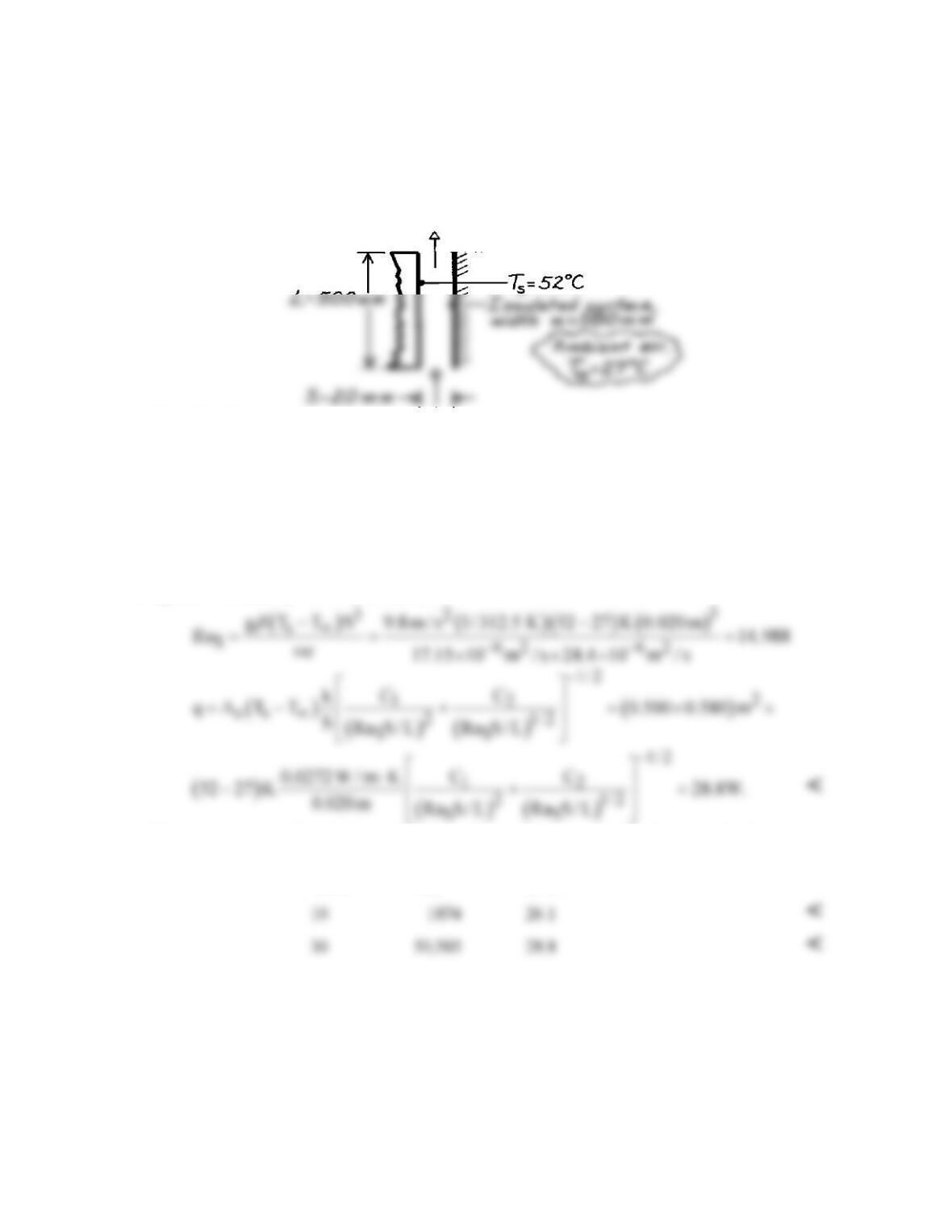
KNOWN: Vertical air vent in front door of dishwasher with prescribed width and height. Spacing
between isothermal and insulated surface of 20 mm.
FIND: (a) Rate of heat loss from the tub surface and (b) Effect on heat rate of changing spacing by ±
10 mm.
SCHEMATIC:
ASSUMPTIONS: (1) Steady-state conditions, (2) Vent forms vertical parallel isothermal/adiabatic
plates, (3) Ambient air is quiescent.
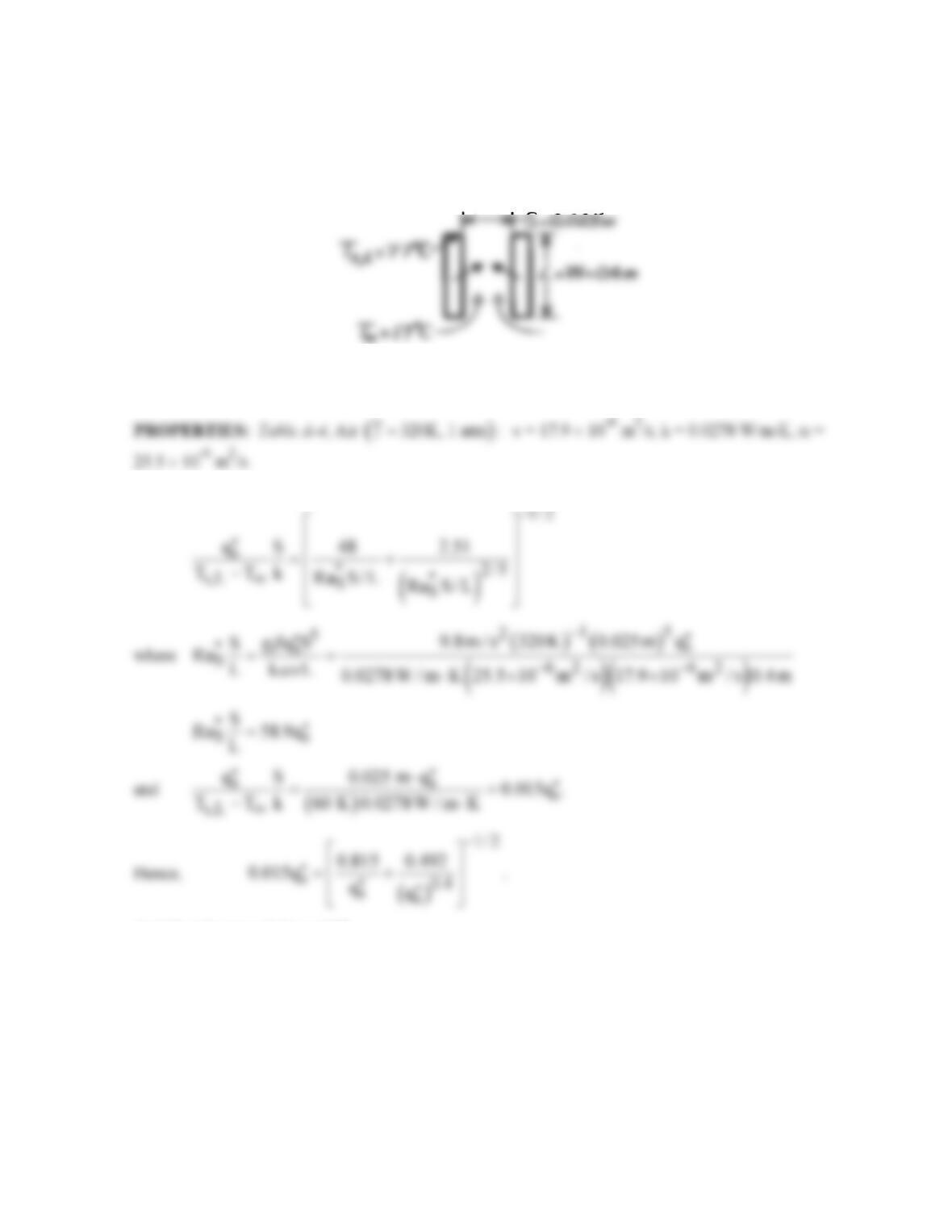
PROPERTIES: Table A-4, (Tf = (Ts + T∞)/2 = 312.5K, 1 atm): ν = 17.15 × 10⁻⁶ m2/s, a = 24.4 ×
10-6 m2/s, k = 27.2 × 10⁻³ W/m⋅K, β = 1/Tf.
ANALYSIS: The vent arrangement forms two vertical plates, one is isothermal, Ts, and the other is
adiabatic
( )
q 0.
′′ =
The heat loss rate can be estimated from Eq. 9.37 with the correlation of Eq. 9.45
using C1 = 144 and C2 = 2.87 from Table 9.4:
(b) To determine the effect of the spacing at S = 30 and 10 mm, we need only repeat the above
calculations with these results
S (mm) RaS q (W)
Since it would be desirable to minimize heat losses from the tub, based upon these calculations, you
would recommend a decrease in the spacing.
COMMENTS: For this situation, according to Table 9.4, the spacing corresponding to the maximum
heat transfer rate is Smax = (Smax/Sopt) × 2.15(RaS/S3L)–1/4 = 14.5 mm. Find qmax = 28.5 W. Note
that the heat rate is not very sensitive to spacing for these conditions.
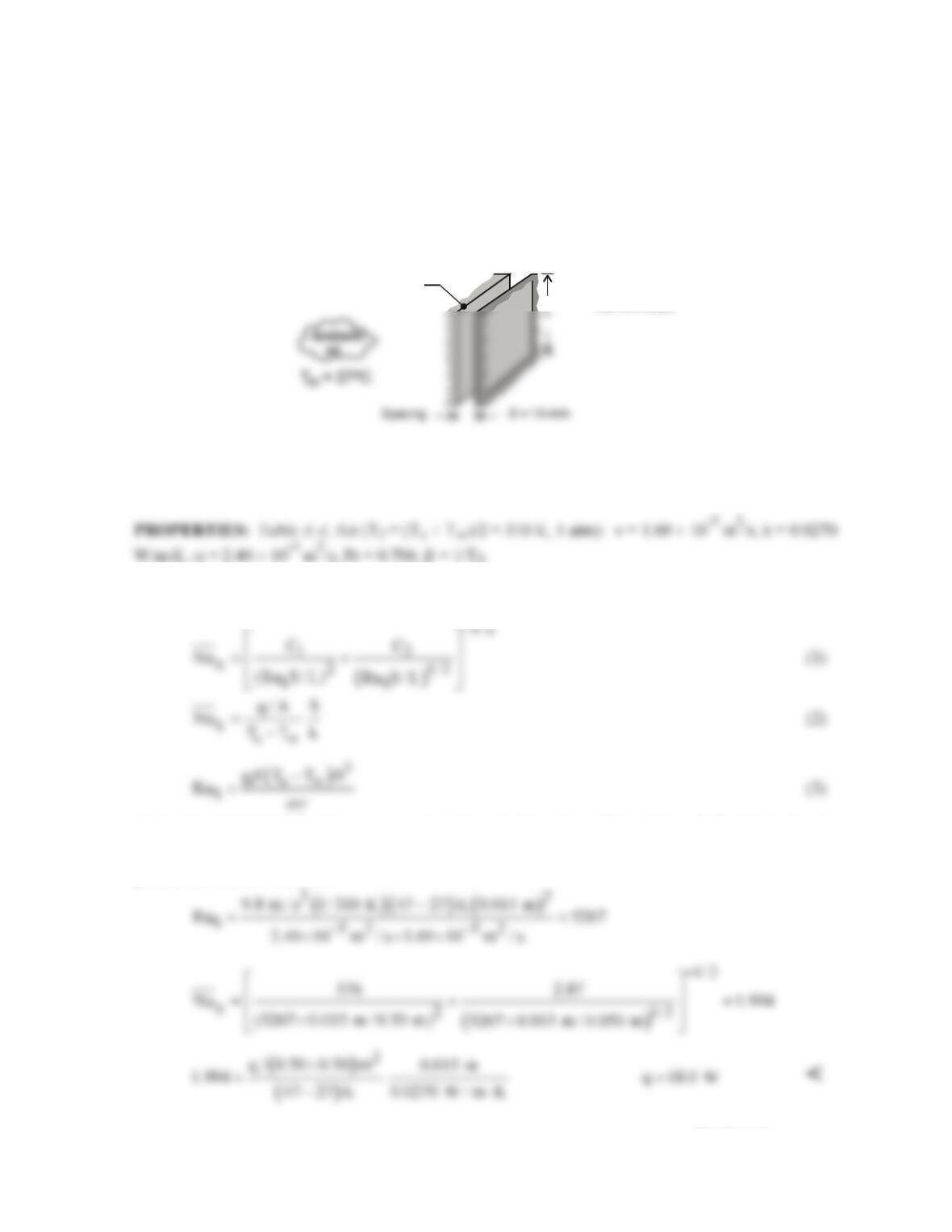
PROBLEM 9.62
KNOWN: Dimensions, spacing and temperature of plates in a vertical array. Ambient air
temperature. Total width of the array.
FIND: Optimal plate spacing for maximum heat transfer from the array and corresponding number of
plates and heat transfer.
SCHEMATIC:
W = 150 mm
ar
ASSUMPTIONS: (1) Steady-state, (2) Negligible plate thickness, (3) Constant properties.
25.5 × 10⁻⁶ m2/s, Pr = 0.704,
β
= 0.00313 K-1.
ANALYSIS: With RaS/S3L = g
β
(Ts – T∞)/
aν
L = (9.8 m/s2 × 0.00313 K-1 × 55°C)/(25.5 × 17.9 ×
10–12 m4/s2 × 0.3m) = 1.232 × 10¹⁰ m4, from Table 9.4, the spacing which maximizes heat transfer for
The corresponding heat rate is
( ) ( )
s
q N 2WL h T T ,
∞
= −
where, from Eq. 9.45 and Table 9.4,
With RaS S/L = (RaS/S3L)S4 = 1.232 × 10¹⁰ m-4 × (0.00813m)4 = 53.7,
COMMENTS: It would be difficult to fabricate heater plates of thickness
opt
S.
δ
<<
Hence, subject
to the constraint imposed on War, N would be reduced, where N ≤ 1 + War/(Sopt +
δ
).
PROBLEM 9.63
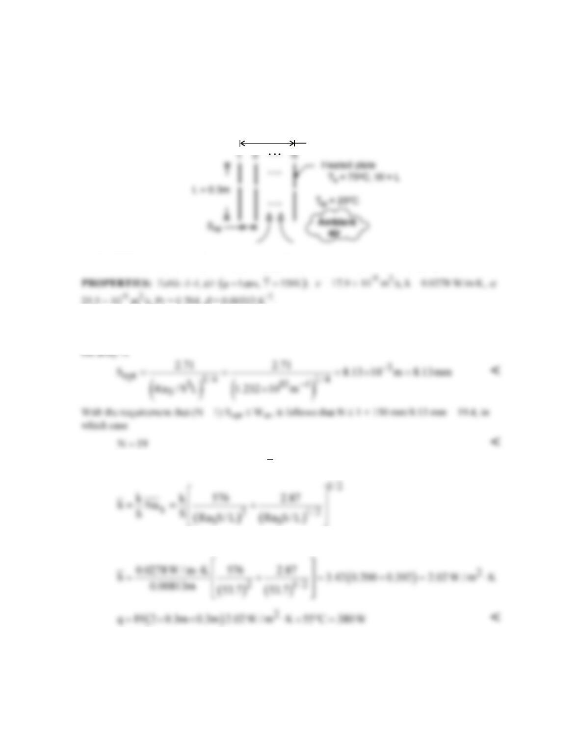
KNOWN: A bank of drying ovens is mounted on a rack in a room with an ambient temperature of
27°C; the cubical ovens are 500 mm to a side and the spacing between the ovens is 15 mm.
FIND: (a) Estimate the rate of heat loss from the facing side of an oven when its surface temperature
is 47°C, and (b) Explore the effect of the spacing dimension on the heat loss. At what spacing is the
heat loss a maximum? Describe the boundary layer behavior for this condition. Can this condition be
analyzed by treating the oven side-surface as an isolated vertical plate?
SCHEMATIC:
T = 47 C
s o
Drying oven
500 mm sides
ASSUMPTIONS: (1) Steady-state conditions, (2) Adjacent oven sides form a vertical channel with
symmetrically heated plates, (3) Room air is quiescent, and channel sides are open to the room air,
and (4) Constant properties.
ANALYSIS: (a) For the isothermal plate channel, Eq. 9.45 with Eqs. 9.37 and 9.38, allow for
calculation of the rate of heat transfer from a plate to the ambient air.
where, from Table 9.4, for the symmetrical isothermal plates, C1 = 576 and C2 = 2.87. Properties are
evaluated at the film temperature Tf. Substituting numerical values, evaluate the correlation
parameters and the heat rate.
Continued …
PROBLEM 9.63 (Cont.)
(b) Using the foregoing relations in IHT, the heat rate is calculated for a range of spacing S.
15
20
Note that the heat rate increases with increasing spacing up to about S = 20 mm. This implies that for
S > 20 mm, the side wall of the oven behaves as an isolated vertical plate. From the treatment of the
vertical channel, Section 9.7.1, the spacing to provide maximum heat rate from a plate occurs at Smax
which, from Table 9.4, is evaluated by
For the condition S = Smax, the spacing is sufficient that the boundary layers on the plates do not
overlap.
COMMENTS: Using the Churchill-Chu correlation, Eq. 9.26, for the isolated vertical plate, where
the characteristic dimension is the height L, find q = 20.2 W (RaL = 1.951 × 10⁸ and
L
h
= 4.03
W/m2⋅K). This value is slightly larger than that from the channel correlation when S > Smax, but a
good approximation.
PROBLEM 9.64
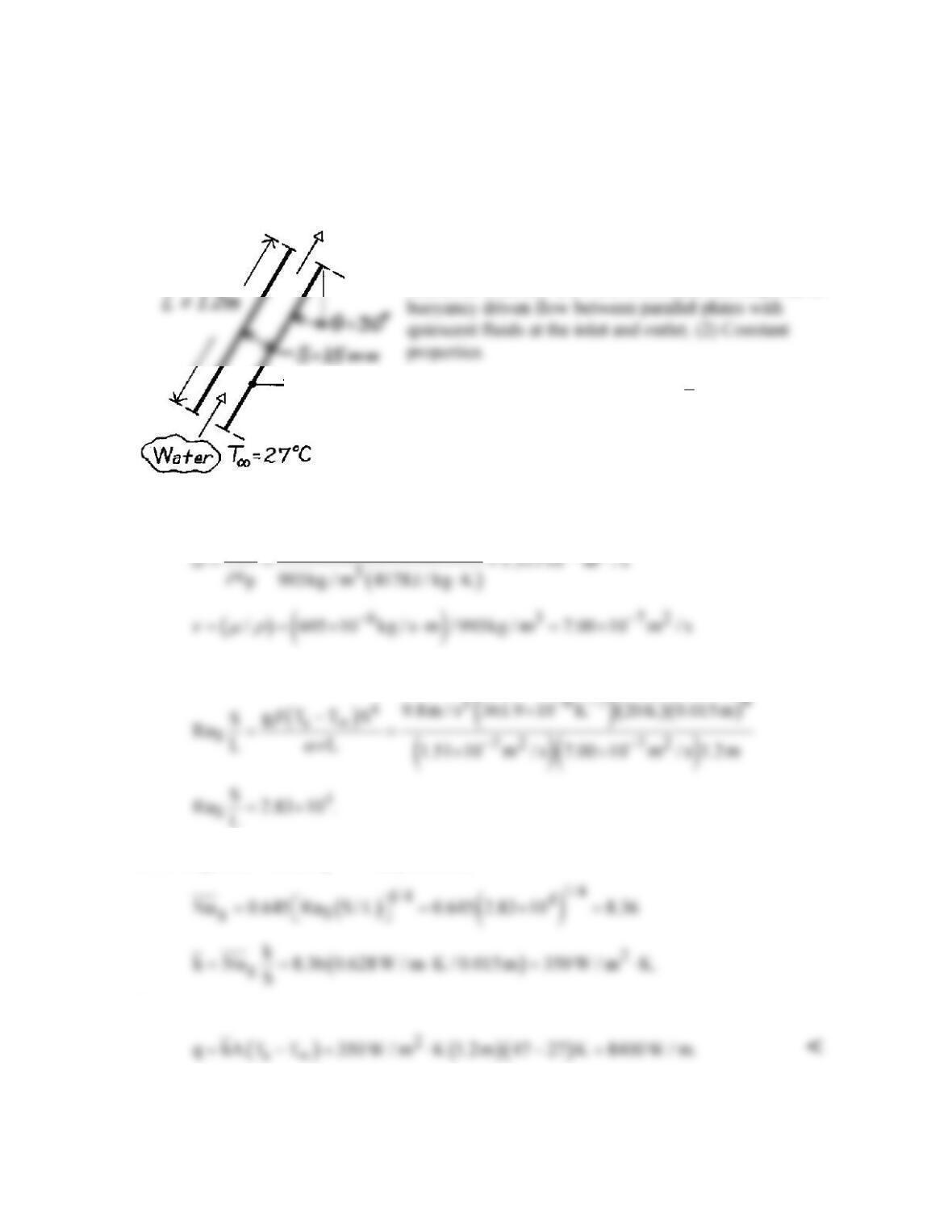
KNOWN: Inclination angle of parallel plate solar collector. Plate spacing and length.
Absorber plate and inlet temperature.
FIND: Rate of heat transfer to collector fluid.
SCHEMATIC:
ASSUMPTIONS: (1) Flow in collector corresponds to
PROPERTIES: Table A-6, Water
( )
T 310K :=
ρ = 993
kg/m3, cp = 4178 J/kg⋅K, µ = 695 × 10-6 kg/s⋅m, k =
0.628 W/m⋅K, β = 361.9 × 10⁻⁶ K–1.
ANALYSIS: With
72
k 0.628 W / m K 1.51 10 m / s
−
⋅
find
Since RaS(S/L) > 200, Eq. 9.47 may be used,
Hence the heat rate is
COMMENTS: Such a large heat rate would necessitate use of a concentrating solar collector
for which the normal solar flux would be significantly amplified.
T
s
=
47°C
PROBLEM 9.65
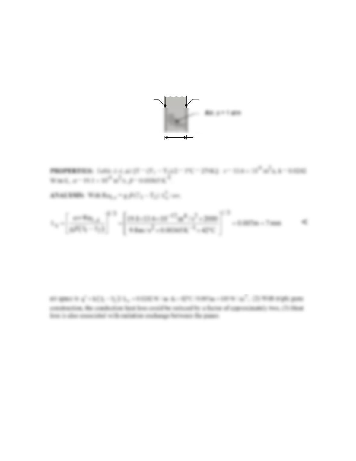
KNOWN: Critical Rayleigh number for onset of convection in vertical cavity filled with atmospheric
air. Temperatures of opposing surfaces.
FIND: Maximum allowable spacing for heat transfer by conduction across the air. Effect of surface
temperature and air pressure.
SCHEMATIC:
TC
2 o
= -20
Lc
TC
1 o
= 22
ASSUMPTIONS: (1) Critical Rayleigh number is RaL,c = 2000, (2) Constant properties.
The critical value of the spacing, and hence the corresponding thermal resistance of the air space,
increases with a decreasing temperature difference, T1 – T2, and decreasing air pressure. With
ν
=
µ
/
ρ
and
a
≡ k/
ρ
cp, both quantities increase with decreasing p, since
ρ
decreases while
µ
, k and cp are
approximately unchanged.
COMMENTS: (1) For the prescribed conditions and Lc = 7 mm, the conduction heat flux across the
PROBLEM 9.66
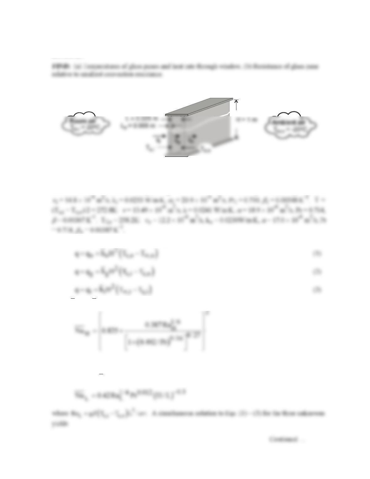
KNOWN: Temperatures and dimensions of a window-storm window combination.
FIND: Rate of heat loss by free convection.
SCHEMATIC:
ASSUMPTIONS: (1) Both glass plates are of uniform temperature with insulated
interconnecting walls and (2) Negligible radiation exchange.
ANALYSIS: For the vertical cavity,
With (H/L) = 20, Eq. 9.52 may be used as a first approximation for Pr = 0.71,
The heat loss by free convection is then
COMMENTS: In such an application, radiation losses should also be considered, and
infiltration effects could render heat loss by free convection significant.
PROBLEM 9.67
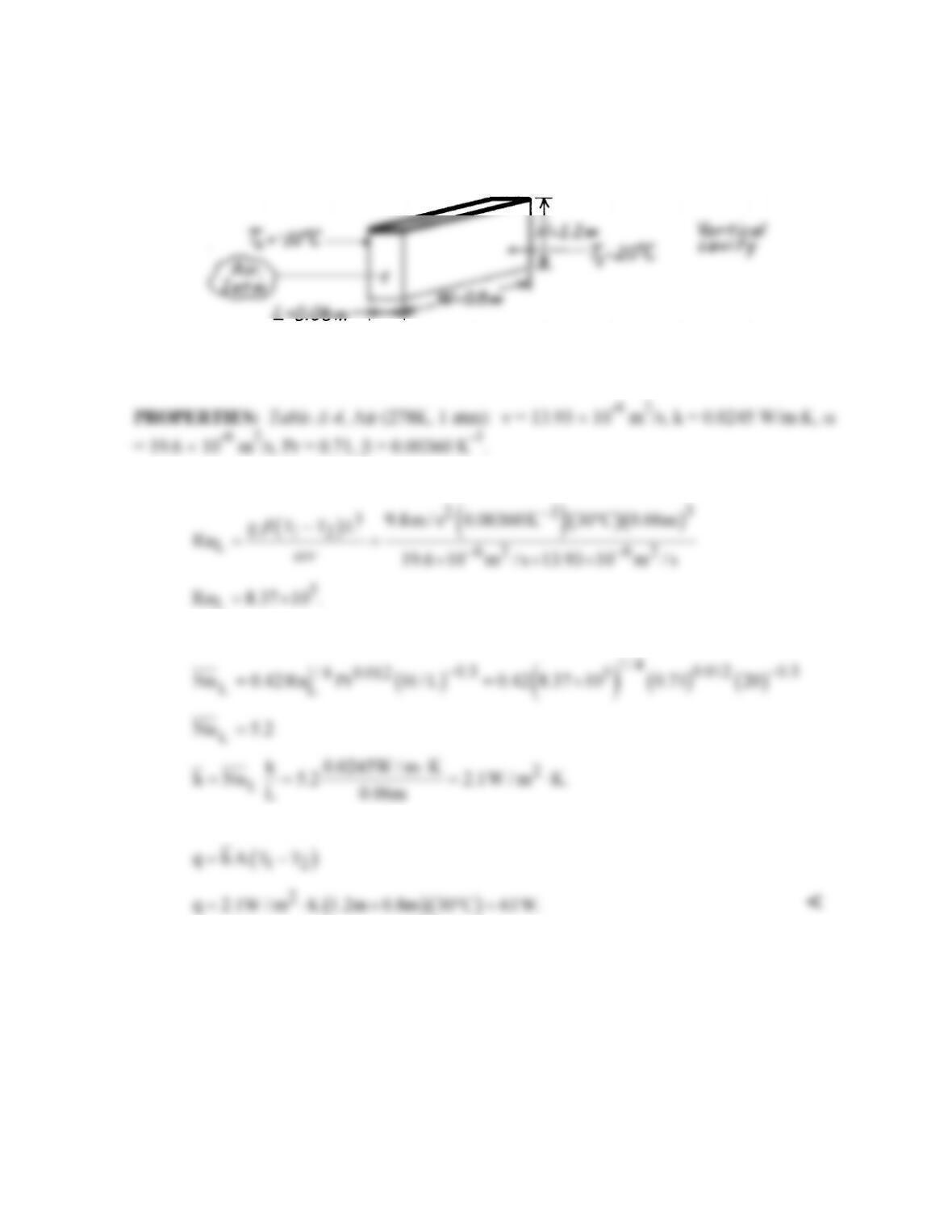
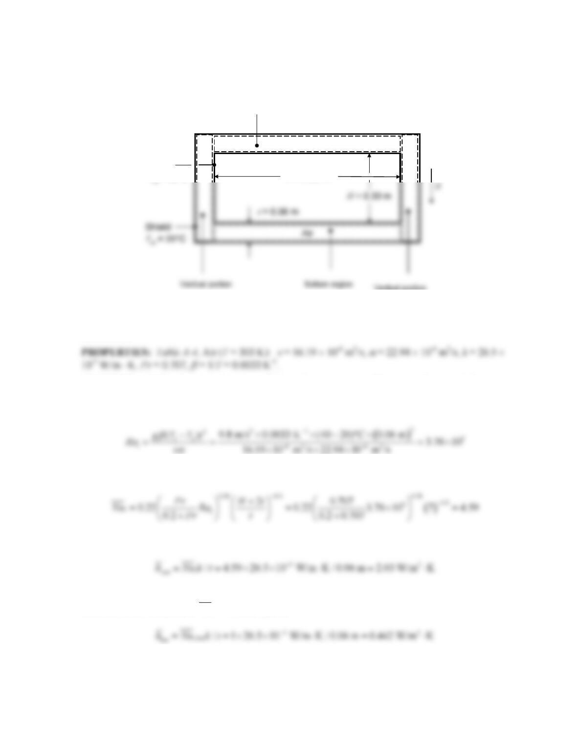
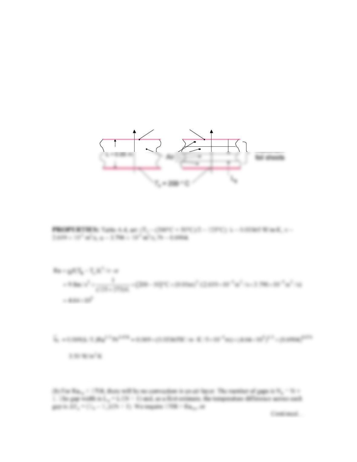
KNOWN: Dimensions of horizontal rectangular duct and radiation shield. Temperatures of duct and
shield walls.
FIND: Rate of convection heat loss per unit length.
SCHEMATIC:
ASSUMPTIONS: (1) Steady–state, (2) Uniform duct and shield wall temperatures, (3) Constant
properties, (4) Convection occurs in four distinct rectangular regions, (4) Convection is two-
dimensional.
ANALYSIS: Within the vertical portions of the enclosure, motion will occur in the vertical direction
and will likely extend from the bottom to the top of the shield wall. Thus, the aspect ratio for the
vertical regions is (H + 2t)/t = 0.42/0.06 = 7. The Rayleigh number based on the enclosure width, t, is
Therefore, Eq. 9.50 holds, and yields
and
The two horizontal regions differ from one another. The bottom region is heated from above. There is
therefore no air motion and
1
t
Nu =
, which yields
The top region is heated from below and the Rayleigh number exceeds the critical value for
convection to occur, Rat,crit = 1708. From Eq. 9.49,
Continued…
Duct
W= 0.80 m
Td= 40°C
Top region
PROBLEM 9.67 (Cont.)
Finally, the rate of convection heat loss per unit length is
COMMENTS: (1) The identified rectangular regions do not satisfy the adiabatic end condition. (2)
Presumably the shield would have a small emissivity to reduce radiation. However, if both surfaces
PROBLEM 9.68
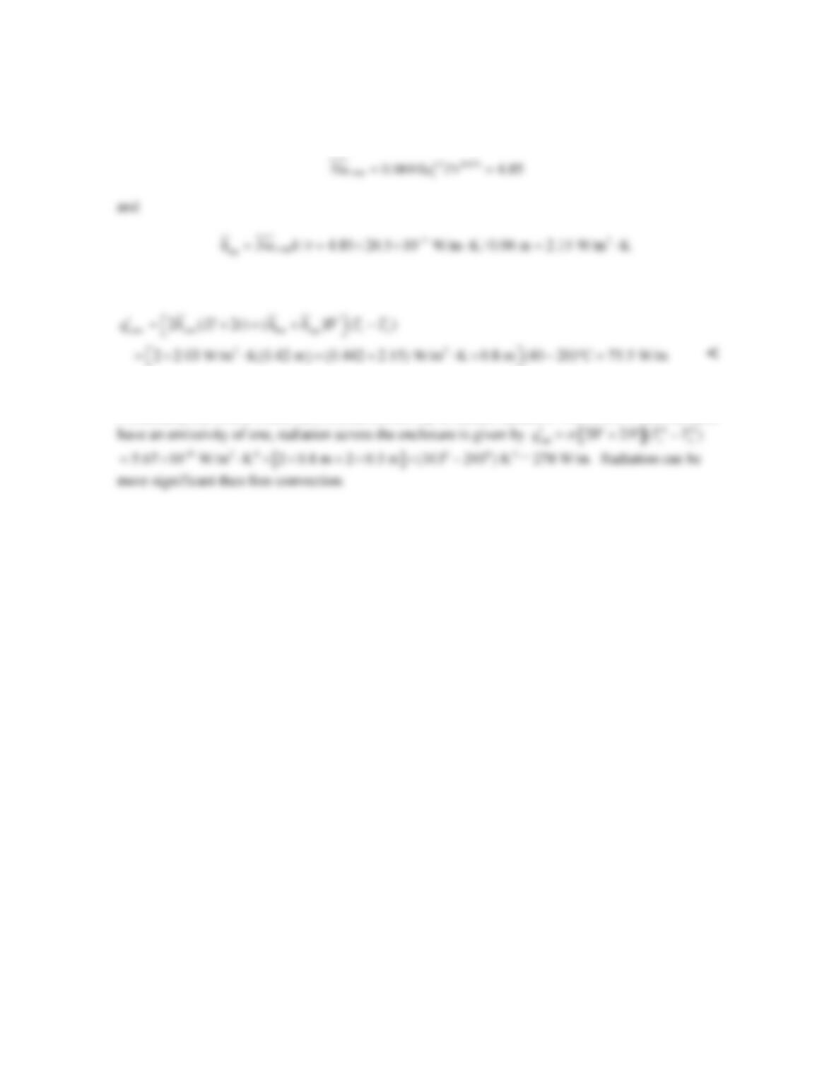
KNOWN: Absorber plate and cover plate temperatures and geometry for a flat plate solar
collector.
FIND: Heat flux due to free convection.
SCHEMATIC:
ASSUMPTIONS: (1) Aspect ratio, H/L, is greater than 12.
ANALYSIS: For the inclined enclosure,
With
70 ,
ττ
∗
<=°
Table 9.5,
Hence, the heat flux is
COMMENTS: Radiation exchange between the absorber and cover plates will also
contribute to heat loss from the collector.
PROBLEM 9.69
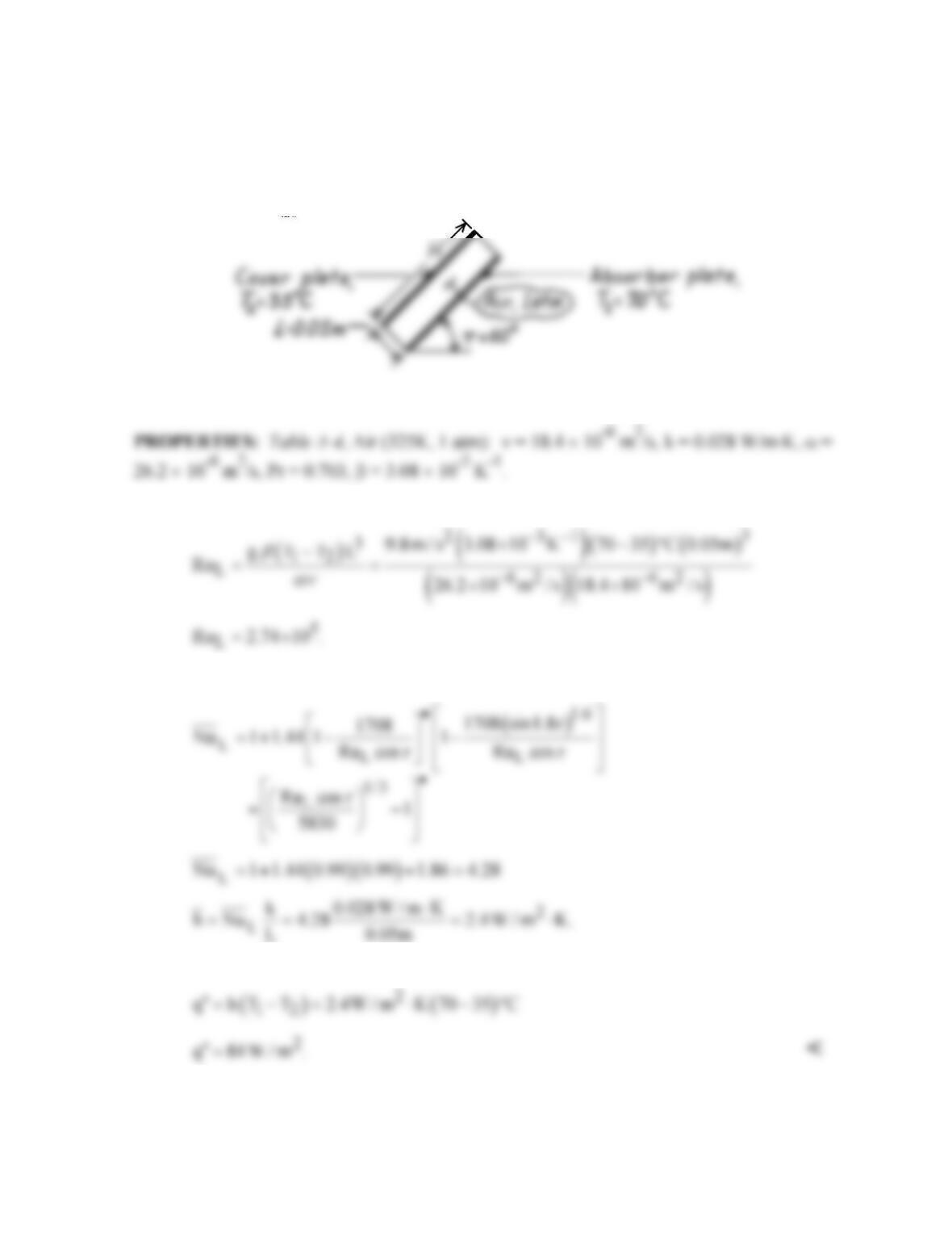
KNOWN: Dimensions and properties of paraffin slab, initial liquid layer thickness.
Temperature of the hot surface.
FIND: (a) Amount of paraffin melted over a period of 5 hours in response to bottom heating, (b)
SCHEMATIC:
ASSUMPTIONS: (1) Constant properties, (2) Neglect change of sensible energy of the liquid,
(3) One-dimensional heat transfer.
PROPERTIES: Given, see schematic.
ANALYSIS: (a) Neglecting the change in the sensible energy, the mass melted is
Using the Globe and Dropkin correlation,
Combining the equations gives
(b) The energy consumed to melt the paraffin is
Continued…
k = 0.15 W/m·K
3
Liquid
Solid
T
s
= 50°C
k = 0.15 W/m·K
3
Liquid
Solid
T
s
= 50°C
k = 0.15 W/m·K
3
Liquid
Solid
T
s
= 50°C
PROBLEM 9.69 (Cont.)
The energy associated with raising the temperature to
T (50 C 27.4 C) / 2 38.7 C= °+ ° = °
is
The ratio of the change of sensible energy to energy absorbed in the phase change is
(c) The liquid layer is heated from above. Heat transfer in the liquid phase is by conduction. The
temperature distribution in the liquid is linear if the change in sensible energy of the liquid is
neglected. Hence, an energy balance on the control surface shown in the schematic yields
Therefore,
COMMENTS: (1) For the bottom heated case at t = 5 h, the solid–liquid interface is located at
M/ρA + si = 429 kg/(770 kg/m3 × 2.5 m2) + 0.01 m = 0.233 m. The Rayleigh numbers associated
with the bottom heating case range from Ras = gβ(Ts – Tmp )si
3/νa = 9.8m/s2 × 8 × 10–4 K-1 × (50 –
the liquid phase when calculating the melting rate or solid–liquid interface location.
PROBLEM 9.70
KNOWN: Dimensions of horizontal air space separating plates of known temperature.
FIND: (a) Convective heat flux for a 50 mm gap, hot and cold plate temperatures of Th = 200°C
and Tc = 50°C, respectively, (b) Minimum number of thin aluminum sheets needed to suppress
convection, (c) Conduction heat flux with the sheets in place.
SCHEMATIC:
ASSUMPTIONS: (1) Constant properties, (2) Steady-state conditions, (3) Foil sheets have
negligible conduction resistance and negligible thickness.
ANALYSIS: (a) The Rayleigh number is
Using the Globe and Dropkin correlation,
Therefore,
“2 2
conv
q 3.50W / m K (200 50) C 525W / m= ⋅ × − °=
<
qcond
qconv
Tc= 50 °C
” “
qcond
qconv
Tc= 50 °C
” “
PROBLEM 9.70 (Cont.)
from which we may determine N > 3.06. Therefore, we specify N = 4. <
(c) Neglecting the thickness and thermal resistance of the foil sheets,
COMMENTS: (1) Installation of the foils results in a 100 – 101/525 = 81 % reduction in heat
transfer across the large gap. (2) Because of the temperature dependence of the thermophysical
properties, we should check to make sure the Rayleigh numbers associated with the top and
bottom gaps do not exceed 1708. Assuming ∆Tg = (Th – Tc)/(N + 1) = 150°C/(5) = 30°C and
PROBLEM 9.71
KNOWN: Dimensions of double pane window. Thickness of air gap. Temperatures of room and
ambient air.
SCHEMATIC:
ASSUMPTIONS: (1) Steady-state, (2) Negligible glass pane thermal resistance, (3) Constant
properties.
PROPERTIES: Table A-3, Plate glass: kp = 1.4 W/m⋅K. Table A-4, Air (p = 1 atm). Tf,i = 287.6K:
ANALYSIS: (a) The heat rate may be expressed as
where
o
h
and
i
h
may be obtained from Eq. (9.26),
with
( )
3
H o s,o ,o o o
Ra g T T H /
β aν
∞
= −
and
( )
3
H i ,i s,i i i
Ra g T T H / ,
β aν
∞
= −
respectively. Assuming
47
Lg
10 Ra 10 , h<<
is obtained from