word_size = 16,
word_size_out = 2*word_size + 2,
write_ptr_size = 4,
b0 = 8’d7, // Filter coefficients
);
reg [word_size -1: 0] Sample_Array [0: FIR_order -1];
reg [write_ptr_size -1: 0] write_ptr;
parameter max_write_ptr = 4’d7;
integer k;
always @ (posedge clock)
if (reset == 1) begin
for (k = 1; k <= FIR_order; k = k+1) Sample_Array[k] <= 0;
end
else case (write_ptr)
0: Data_out <= b0*Data_in + b8*Sample_Array[0] + b7*Sample_Array [1]
3: Data_out <= b0*Data_in + b8*Sample_Array[3] + b7*Sample_Array [4]
+ b6*Sample_Array [5] + b5*Sample_Array [6] + b4*Sample_Array [7]
+ b3*Sample_Array [0] + b2*Sample_Array [1] + b1*Sample_Array [2];
4: Data_out <= b0*Data_in + b8*Sample_Array[4] + b7*Sample_Array [5]
+ b6*Sample_Array [6] + b5*Sample_Array [7] + b4*Sample_Array [0]
+ b3*Sample_Array [1] + b2*Sample_Array [2] + b1*Sample_Array [3];
+ b3*Sample_Array [4] + b2*Sample_Array [5] + b1*Sample_Array [6];
default: Data_out <= 0;
endcase
module t_FIR_Filters ();
parameter word_size = 16, word_size_out = 2*word_size + 2;
wire [word_size_out -1: 0] Data_out_SReg, Data_out_CBuf;
reg [word_size -1: 0] Data_in;
reg clock, reset;
initial fork
reset = 0;
#10 reset = 1;
#20 reset = 0;
Data_in = 0;
T1 0 T2 0 Tdelta 0
Name 020 40 60 80
Default
clock
reset
Data_in[15:0]
Data_out_SRe
g
[33:0]
\Sample_Array[1] [15:0]
\Sample_Array[2] [15:0]
xxxx
X
0000
0000
0
0001
0000
7
0001
0001
17
32
46
52
46
32
0000
0000
0000

Problem 9-18
The pipeline in Figure P9-18 does not maintain data coherency. To establish coherency,
Advanced Digital Design with the Verilog HDL, Second Edition
Michael D. Ciletti
Prentice Hall, Pearson Education, 2011
Problem 9-19
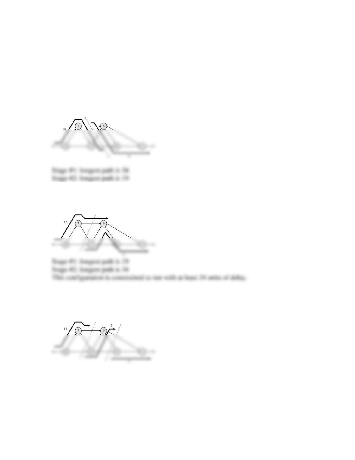
The longest path through the graph has a delay of 53. For the given graph, the optimal
(best balance) placement of a single stage of pipeline registers for coherent datapaths is at
the boundary between the cutsets shown below:
An alternative:
Note: If two stages of pipliene registers are used, the configuration shown below can run
with a delay of 21 units, less than at one-half of the delay of the machine without a
pipeline.

Problem 9-20
For an example, see the solution to Problem 9-3.
Problem 9-22
A slight modification of the Verilog module presented in the solution to Problem 9-3 is
given below.
always @ (posedge clock)
if (reset) begin
// for (j = 0; j <= N -1; j = j + 1) xc[j] <= 0;
xc[0] = 0;
xc[1] = 0;
xc[2] = 0;
xc[3] = 0;
endmodule
module t_Convolution_Baseline #(parameter N = 4, size_y = 6, size_x = 4)();
wire [size_y -1: 0] y;
reg [size_x -1: 0] x_in;
reg clock, reset;
Convolution_Baseline M0 (y, x_in,clock, reset);
initial #500 $finish;

#90 reset = 0;
#110 x_in = 1; // Test for impulse response
Problem 9-24
module decimator_3_unit # (parameter word_length = 8, latency = 4)(
output [word_length*latency -1: 0] data_out,
input [word_length-1: 0] data_in,
input Go,
input clock, reset
);
wire load, hold;
);
reg [(word_length*latency) -1: 0] Shft_Reg; // Shift reg
reg [(word_length*latency) -1: 0] Int_Reg; // Intermediate reg
reg [(word_length*latency) -1: 0] Decim_Reg; // Decimation reg
always @ (posedge clock) // Decimation
if (reset) begin
always @ (posedge clock) // Byte buffering
if (reset) Decim_Reg <= 0;
else if (!hold) Decim_Reg <= Int_Reg;
assign data_out = Decim_Reg;
endmodule
always @ (posedge clock, posedge reset)
if (reset) N <= 2’b00; else if (clr_N) N <= 2’b00; else if (incr_N) N <= N + 1;
always @ (posedge clock, posedge reset)
if (reset) state <= S_idle; else state <= next_state;
end
S_wait1: begin hold = 0; next_state = S_wait2; end
S_wait2: begin clr_N = 1; hold = 0;
if (Go) next_state = S_shifting;
else next_state = S_idle;
end
endcase
end
endmodule
initial fork
reset = 1;
#20 reset = 0;
#40 data_in = 8’hab;
#160 data_in = 8’hcd;
#280 data_in = 8’hef;
#50 Go = 1;
//#160 Go = 0;
join
endmodule