Chap. 9 Spread Footings-Geotechnical Design
9.1 Which method of expressing footing width criteria (allowable bearing pressure or design chart)
would be most appropriate for each of the following structures?
a) A ten-story reinforced concrete building
b) A one-story wood frame house
c) A nuclear power plant
d) A highway bridge
Solution
a) A ten–story reinforced concrete building: This structure is likely to have a significant
variety of column loads and the design loads are likely to change during the design

Chap. 9 Spread Footings-Geotechnical Design
9.2 Explain why an 8-ft wide footing with q= 3,000 lb/ft2 will settle more than a 3–ft wide one
with the same q.
Solution
Larger footings produce large pressure bulbs than smaller footings. Therefore, large footings

Chap. 9 Spread Footings-Geotechnical Design
9.3 Under what circumstances would bearing capacity most likely control the design of spread
footings? Under what circumstances would settlement usually control?
Solution
Bearing capacity will generally control design only for short-term conditions on soft cohesive
Chap. 9 Spread Footings-Geotechnical Design
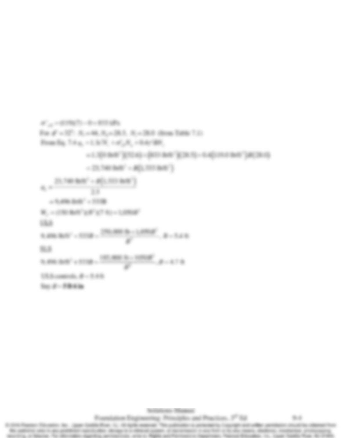
9.4 A proposed building column will carry a downward maximum unfactored load combination of
250 k and a service load of 185 k. This column is to be supported on a square footing at a
depth of 7 ft in a silty sand with the following engineering properties: γ = 119 lb/ft3 above the
groundwater table and 122 lb/ft3 below, c’ = 0,
φ
’ = 32o, N60 = 30. The groundwater table is
15 ft below the ground surface. The allowable settlement, δa, is 0.75 in. The ASD, factor of
safety against a bearing capacity failure is 2.5. Determine the design footing width clearly
identifying whether it is controlled by settlement or bearing capacity.
Solution
Chap. 9 Spread Footings-Geotechnical Design
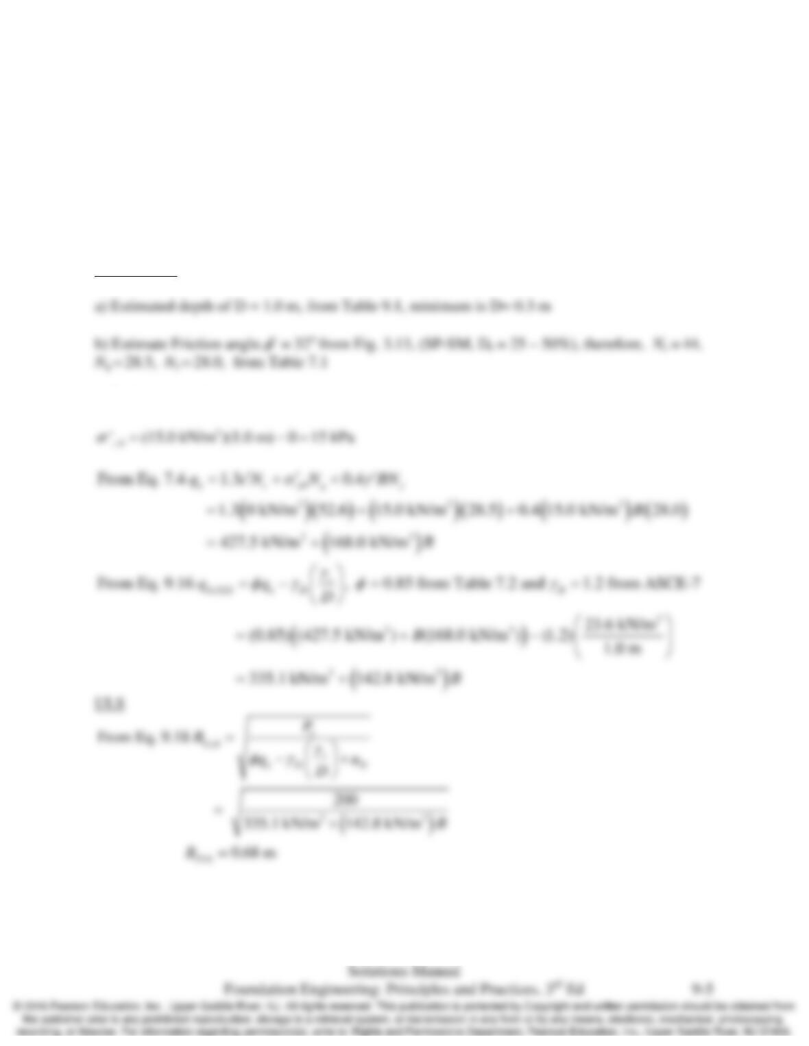
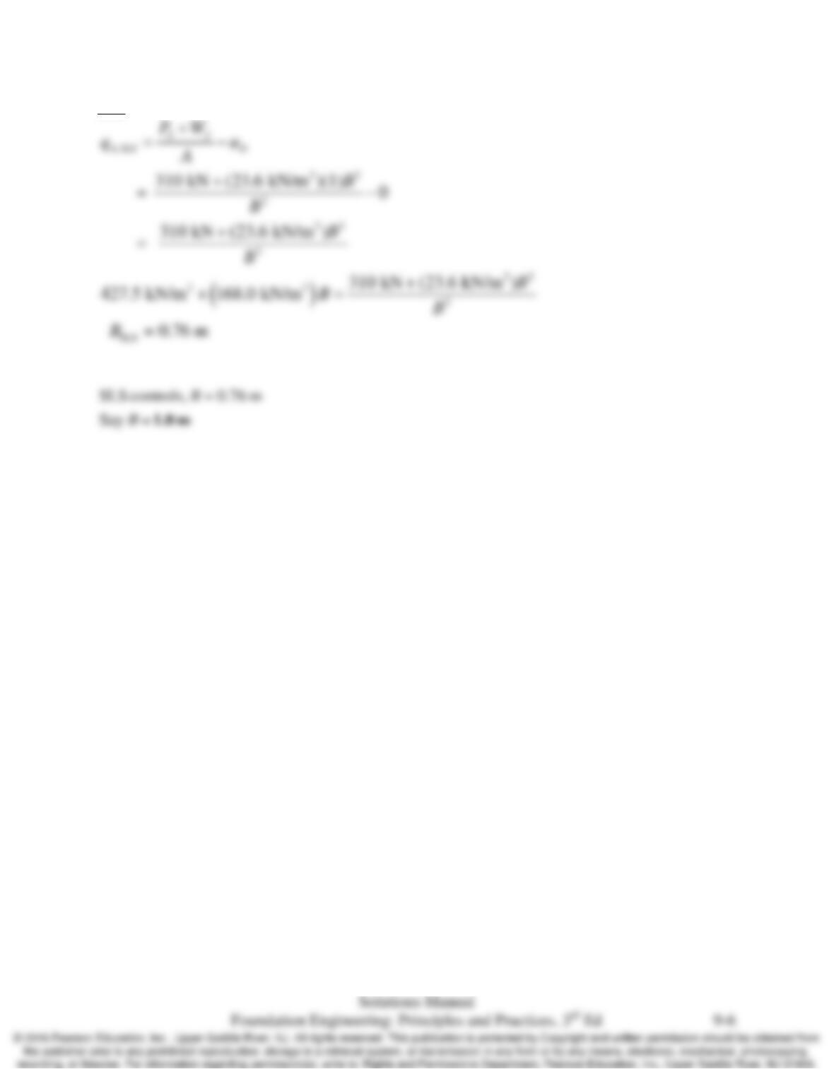
9.5 A building column carries a downward factored ultimate load of 310 kN and a service load of
200 kN. It is underlain by a lightly overconsolidated clay (OCR = 2) with the following
engineering properties: Cc = 0.20, Cr = 0.05, e = 0.7, and γ = 15.0 kN/m3 above the
groundwater table and 16.0 kN/m3 below. The groundwater table is at a depth of 1.0 m below
the ground surface. Using LRFD, determine the design footing width clearly identifying
whether it is controlled by settlement or bearing capacity.
Solution
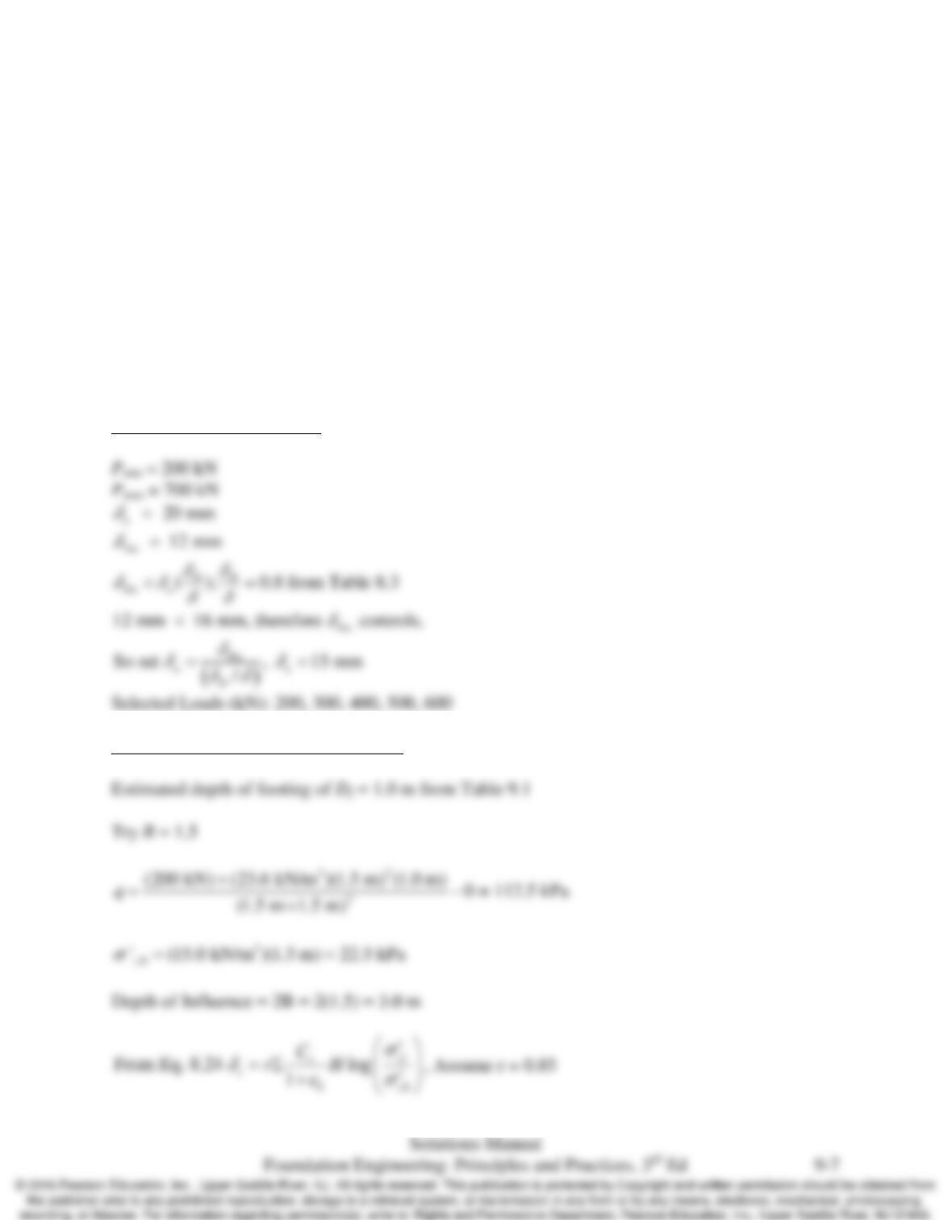
Assumptions
c) Cohesion, c’=0
Chap. 9 Spread Footings-Geotechnical Design
SLS
Chap. 9 Spread Footings-Geotechnical Design
9.6 A proposed office building will have unfactored column design loads between 200 and 1000
kN and service loads between 150 and 700 kN. These columns are to be supported on spread
footings which will be founded in a silty clay with the following engineering properties: γ =
15.1 kN/m3 above the groundwater table and 16.5 kN/m3 below, su = 200 kPa,
Cr/(1+e0) = 0.020, σm = 400 kPa. The groundwater table is 5 m below the ground surface.
The required factor of safety against a bearing capacity failure must be at least 3 and the
allowable total settlement, δa, is 20 mm and the allowable differential settlement, δDa, is 12
mm.
Prepare both serviceability and bearing capacity design charts, using ASD for ULS analysis.
Then, comment on the feasibility of using spread footings at this site.
Solution
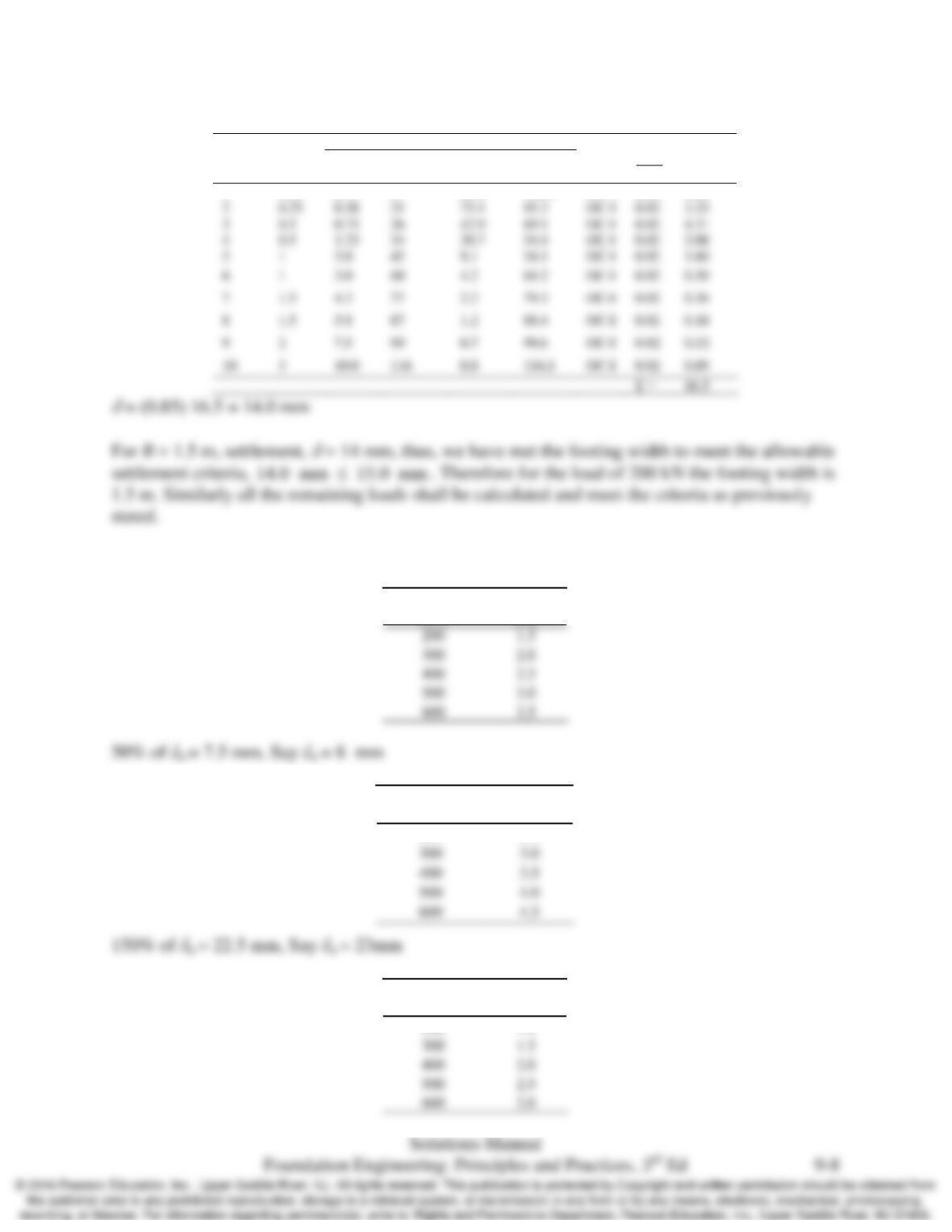
Serviceability design Charts
Calculation example for load = 200 kN
Chap. 9 Spread Footings-Geotechnical Design
Layer
No.
H
(m)
At midpoint of layer
Case
0
1
r
C
e+
δc
(mm)
zf (m)
σ’
z0
(kPa)
Δσ
z
(kPa)
σ’
zf
(kPa)
1
0.25
0.13
17
89.4
106.2
OC-I
0.02
4.00
Shown below is the design table for the serviceability loads and footing widths.
200
500
600
Loads
(kN)
B
(m)
Loads
(kN)
B
(m)
200
2.5
Loads
(kN)
B
(m)
200
1.0
3
0.75
26
42.9
69.1
OC-I
0.02
4.21
4
1.25
34
20.7
54.4
OC-I
0.02
2.08
5
1
45
54.1
OC-I
0.02
1.60
Chap. 9 Spread Footings-Geotechnical Design
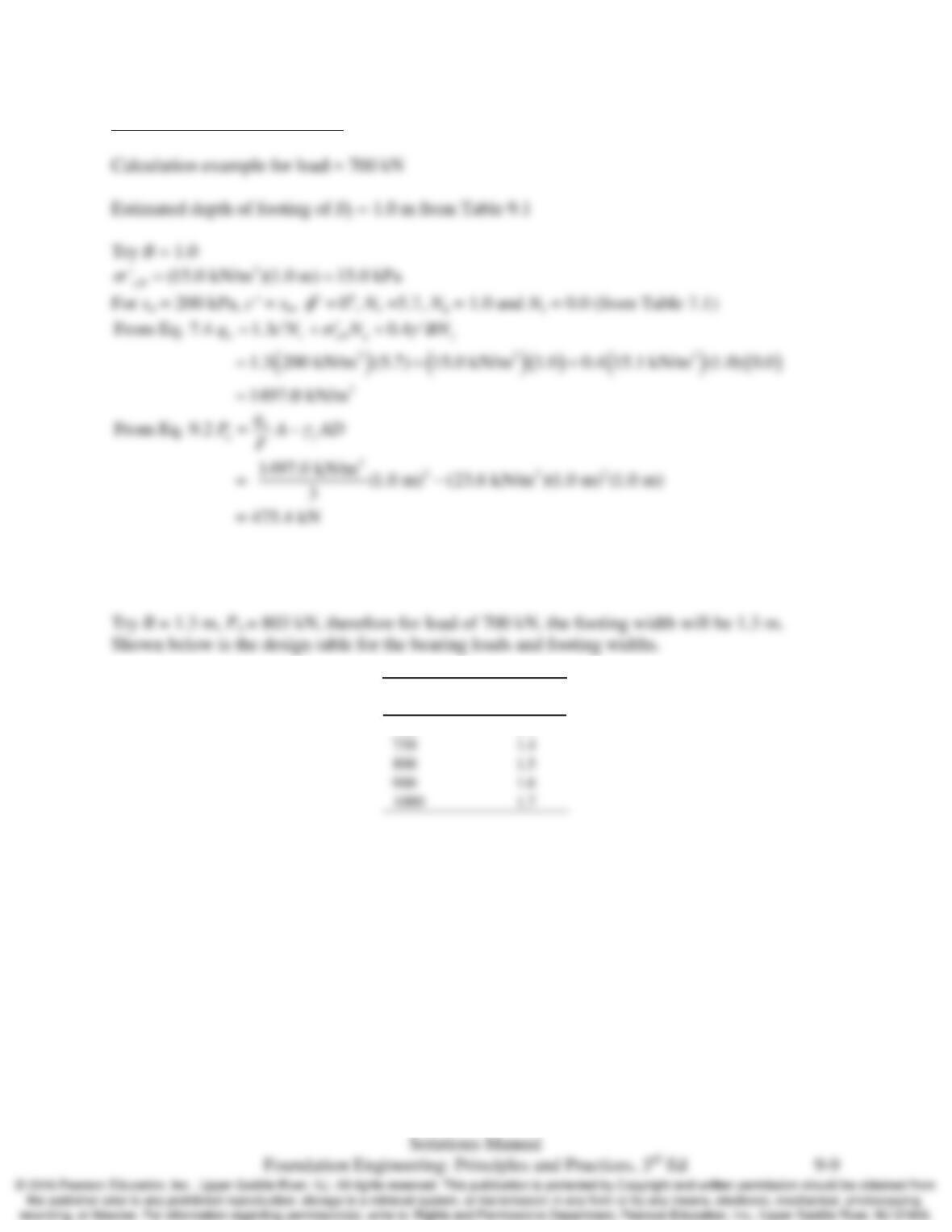
Bearing capacity design Charts
For Pa = 475 kN,, the load of 700 kN does not meet the requirement P < Pa. Therefore try
another width to meet the criteria.
Loads
(kN)
B
(m)
700
1.3
750
1.4
800
1.5
900
1.6
1000
1.7
Chap. 9 Spread Footings-Geotechnical Design
9.7 Repeat Problem 9.6 using LRFD for the ULS analysis and assuming the factored ultimate
loads range from 250 to 1350 kN. Service loads range remains as stated in Problem 9.6
Solution
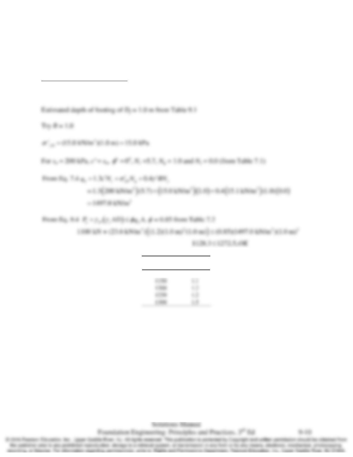
Bearing capacity design Charts
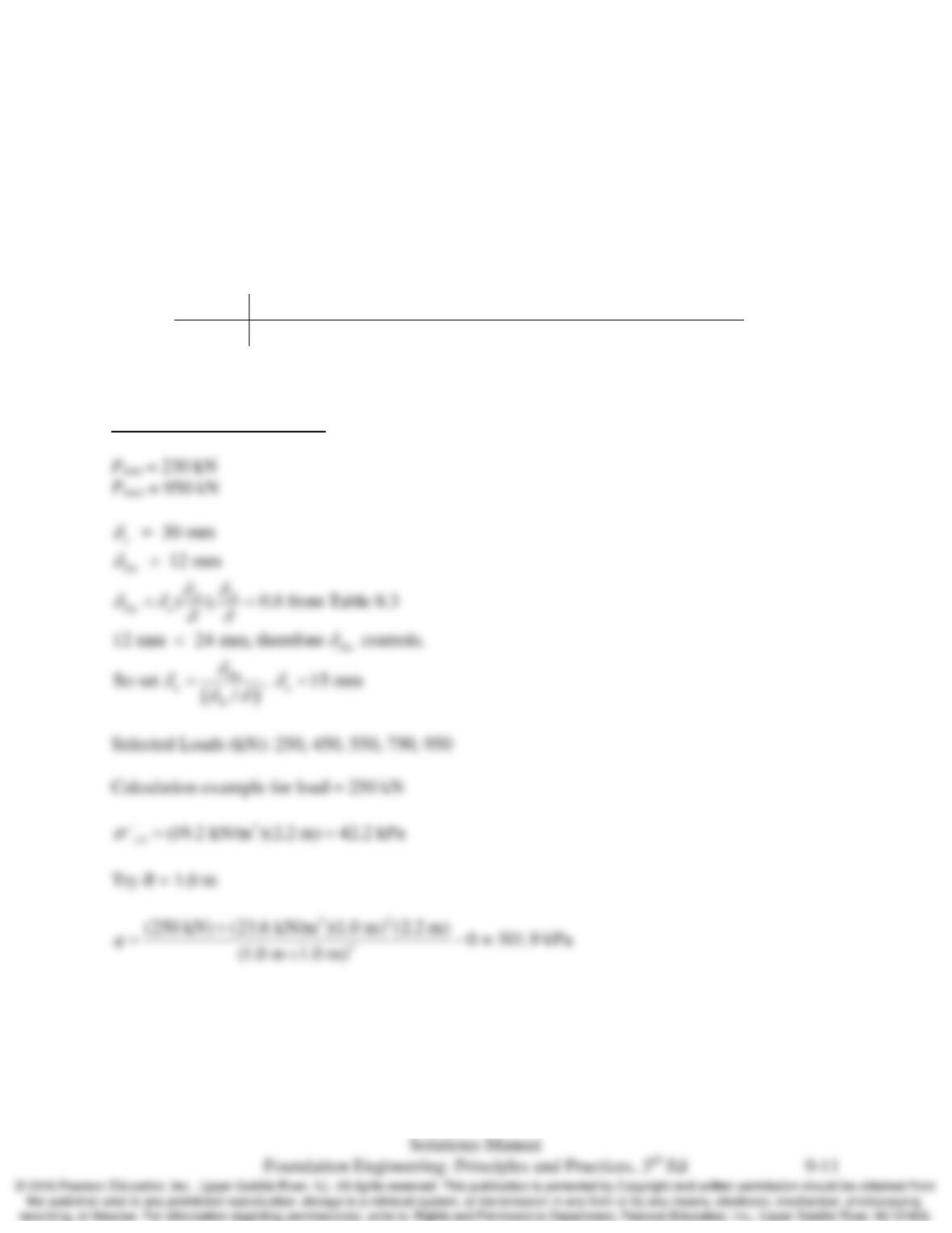
Calculation example for load = 1100 kN
1.1
1.2
Loads
(kN)
B
(m)
1100
1.0
Chap. 9 Spread Footings-Geotechnical Design
9.8 A proposed industrial building will carry unfactored column loads ranging from 280 to 1200
kN and service loads from 230 to 950 kN. The allowable settlements are δa, = 30 mm and
δDa = 12 mm. It is supported on a cohesionless sand with,
φ
’ = 35o and γ = 19.2 kN/m3.
Footings at this site will be at a depth of 2.2 m and the ground water table is at 5m. A
dilatometer test run at the site has returned the following modulus profile.
Prepare both serviceability and bearing capacity design charts, using ASD for ULS analysis.
Then, comment on the feasibility of using spread footings at this site.
Depth (m) 2 3 4 5 6 7 8 9 10 11 12 13
M (MPa) 18.3 20.6 19.0 21.1 35.2 40.0 37.3 30.1 31.9 40.0 40.8 42.0
Solution
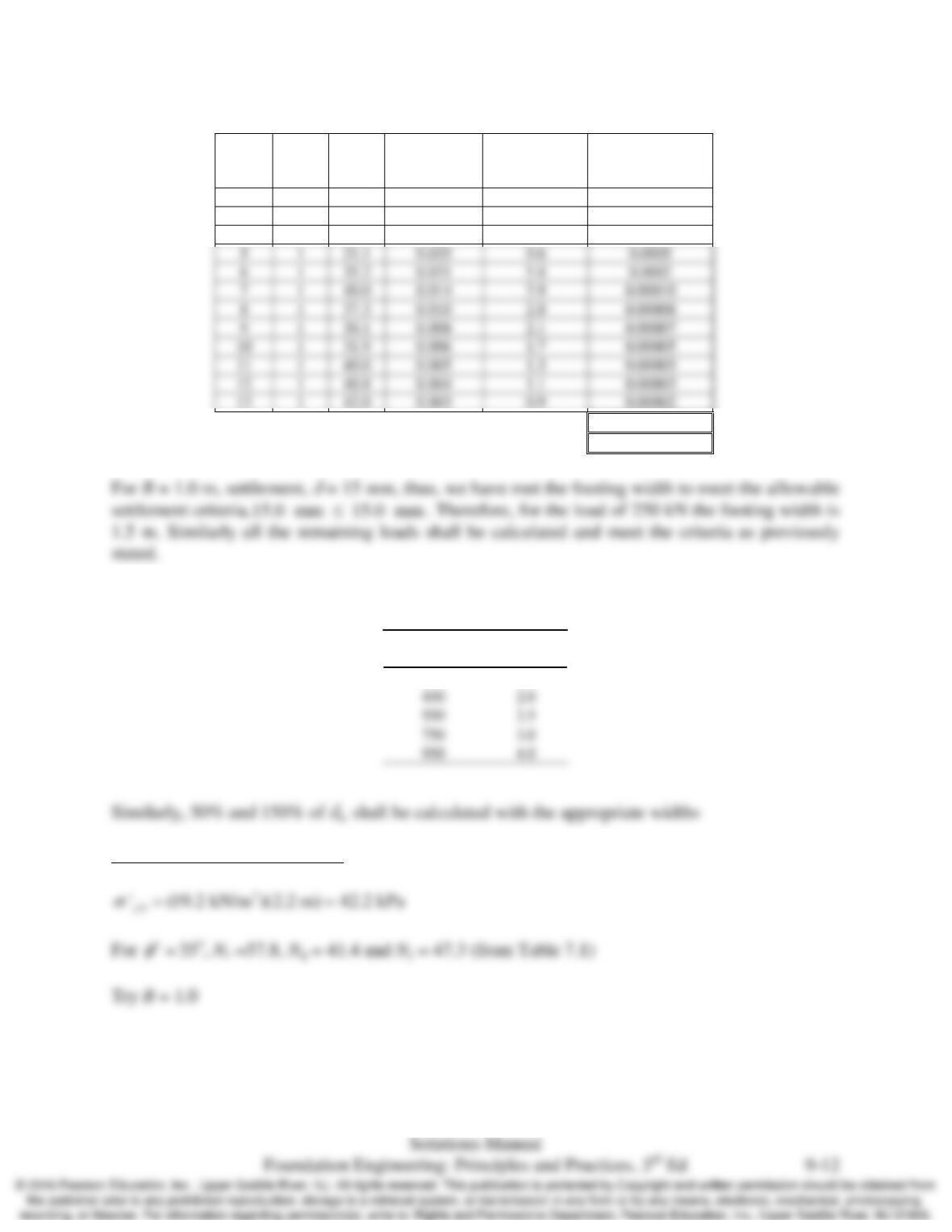
Serviceability Design Charts
Chap. 9 Spread Footings-Geotechnical Design
Depth
(m)
H
(m)
M
(MPa)
I
q
From Eq.
3.14
Δσ
z
= q
ʹ
× I
q
(kPa)
δ = (Δσ
z
×H)/M
(m)
2
1
18.3
0.705
192.8
0.0105
3
1
20.6
0.169
46.3
0.0022
4
1
19.0
0.067
18.2
0.0010
Σ
0.0147 m
15 mm
Shown below is the design table for the serviceability loads and footing widths.
450
2.0
550
2.5
750
3.0
950
4.0
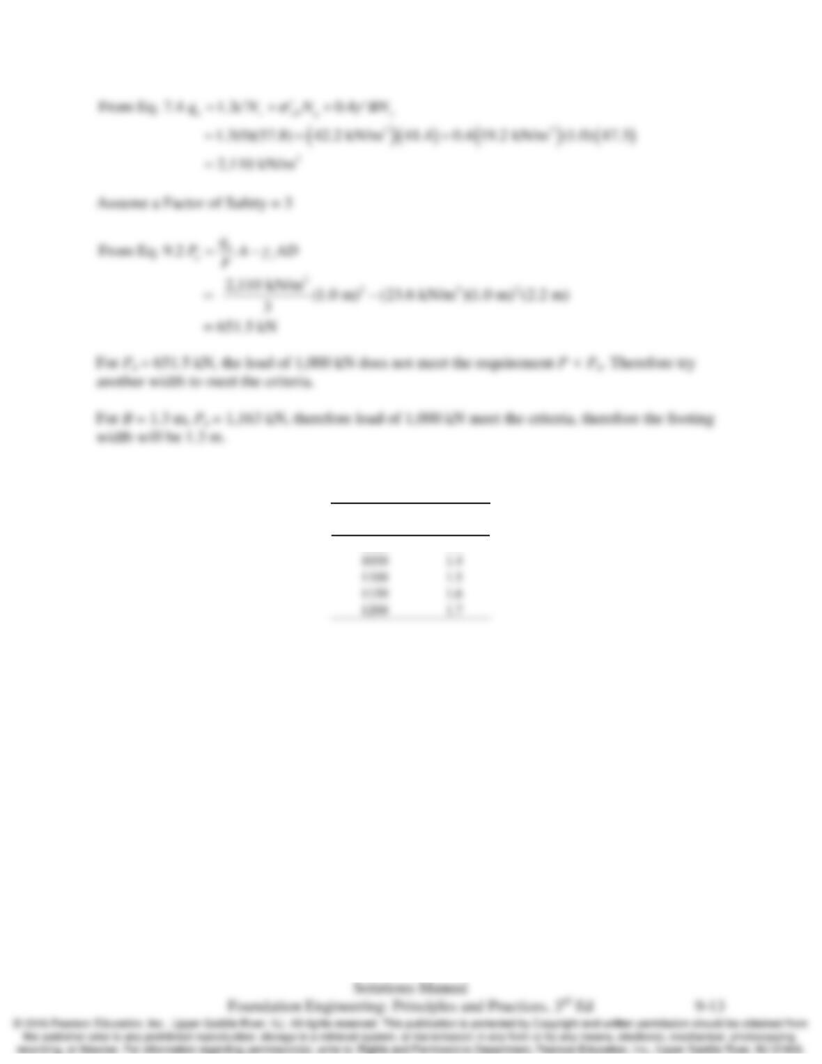
Bearing capacity design Charts
Loads
(kN)
B
(m)
250
1.0
5
1
21.1
0.035
0.0005
6
1
35.2
0.021
0.0002
7
1
40.0
0.014
8
1
37.3
0.010
9
1
30.1
0.008
1
31.9
0.006
1
40.0
0.005
1
40.8
0.004
1
42.0
0.003
Chap. 9 Spread Footings-Geotechnical Design
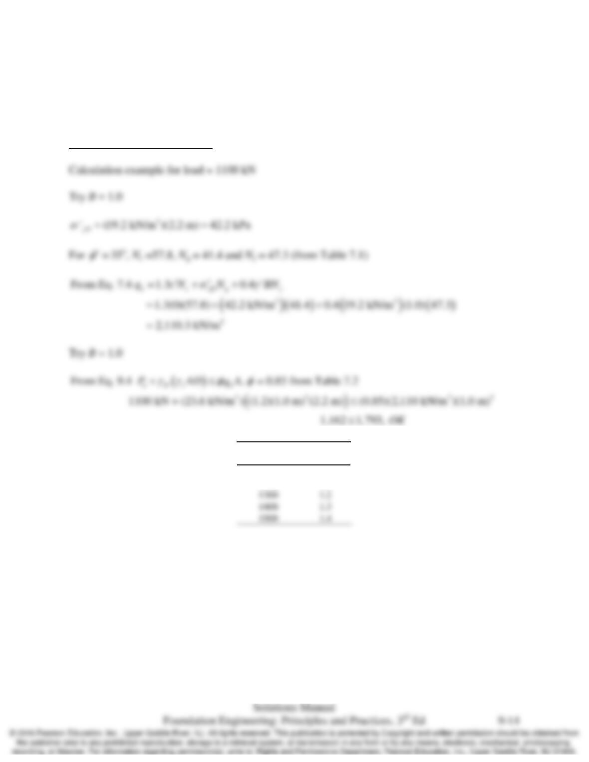
Shown below is the design table for the bearing loads and footing widths.
1050
1.4
Loads
(kN)
B
(m)
1000
1.3
Chap. 9 Spread Footings-Geotechnical Design
9.9 Repeat Problem 9.8 using LRFD for the ULS analysis and assuming the factored ultimate loads
range from 300 to 1500 kN. Service loads range remains as stated in Problem 9.8.
Solution
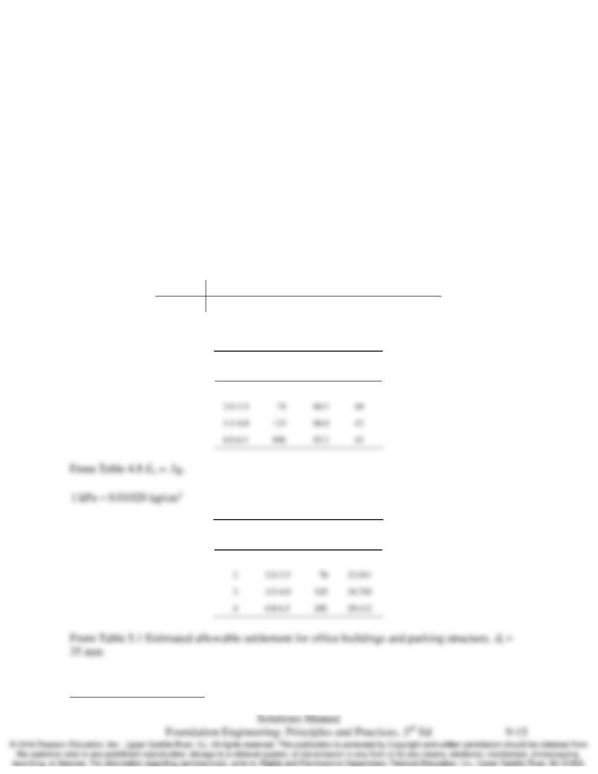
Bearing capacity design Charts
1.2
1.3
1.4
Loads
(kN)
B
(m)
1100
1.0
1200
1.1
Chap. 9 Spread Footings-Geotechnical Design
9.10 Several cone penetration tests have been conducted at a site underlain by a young, normally
consolidated silica sand deposit. Based on these tests, an engineer has developed the following
design soil profile.
This soil has an average unit weight of 18.1 kN/m3 above the groundwater table and 20.8 kN/m3
below. The groundwater table is at a depth of 3.1 m. An office building with a parking structure
is to be built at this site with ASD column loads of 400 to 1500 kN and service loads of 380 to
1100 kN. Square footings are to be used at a depth of 1 m. Using these data, create design
charts for both serviceability and ultimate limit states using ASD with a factor of safety of 2.5
and a design life of 50 years.
Hint: In a homogeneous soil, the critical shear surface for a bearing capacity failure extends to a
depth of approximately B below the bottom of the footing. See Chapter 4 for a correlation
between qc in this zone and
φ
′.
Depth (m) 0 – 2.0 2.0 – 3.5 3.5 – 4.0 4.0 – 6.5
qc (kg/cm2) 40 78 125 100
Solution
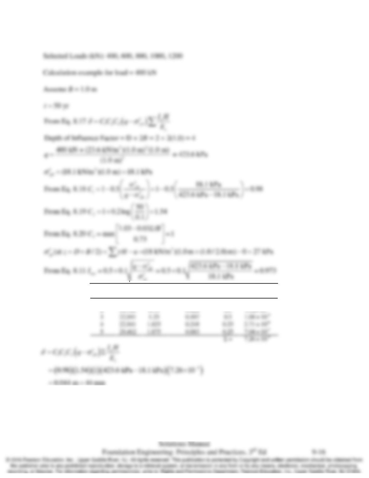
Estimated friction angles taken from Figure 4.31
Depth
(m)
qc
(kg/cm2)
σ’z
(kPa)
φo
0.0–2.0 40 36.2 35
Layer Depth
(m)
qc
(kg/cm2)
Es
(kPa)
1 0.0–2.0 40 11,765
Serviceability Design Charts
Chap. 9 Spread Footings-Geotechnical Design
Layer
No.
E
s
(kPa)
z
f
(m)
I
ε
Eqs. 8.12 & 8.13
H
(m)
δ
Iε H/Es
1
11,765
0.25
0.547
0.5
2.32 ×10⁻⁵
2
11,765
0.75
0.828
0.5
3
22,941
1.25
0.497
0.5
1.08 ×10⁻⁵
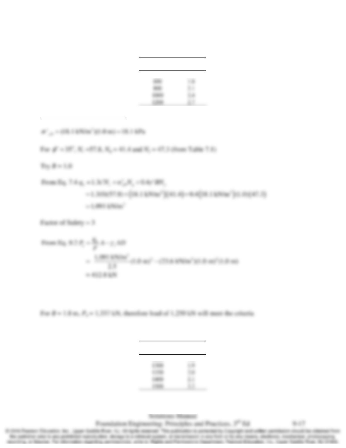
To meet serviceability requirements,
a
δδ
≤
; With B = 1.0 m,
δ
= 44 mm, therefore iterative
solutions of B should be calculated to meet the allowable settlement.
Shown below is the design table for the serviceability loads and footing widths.
Chap. 9 Spread Footings-Geotechnical Design
Bearing capacity design Charts
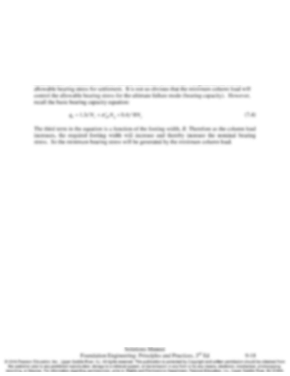
For Pa = 412.8 kN, the load of 1,250 kN does not meet the requirement P < Pa. Therefore, try
another width to meet the criteria.
Shown below is the design table for the bearing loads and footing widths.
1300
1.9
1350
2.0
1400
2.1
1500
2.2
Loads
(kN)
B
(m)
400
1.5
Loads
(kN)
B
(m)
1250
1.8
600
1.8
1200
2.7
Chap. 9 Spread Footings-Geotechnical Design
9.11 A proposed building will have column loads ranging from 40 to 300 k. All of these columns will
be supported on square spread footings. When computing the allowable bearing pressure, qA,
which load should be used to perform the bearing capacity analyses? Which should be used to
perform the settlement analyses? Explain.
Solution
Settlement analysis uses the maximum service loads and bearing capacity uses the minimum
column loads. It should be obvious that the maximum service load will generate the lowest
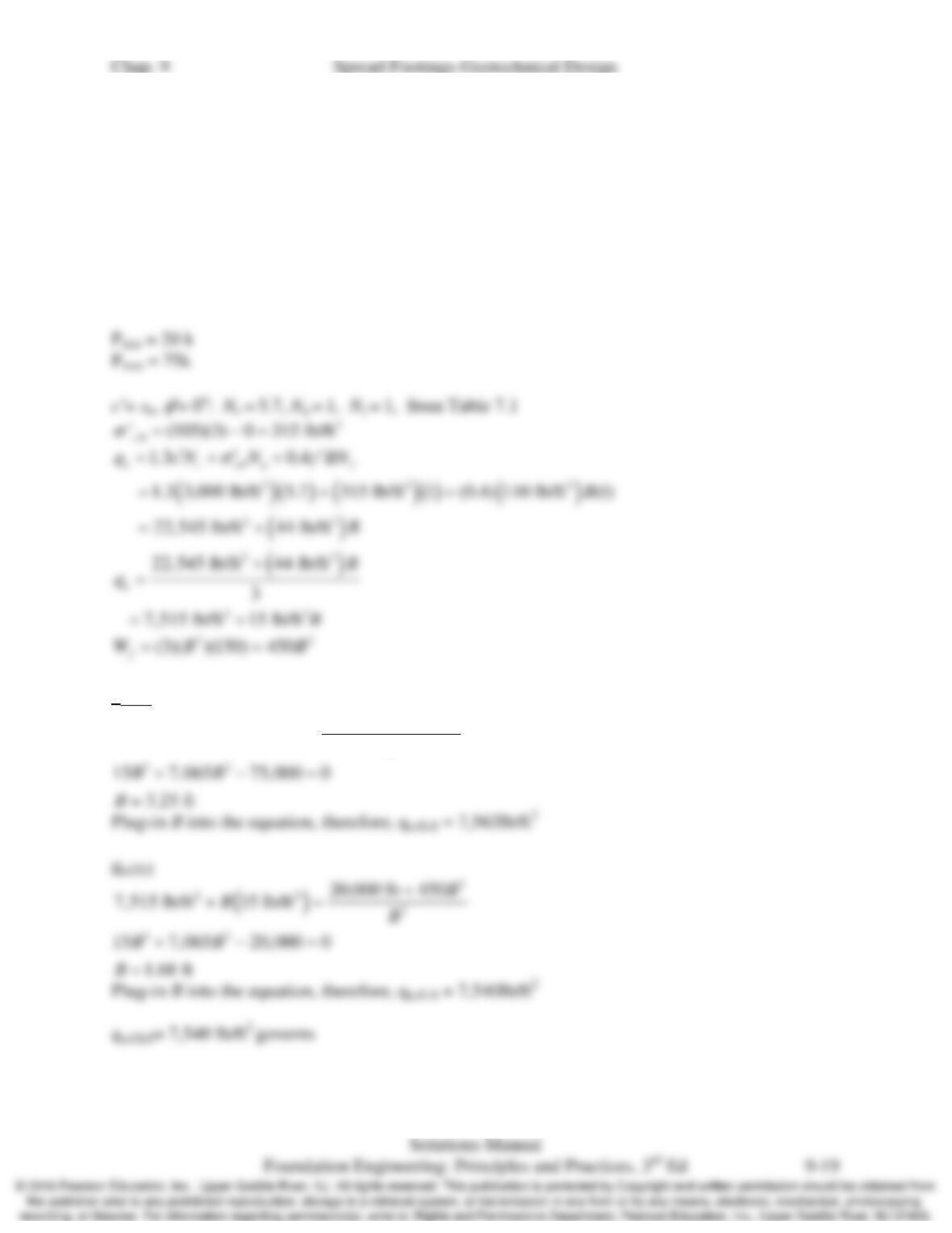
9.12 A series of columns carrying unfactored vertical loads of 20 to 90 k and service loads from 20 to
75 k are to be supported on 3-ft deep square footings. The soil below is a clay with the following
engineering properties: γ = 105 lb/ft3 above the groundwater table and 110 lb/ft3 below, su=
3000 lb/ft2, Cr/(1+e0) = 0.03 in the upper 10 ft and 0.05 below. Both soil strata are heavily
overconsolidated. The groundwater table is 5 ft below the ground surface. The factor of safety
against a bearing capacity failure must be at least 3. Determine the allowable bearing pressure,
qA, using ASD.
Solution
qa,SLS
( )
2
22
2
75,000 lb 450
7515 lb/ft 15 lb/ft
B
BB
+
+=
Chap. 9 Spread Footings-Geotechnical Design
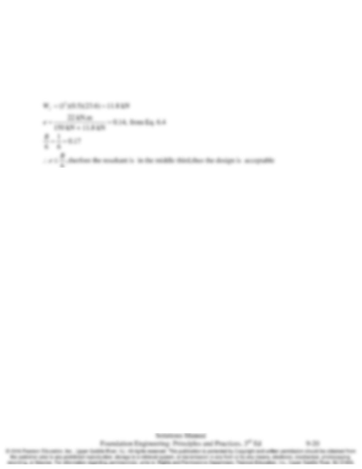
9.13 A square spread footing with B = 1 m and D = 0.5 m supports a column with the following ASD
design loads: P = 150 kN, M = 22 kN-m. The underlying soil has an allowable bearing pressure
of 200 kPa. Is this design acceptable? If not, compute the minimum required footing width and
express it as a multiple of 100 mm.
Solution
6