Problem 8.45
H. Blasius correlated data on turbulent friction factor in smooth pipes. His equation
14
0.3164 Re−
≈
smooth
f is reasonably accurate for Reynolds numbers between 4000 and 5
1
0.
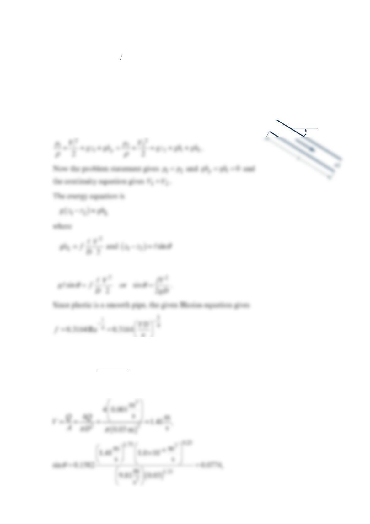
Use this information for the following scenario. Water at 20 C° is to flow through a 3-cm
I.D. plastic pipe at the rate of 3
0.001 m / s. Find the incline angle of the pipe needed to
make the static pressure constant along the pipe.
Solution 8.45
Apply the mechanical energy equation from 1 to 2.
so
ν
so
ν
θ
=
1.75 0.25
1.25
sin 0.1582 .
V
gD
The numerical values give
1•
ϕ
and
θ
=4.44; inclined downward in the direction of flow.
Checking the Reynolds number gives
Problem 8.46
Von Karman suggested that the wholly turbulent friction factor be expressed by the
equation
ε
=
−
2
1
40.57 log
f
D
where
ε
is the absolute roughness of the pipe. Compare the values predicted by this
equation and those indicated on the Moody chart.
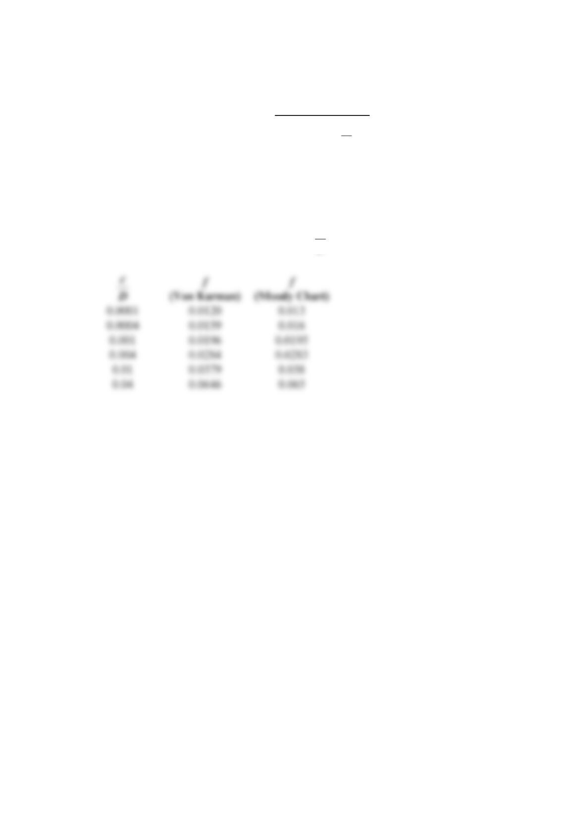
Solution 8.46
Choosing six values of the relative roughness,
ε
D, gives the following:
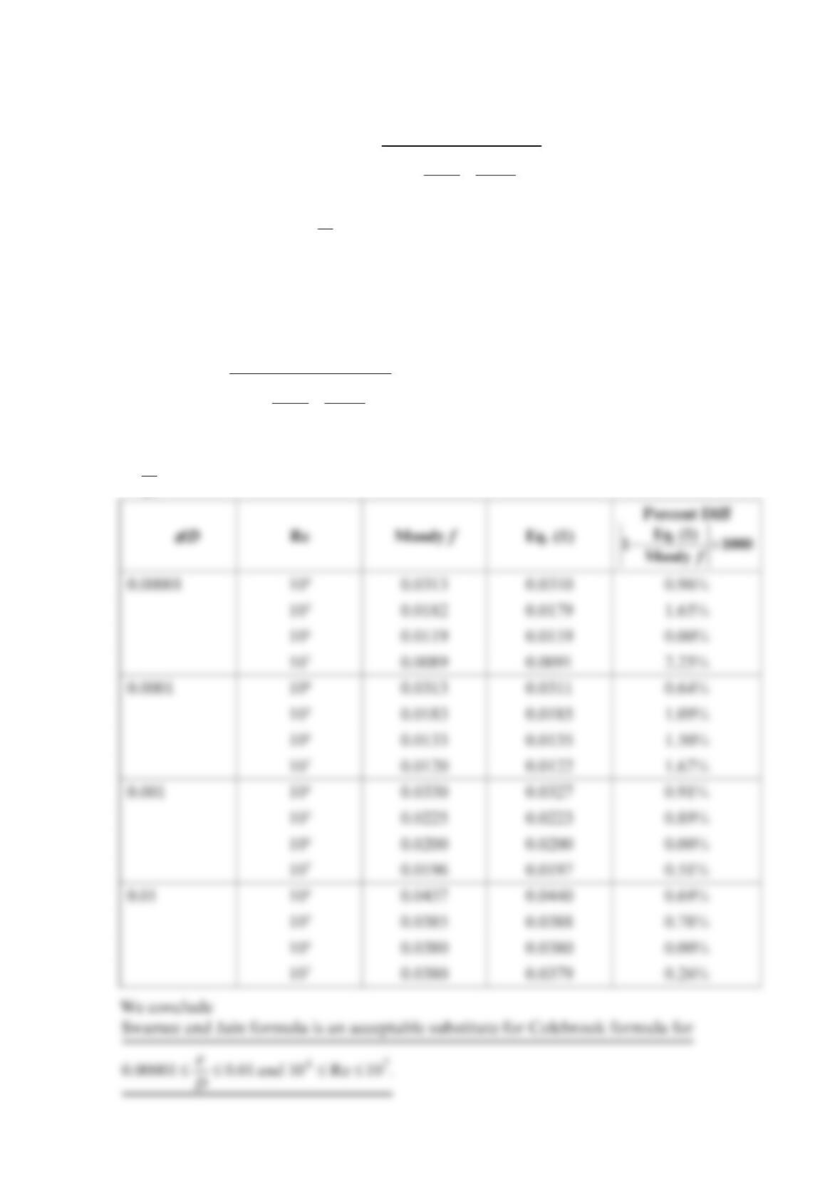
Problem 8.47
The Swamee and Jain formula for the friction factor is
ε
=
+
2
0.9
0.25 .
5.74
log 3.7 Re
f
D
Compare this equation for
ε
=0.00001
D, 0.0001, 0.001, and 0.01 and Reynolds numbers
of 456
10 , 10 , 10 , and 7
10 with the Moody chart and decide whether it is an acceptable
replacement for the Colebrook formula.
Solution 8.47
ε
=
+
2
0.9
0.25
5.74
log 3.7 Re
f
D
(1)
Tabulate the friction factor f from both the Moody chart and Eq. (1) for the above values
of
ε
D and Re .
Problem 8.48
The Haaland formula for the friction factor is
2
1.11
0.3086
6.9
log
Re 3.7
ε
=
+
f
D
.
Compare this equation for ffor
ε
=0.00001
D, 0.0001, 0.001, and 0.01 and Reynolds
numbers of 456
10 , 10 , 10 , and 7
10 with the Moody chart and decide whether it is an
acceptable replacement for the Colebrook formula.
Solution 8.48
We will tabulate the friction factor from both the Moody chart and Eq. (1) for the above
values of
ε
D and Re .
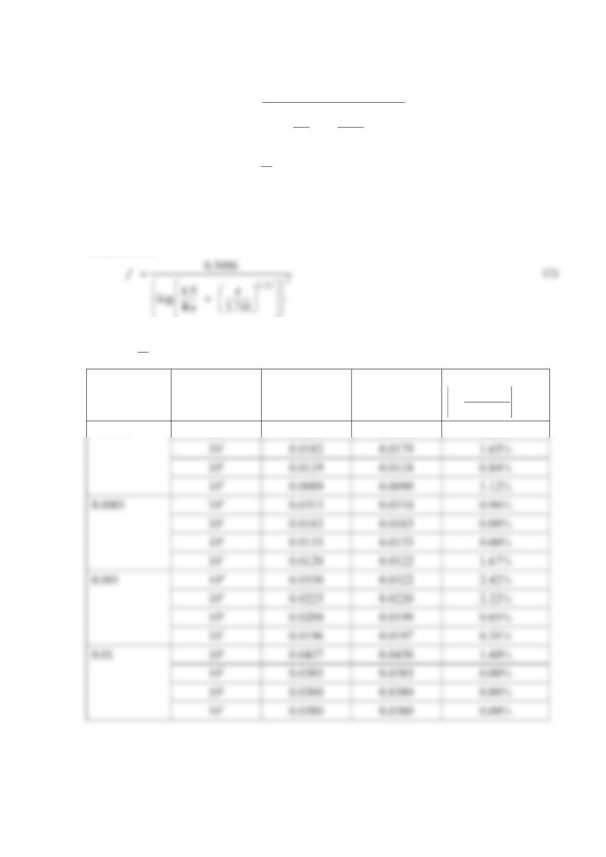
ε
/D Re Moody f Eq. (1) Percent Diff
−×
Eq. (1)
11000
Moody f
0.00001 104 0.0313 0.0309 1.28%

We conclude
Problem 8.49
The Churchill formula for the friction factor is
()
=+
+
1
12 12
1.5
81
8Re
f
AB
,
where
ε
=− +
16
0.9
7
2.457 ln Re 3.7
AD;
=
16
37530
Re
B.
Compare this equation for f for both the laminar and turbulent regimes for
0.00001, 0.0001, 0.001, and 0.01,
D
ε
= and Reynolds numbers of
23456 7
10, 10 , 10 , 10 , 10 , 10 , and 10 with the Moody chart and decide whether it is an
acceptable replacement for the Colebrook formula.
Solution 8.49
We will tabulate the friction factor from both the Moody chart and the Churchill formula
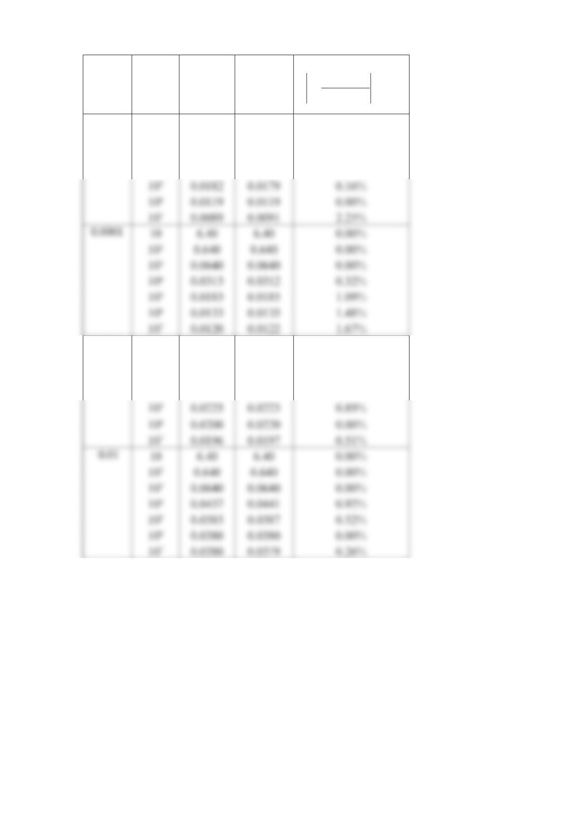
ε
/D Re Moody f Church. f
Percent Diff
−×
Church.
1 100
Moody
f
f
0.00001 10 6.40 6.40 0.00%
10² 0.640 0.640 0.00%
10³ 0.0640 0.0640 0.00%
104 0.0313 0.0310 0.96%
0.001 10 6.40 6.40 0.00%
102 0.640 0.640 0.00%
103 0.0640 0.0640 0.00%
104 0.0330 0.0327 0.91%
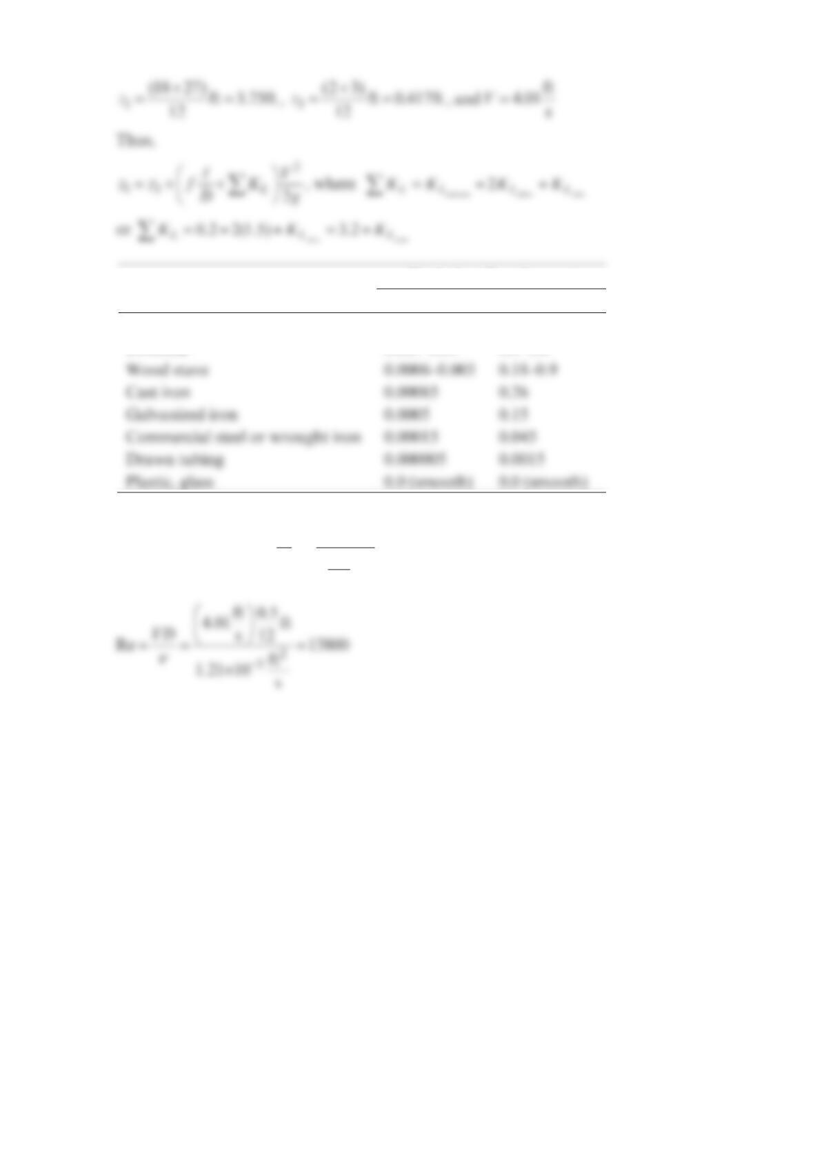
Problem 8.50
Air at standard temperature and pressure flows through a 1-in.– diameter galvanized iron
pipe with an average velocity of ft
8
s. What length of pipe produces a head loss equivalent
to (a) a flanged 90 elbow, (b) a wide-open angle valve, or (c) a sharp-edged entrance?
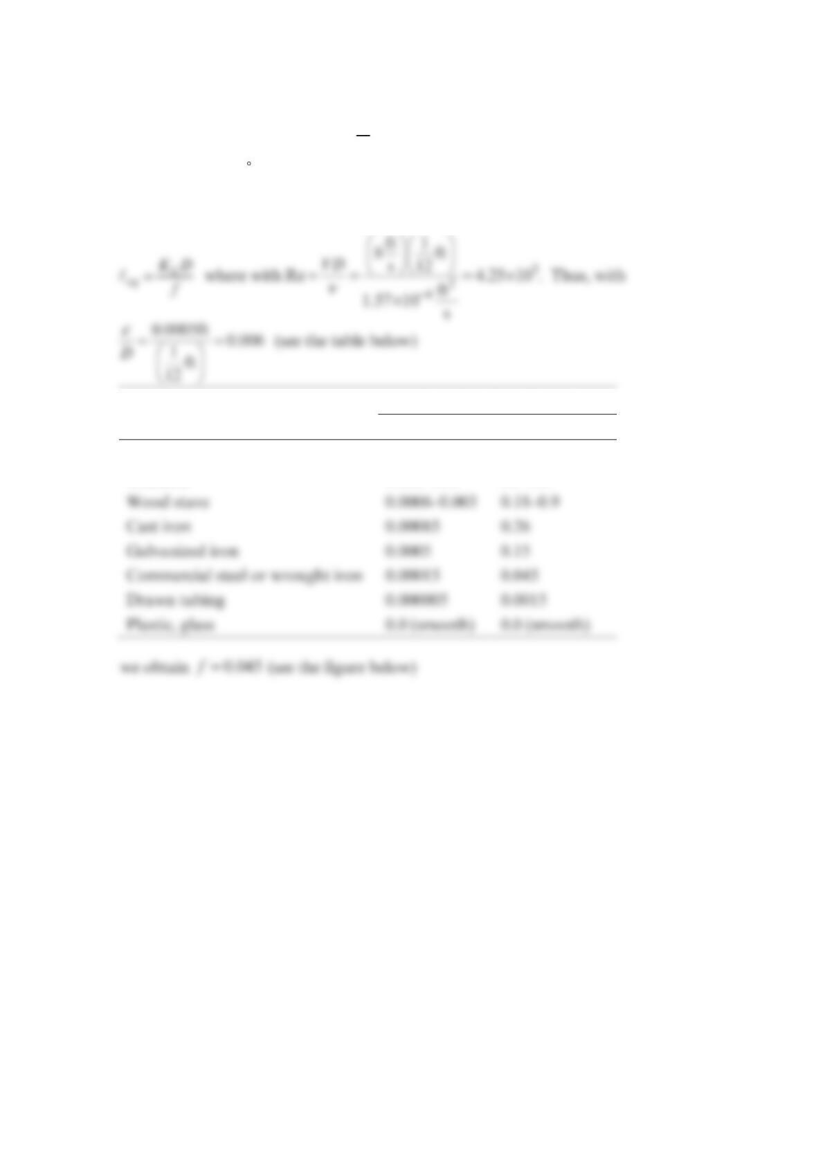
Solution 8.50
Equivalent Roughness,
ε
Pipe Feet Millimeters
Riveted steel 0.003–0.03 0.9–9.0
Concrete 0.001–0.01 0.3–3.0
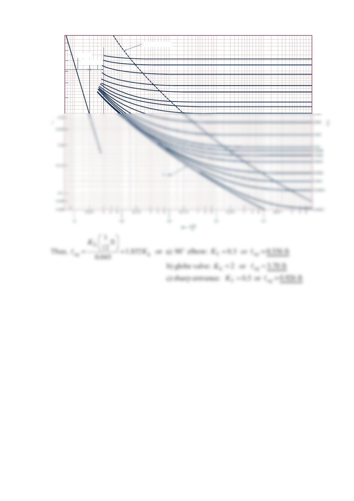
Transition range
Laminar flow
Wholly turbulent flow
0.1
0.09
0.08
0.07
0.06
0.05
0.04
0.05
0.04
0.03
0.02
0.015
0.01
0.008
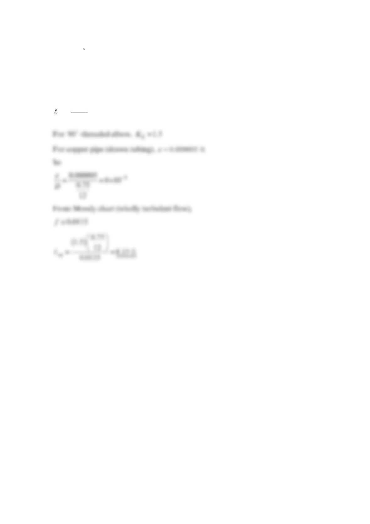
Problem 8.51
Given 90 threaded elbows used in conjunction with copper pipe (drawn tubing) of
0.75–in. diameter, convert the loss for a single elbow to equivalent length of copper pipe for
wholly turbulent flow.
Solution 8.51
=L
eq
KD
f
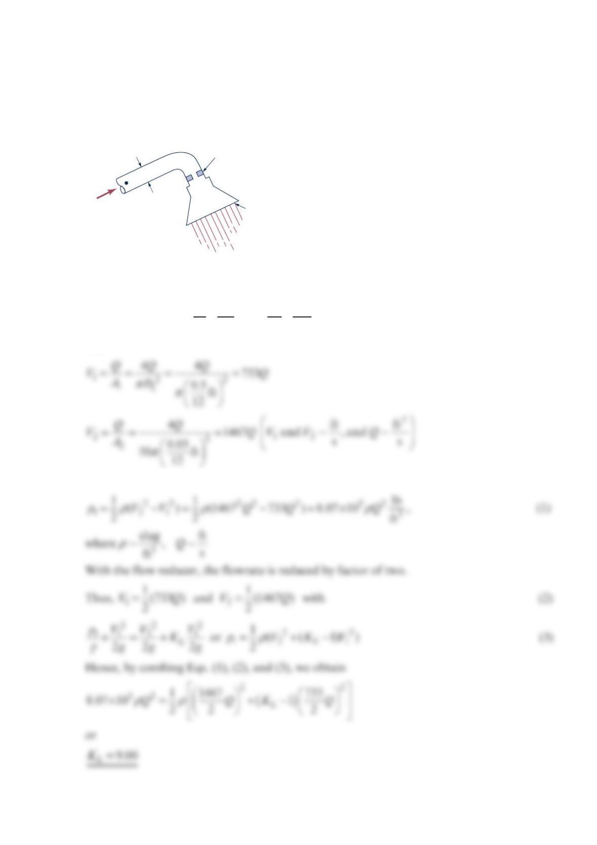
Problem 8.52
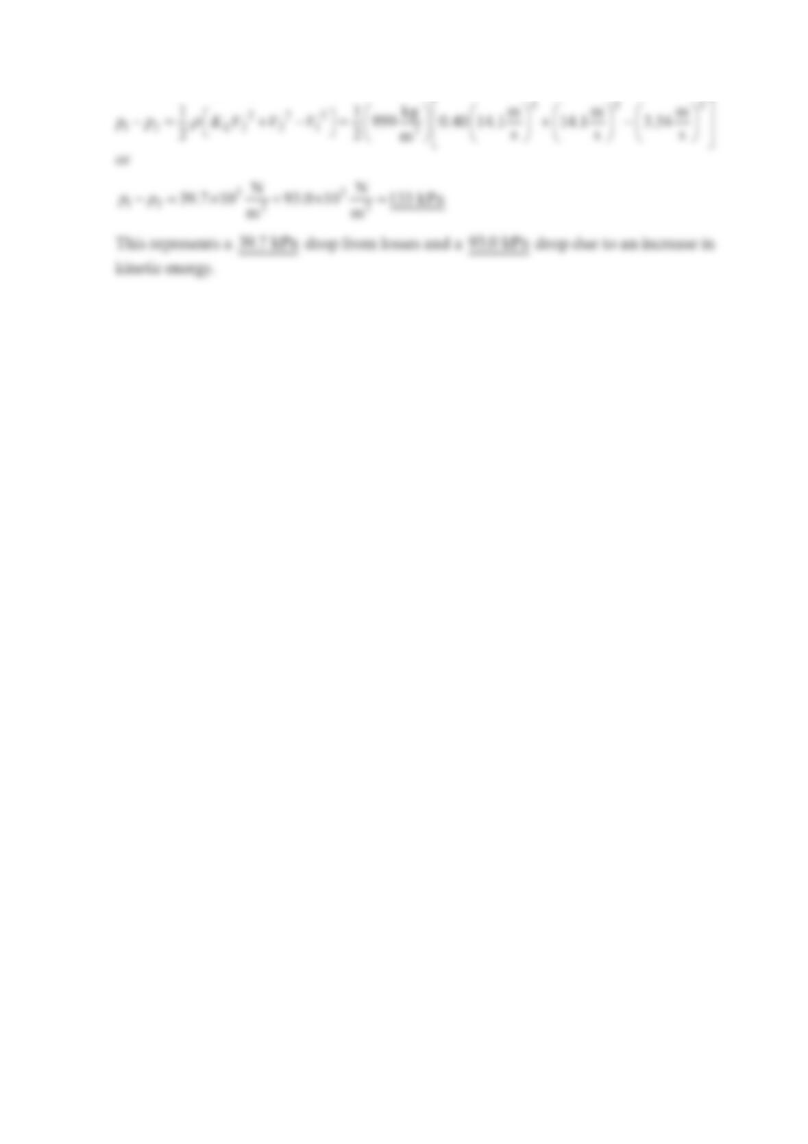
To conserve water and energy, a “flow reducer” is installed in the shower head as shown in
the figure below. If the pressure at point
(
1) remains constant and all losses except for that
in the flow reducer are neglected, determine the value of the loss coefficient (based on the
velocity in the pipe) of the flow reducer if its presence is to reduce the flowrate by a factor
of 2. Neglect gravity.
Solution 8.52
Without the reducer
γγ
++=+ +
22
11 2 2
12
,
22
pV p V
zz
gg
where ==
212
0,
p
zz
and
Thus,
Q
1
__
2in.
(1)
Flow reducer washer
50 holes of
diameter 0.05 in.
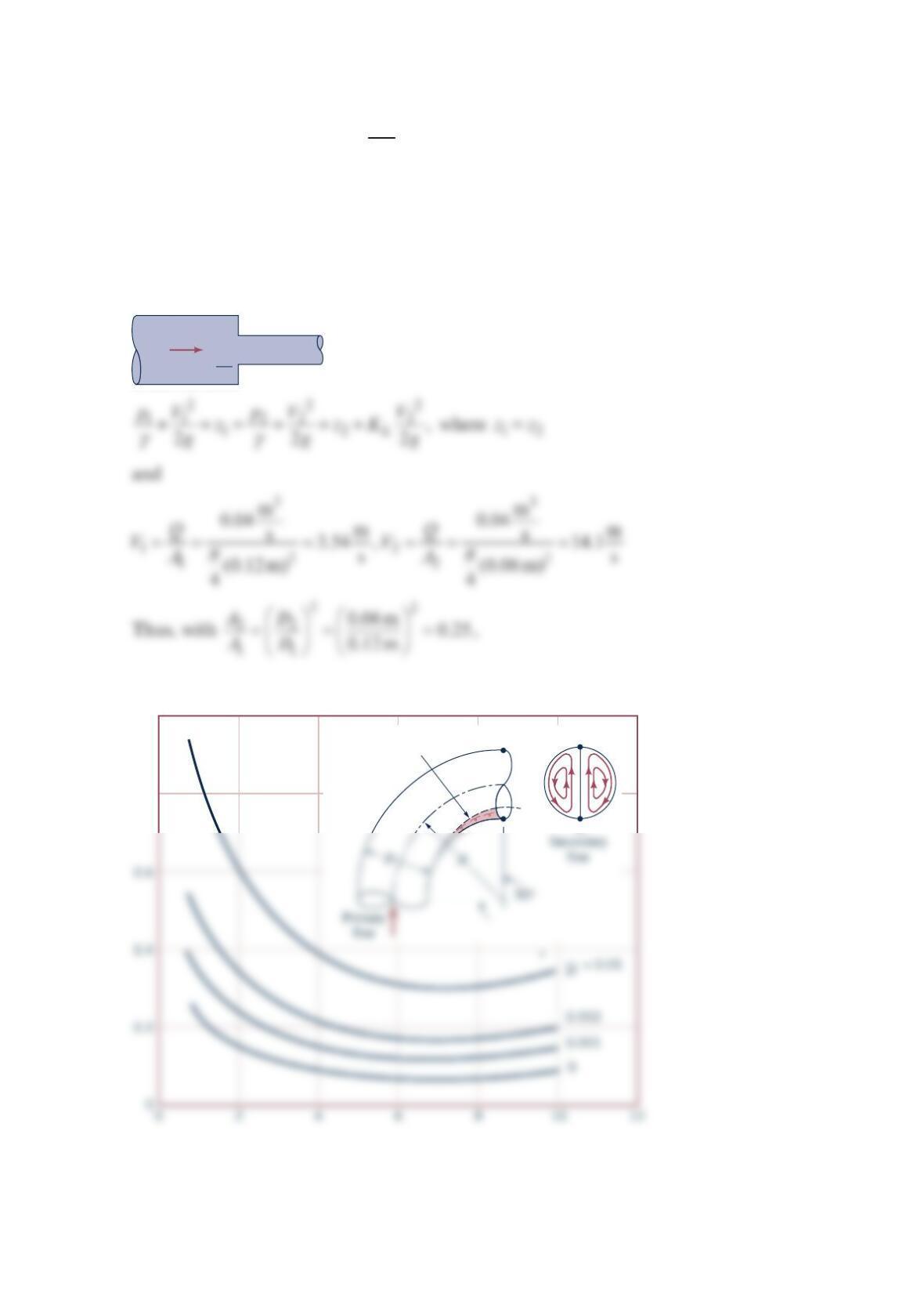
Problem 8.53
Water flows at a rate of
3
m
0.040 s in a 0.12-m– diameter pipe that contains a sudden
contraction to a 0.06-m– diameter pipe. Determine the pressure drop across the contraction
section. How much of this pressure difference is due to losses and how much is due to
kinetic energy changes?
Solution 8.53
we obtain from the figure below =0.40
L
K
D
1
= 0.12 m
D
2
= 0.06 m
Q
= 0.04
• (2)
•
(1)
s
m
3
Separated flow
bb
a
a
1.0
0.8
ℛ
/
D
Hence, from Eq. (1),
Problem 8.54
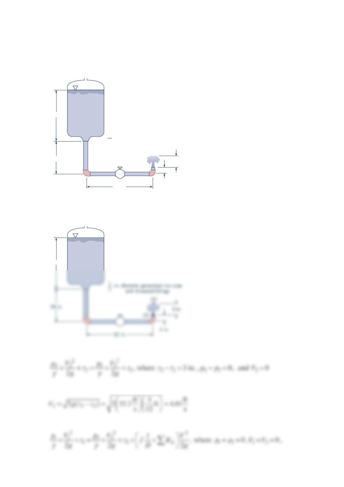
Water flows from the container shown in the figure below. Determine the loss coefficient
needed in the valve if the water is to “bubble up” 3 in. above the outlet pipe. The entrance
is slightly rounded.
Solution 8.54
Determine the outlet velocity from Bernoulli equation:
Thus,
Also,
Vent
-in.-diameter galvanized iron pipe
with threaded fittings
32 in.
2 in.
3 in.
1
2
18 in.
27 in.
Vent
27 in.
(1)
•
Equivalent Roughness,
ε
Pipe Feet Millimeters
Riveted steel 0.003–0.03 0.9–9.0
Concrete 0.001–0.01 0.3–3.0
From the table above,
ε
==
0.0005ft 0.012,
0.5 ft
12
D and
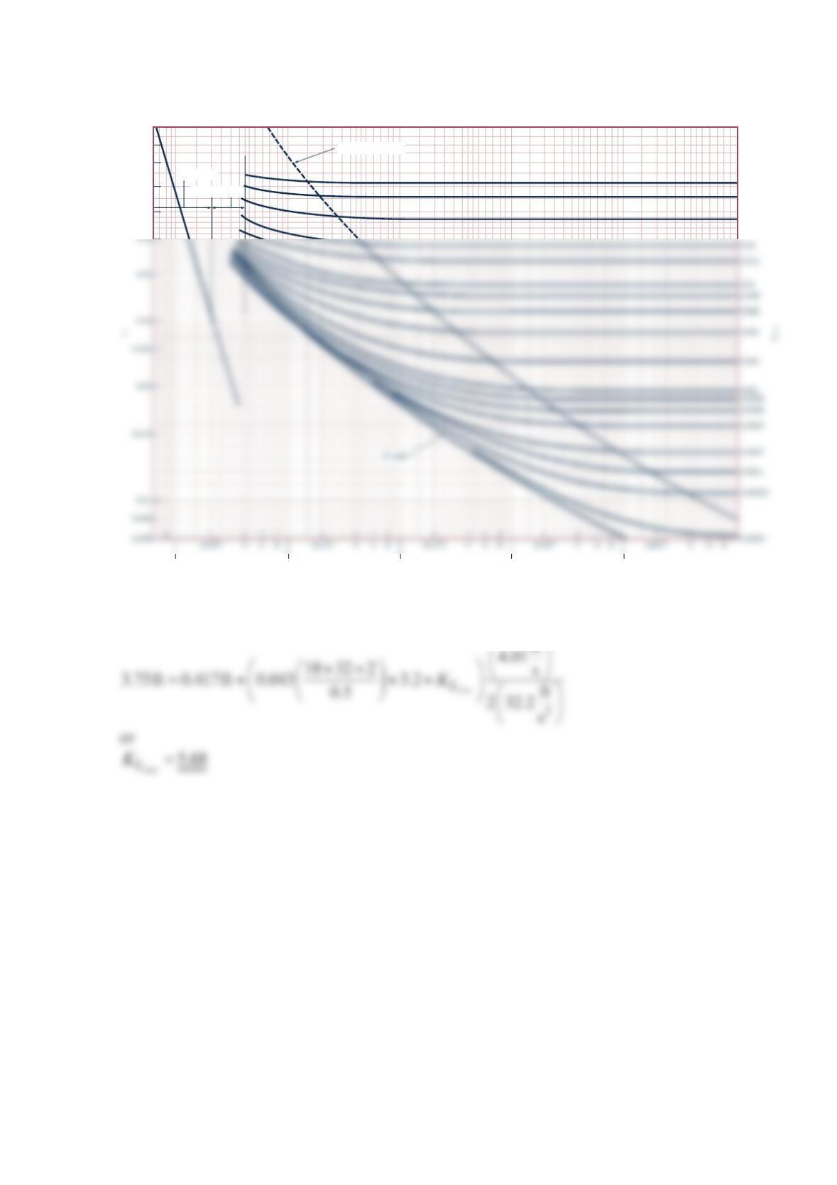
Thus, from the figure below, =0.043f
Hence,
2
Transition range
Laminar flow
Wholly turbulent flow
0.1
0.09
0.08
0.07
0.06
103
104
105
106
107
0.05
0.04
0.03
Re = VD
_____
μ
ρ
Problem 8.55
New hi-tech fountains Ancient Egyptians used fountains in their palaces for decorative and
cooling purposes. Current use of fountains continues but with a hi-tech flair. Although the
basic fountain still consists of a typical pipe system (i.e., pump, pipe, regulating valve, nozzle,
filter, and basin), recent use of computer-controlled devices has led to the design of
innovative fountains with special effects. For example, using several rows of multiple nozzles,
it is possible to program and activate control valves to produce water jets that resemble
symbols, letters, or the time of day. Other fountains use specially designed nozzles to produce
coherent, laminar streams of water that look like glass rods flying through the air. Using fast-
acting control valves in a synchronized manner it is possible to produce mesmerizing three-
dimensional patterns of water droplets. The possibilities are nearly limitless. With the initial
artistic design of the fountain established, the initial engineering design (i.e., the capacity and
pressure requirements of the nozzles and the size of the pipes and pumps) can be carried out.
It is often necessary to modify the artistic and/or engineering aspects of the design in order to
obtain a functional, pleasing fountain. (See Problem 8.55.)
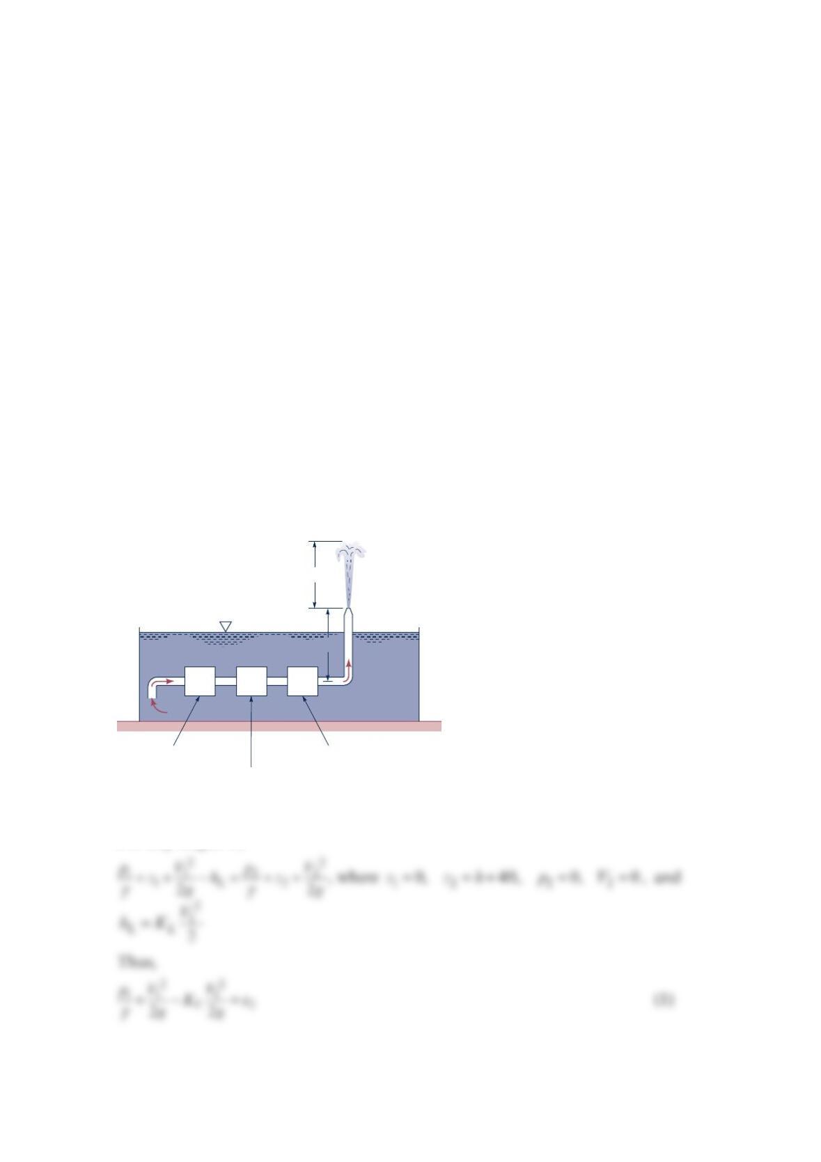
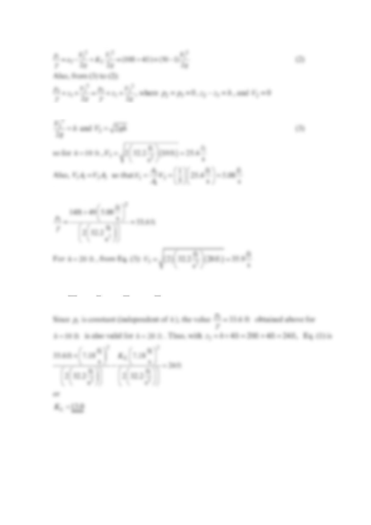
The fountain shown in the figure below is designed to provide a stream of water that rises
=10 fth to =20 fth above the nozzle exit in a periodic fashion. To do this, the water from
the pool enters a pump, passes through a pressure regulator that maintains a constant
pressure ahead of the flow control valve. The valve is electronically adjusted to provide the
desired water height. With =10 fth, the loss coefficient for the valve is =50
L
K. Determine
the valve loss coefficient needed for =20 fth. All losses except for the flow control valve
are negligible. The area of the pipe is 5 times the area of the exit nozzle.
Solution 8.55
For any height h,
4 ft
Pump Flow control valve
Pressure regulator
h
For =10fth: =(50)
L
K
Thus,
Hence, Eq. (2) gives
Hence,
== =
3
13
1
1ft ft
35.9 7.18
5s s
A
VV
A
Problem 8.56
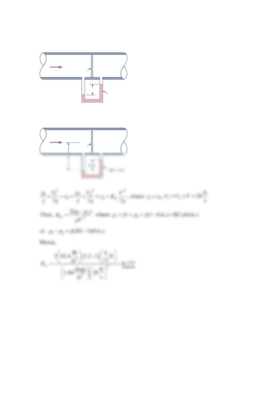
Water flows through the screen in the pipe shown in the figure below as indicated.
Determine the loss coefficient for the screen.
Solution 8.56
V
= 20 ft/s
SG
= 3.2
Water
Screen
6 in.
V
= 20 ft/s
Water
Screen
(1)
•(2)
•