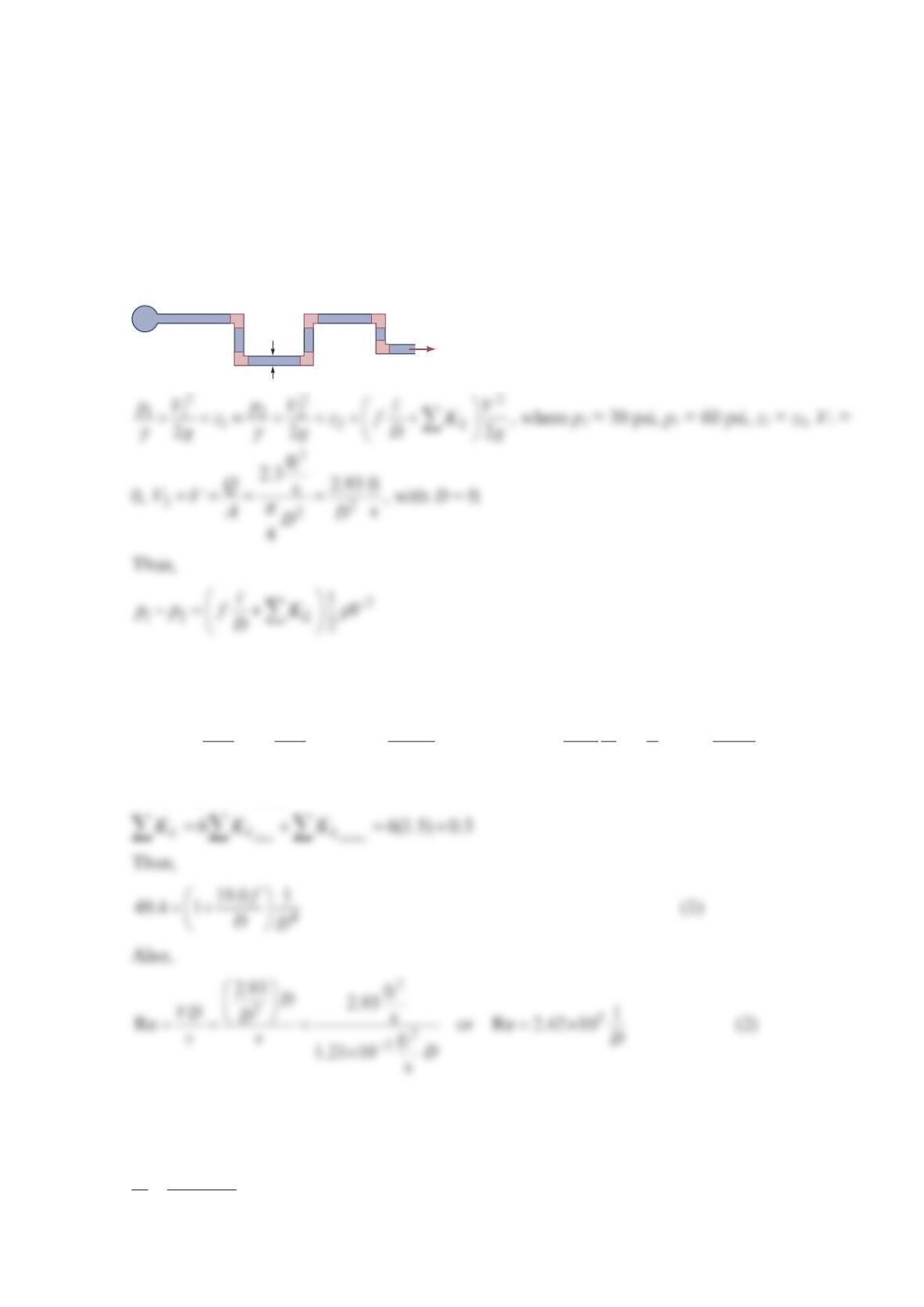
Problem 8.101
A certain process requires 2.3 cfs of water to be delivered at a pressure of 30 psi. This water
comes from a large-diameter supply main in which the pressure remains at 60 psi. If the
galvanized iron pipe connecting the two locations is 200 ft long and contains six threaded
90° elbows, determine the pipe diameter. Elevation differences are negligible.
Solution 8.101
or
−=+++
2
2
22 2 3
lb in. 200 ft 2.93 ft 1 s1ugs
(60 30) 144 (1 6(1.5) 0.5) 1.94
s2
in. ft ft
fDD
where we have used
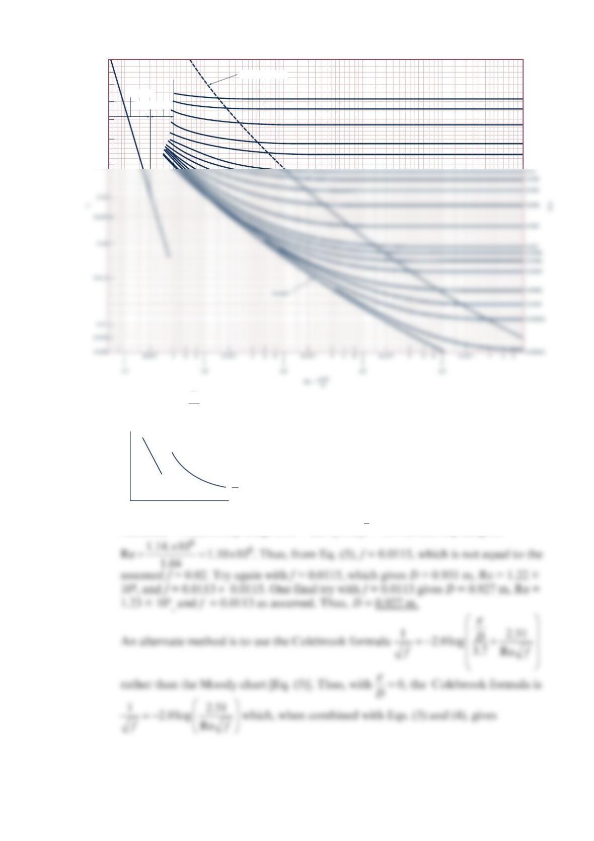
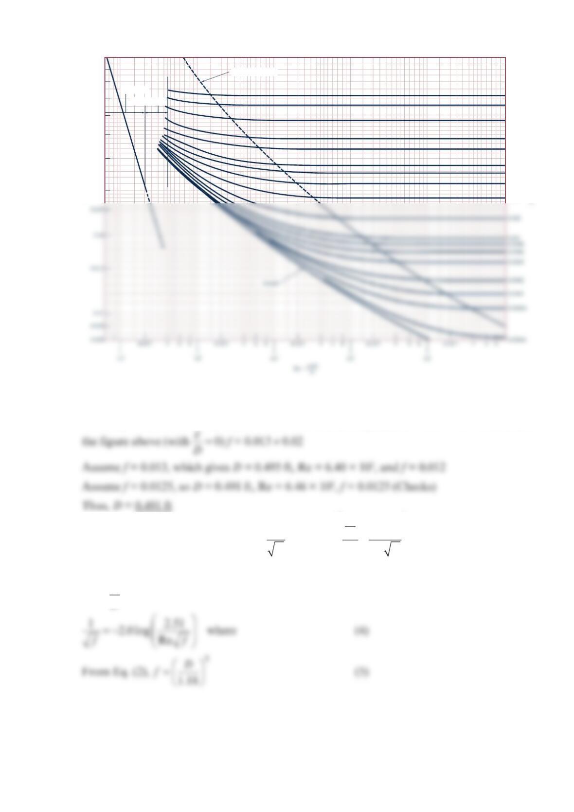
and from Table B.1 Equivalent Roughness for New Pipes [Adapted from Moody (Ref. 7)
and Colebrook (Ref. 8)]
0.0005 ft
DD
ε
= (3)
(2)
(1)
•
D
Q
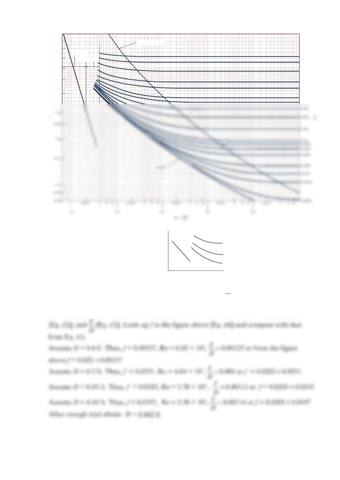
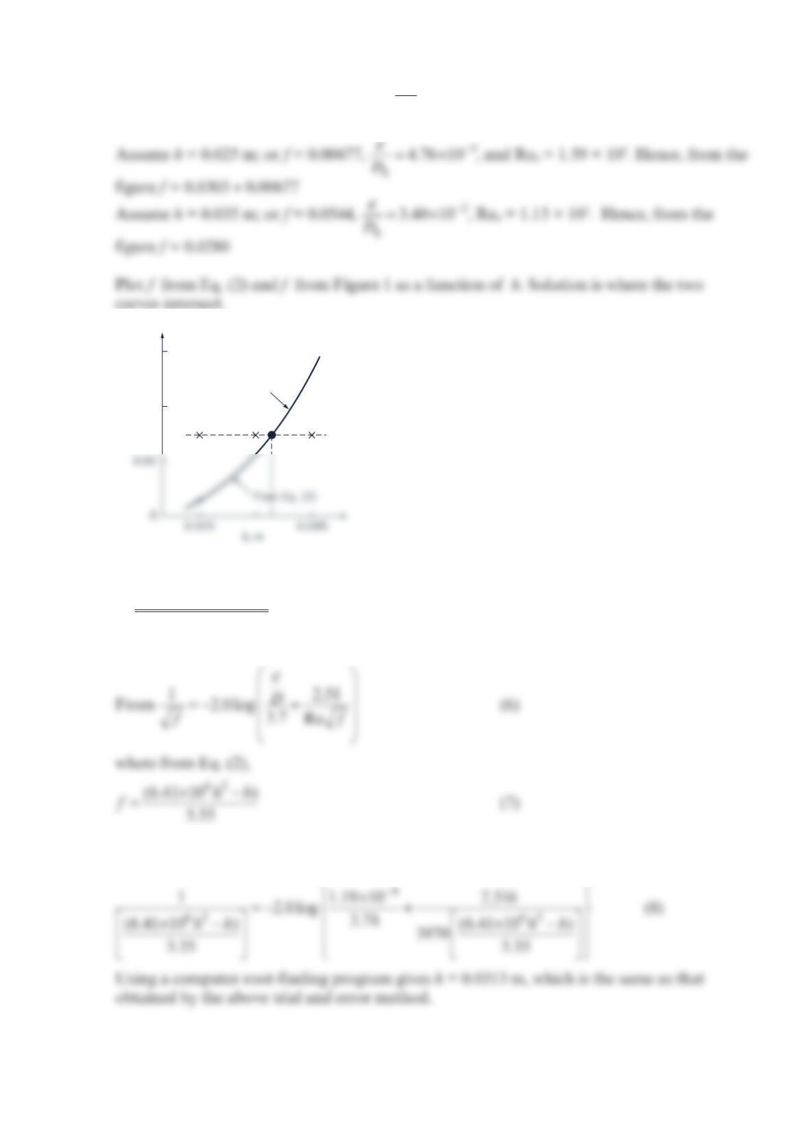
Finally, from the figure above:
(4)
Trial and error solution of Eqs. (1), (2), (3), and (4) for f, D, D
ε
, and Re.
Normally, it is easiest to guess a value of f, calculate D, etc. In this case (because of minor
losses), Eq. (1) is not easy to use in this fashion. Thus, assume D, calculate f [Eq. (1)], Re
Transition range
Laminar flow
Wholly turbulent flow
0.1
0.09
0.08
0.07
0.06
0.05
0.04
0.05
0.04
0.03
0.02
0.015
0.01
0.008
D
f
Note: If the figure above [Eq. (4)] is replaced by the Colebrook equation, this problem can
be solved as follows.
Thus, from Eq. (1),
combined with Eqs. (2) and (3), gives
Problem 8.102
Water is pumped between two large open reservoirs through 1. 5 km of smooth pipe. The
water surfaces in the two reservoirs are at the same elevation. When the pump adds 20 kW
to the water, the flowrate is
3
m
1
s. If minor losses are negligible, determine the pipe
diameter.
Solution 8.102
22
11 2 2
12
22
sL
pV p V
zhh z
gg
γγ
++ +− = + + , where 12
0
p
p==
, 12
0
V
V==
, 12
zz=
Thus,
Hence,
(2)
×
==
22
322
5
2
1.23 m
1.5 10 m s123.9 m
m
29.81
s
L
f
D
hf DD
(1)
•
PUMP
(2)
•
V
Finally, with 0
D
ε
=, the Moody chart (the figure above) is the final equation.
(5)
Trial and error solution of Eqs. (3), (4), and (5) for f, Re,
and D:
Assume f = 0.02, so Eq. (3) gives
()
==
1
5
2.27 0.02 1.04 m
D
and Eq. (4) gives
Transition range
Laminar flow
Wholly turbulent flow
0.1
0.09
0.08
0.07
0.06
0.05
0.04
0.05
0.04
0.03
0.02
0.015
Re
f
= 0
D
ε

(6)
=−
11
12.51
2.0 log
D
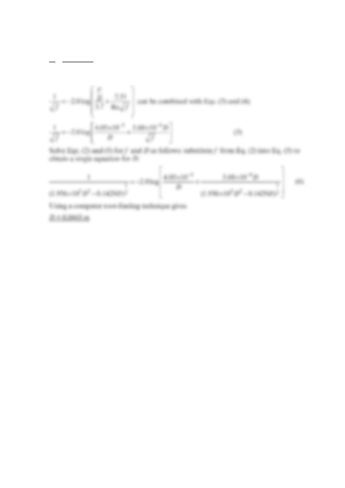
Problem 8.103
Determine the diameter of a steel pipe that is to carry gal
2000 min
of gasoline with a pressure
drop of 5 psi per 100 ft of horizontal pipe.
Solution 8.103
22
2
11 2 2
12
222
pV p V V
zzf
ggDg
γγ
++=+++
, where z1 = z2, and V1 = V2
Thus,
4
Hence, Eq. (1) gives:
=
2
232
lb 100 ft 1 slug 5.67 ft
5(144) 1.32
ft 2 s
ft ft
fDD
or
Note: Four equations [Eqs. (2), (3), (4), and (5)] and four unknowns ( f, D
ε
, D, and Re)
Trial and error solution:
Thus,
1
5
1.24(0.0150) 0.535 ft
D
==
Using the Colebrook equation, rather than the Moody chart, Eq. (5), we have
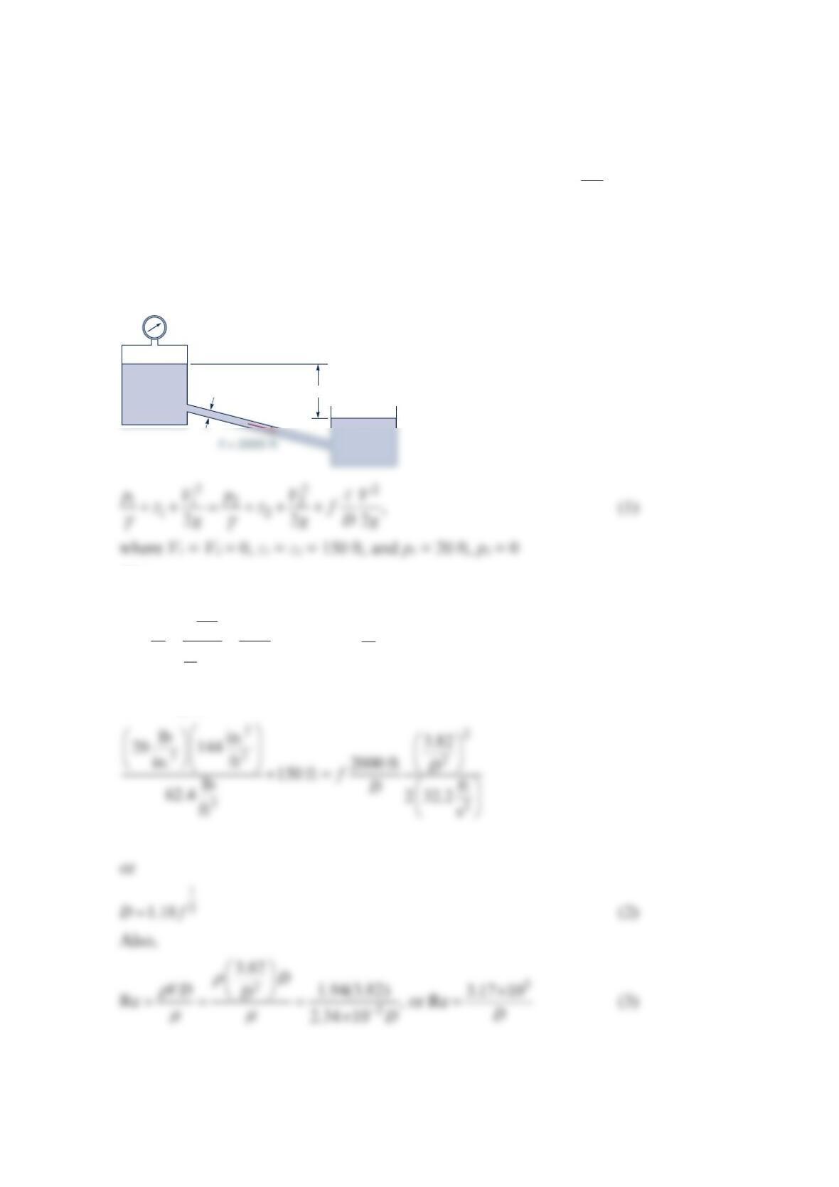
Problem 8.104
Water is to be moved from a large, closed tank in which the air pressure is 20 psi into a
large, open tank through 2000 ft of smooth pipe at the rate of
3
ft
3s. The fluid level in the
open tank is 150 ft below that in the closed tank. Determine the required diameter of
the pipe. Neglect minor losses.
Solution 8.104
Also,
π
== =
3
2
2
ft
33.82
s
4
Q
VAD
D
, where ft
~s
V, D ~ ft
Thus, Eq. (1) becomes
(1)
•
(2)
•
V
D
150 ft
Trial and error solution:
Assume f = 0.02 so from Eq. (2), D = 0.540 ft and from Eq. (3), Re = 5.87 × 10⁵. Thus, from
Alternately, the Colebrook equation, 12.51
2.0 log 3.7 Re
D
ff
ε
=− +
, rather than the Moody
chart, the figure above, could be used as follows:
With 0
D
ε
=, the Colebrook equation is
Transition range
Laminar flow
Wholly turbulent flow
0.1
0.09
0.08
0.07
0.06
0.05
0.04
0.03
0.05
0.04
0.03
0.02
0.015
0.01
0.008
0.006
0.004
_
_
ε
f
Thus, combining Eqs. (3), (4), and (5) gives
12.51
Problem 8.105
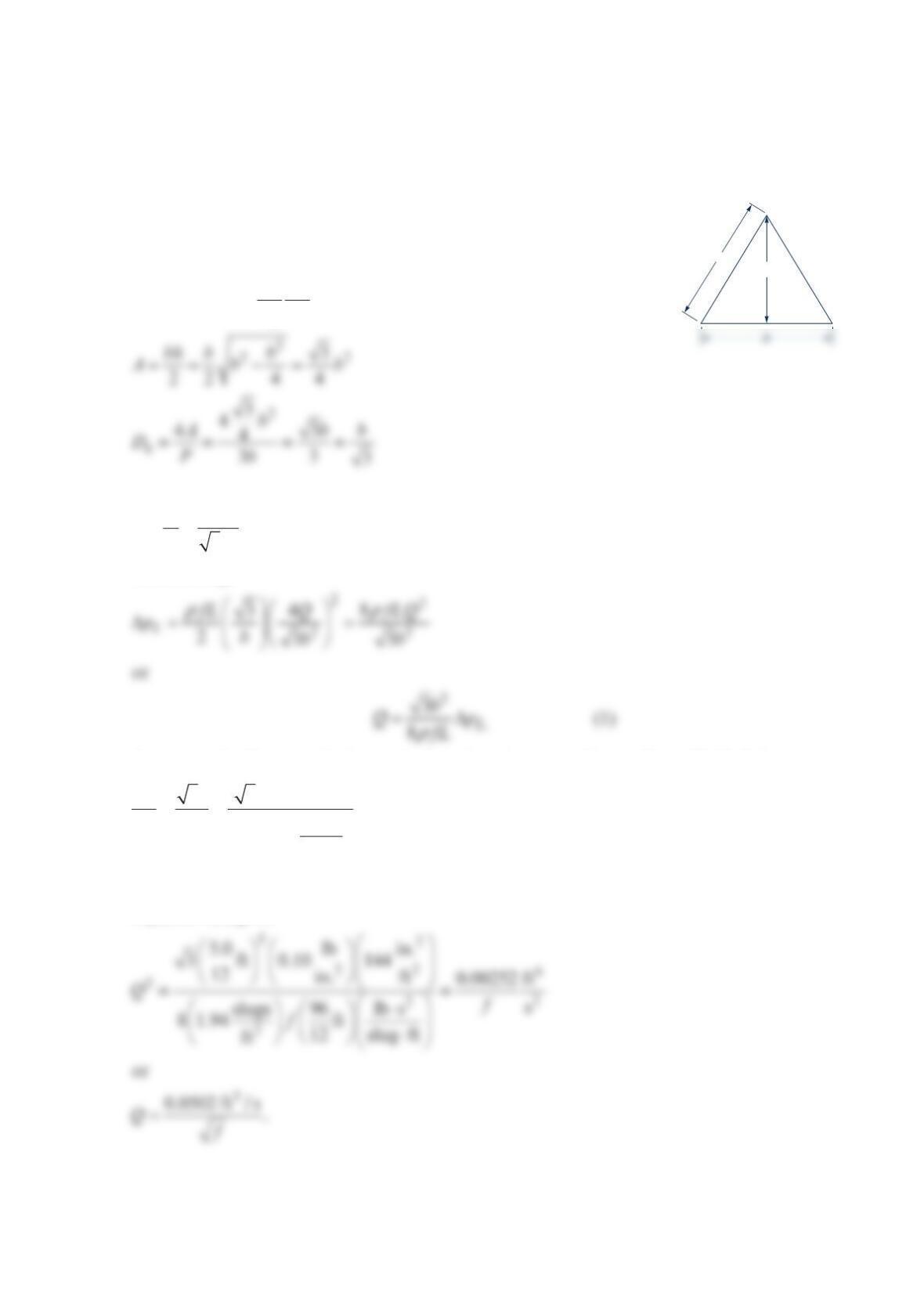
A commercial steel flow channel in a heat exchanger has an equilateral triangle cross
section with each side measuring 5.0 in. and a length measuring 96.0 in. Water at 60 °F
flowing through the channel has a pressure loss of 0.10 psi. Find the water flowrate.
Solution 8.105
The pressure loss is
2
.
2
LL
h
f
LV
pgh D
ρρ
Δ
==
2
4
3
QQ
V
Ab
==
Substituting,
Assuming the flow is turbulent, calculate the relative roughness. Using Table 8.1,
3 3(0.00015 ft) 0.000624.
ft
(5.0 in.) 12 in.
h
Db
εε
== =
Equation (1) gives
h
b
The Reynolds number is
3
52
5
44(ft/s)
Re 2.64 10 .
35
3ft1. ft
21 10
2s1
QQ Q
bv −
== =×
×
We now guess Q = 0.375 ft3/s. Then
Our second guess is Q = 0.375 ft3/s. Then,
54
Re 2.64 10 (0.345) 9.11 10=× =×
.
The Moody chart gives f = 0.0211 so
Problem 8.106
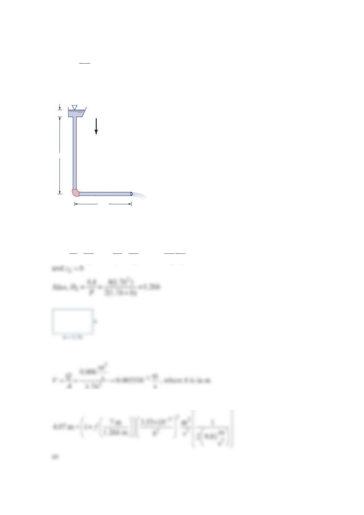
Rainwater flows through the galvanized iron downspout shown in the figure below at a rate
of
3
m
0.006 s. Determine the size of the downspout cross section if it is a rectangle with an
aspect ratio of 1.7 to 1 and it is completely filled with water. Neglect the velocity of the
water in the gutter at the free surface and the head loss associated with the elbow.
Solution 8.106
(1)
22 2
11 2 2
12
22 2
h
pV p V V
zzf
ggDg
γγ
++=+++
, where 12
0
p
p==
, 10
V
=, 21
V
V=, 14.07 mz=,
and
Thus, from Eq. (1),
g
70 mm
4 m
3 m
and
−
−
== =
×
2
62
m
0.00353 (1.26 m) 3970
s
Re or Re
1.12 10 m
s
h
hh
hh
VD
vh
(4)
Figure (1)
Finally, from Figure 1 above:
Trial and error solution of Eqs. (2), (3), (4), and Figure 1 for f, h, Reh,
D
ε
.
Transition range
Laminar flow
Wholly turbulent flow
0.1
0.09
0.08
0.07
0.06
0.05
0.04
0.03
Assume h = 0.03 m; from (2) f = 0.0227, 3
4.0 10
h
D
ε
−
=× , and Reh = 1.32 × 10⁵. Hence, from
the figure f = 0.0290 ≠ 0.0227
Thus, h = 0.031 m and b = 1.7 (0.031 m)
or 0.031 m by 0.053 m
This problem can be solved using the Colebrook equation, rather than the Moody chart,
Figure 1 above, as follows:
Combining Eqs. (3), (4), (6), and (7) gives a single equation for h:
0.04
0.06
•
f
From Eq. (5)
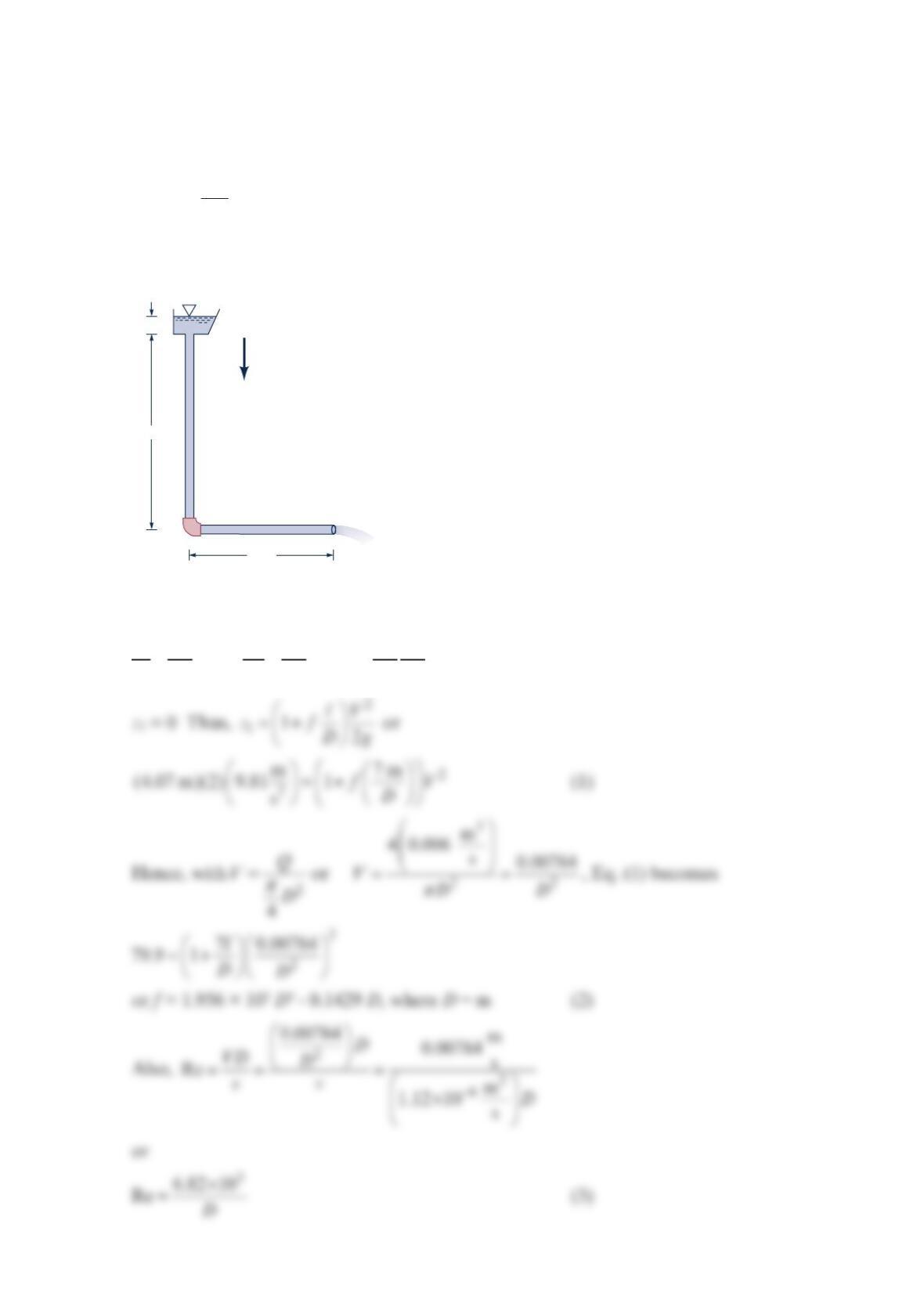
Problem 8.107
Rainwater flows through the galvanized iron downspout shown in the figure below at a rate
of
3
m
0.006 s. Determine the size of the downspout diameter if it is circular and it is
completely filled with water. Neglect the velocity of the water in the gutter at the free
surface and the head loss associated with the elbow.
Solution 8.107
22 2
11 2 2
12
22 2
h
pV p V V
zzf
ggDg
γγ
++=+++
, where 1
p
= 2
p
= 0, 1
V
= 0, 2
V
= 1
V
, 1
z = 4.07 m, and
g
70 mm
4 m
3 m
From Table 8.1 Equivalent Roughness for New Pipes [Adapted from Moody (Ref. 7) and
Colebrook (Ref. 8)]
ε
−
×
=
3
0.15 10
DD
(4)
so that the Colebrook equation,
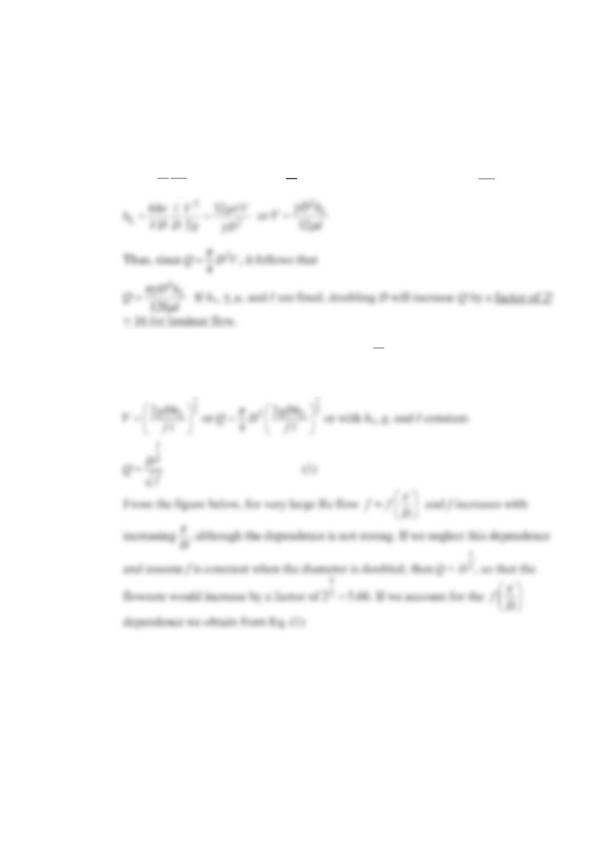
Problem 8.108
For a given head loss per unit length, what effect on the flowrate does doubling the pipe
diameter have if the flow is (a) laminar, or (b) completely turbulent?
Solution 8.108
(a)
2
2
L
V
h
fDg
=, where Re,
ε
=
ff D. Thus, for laminar flow with 64
Re
f=,
(b) For completely turbulent flow, f is a function of D
ε
only (not Re).
Thus,
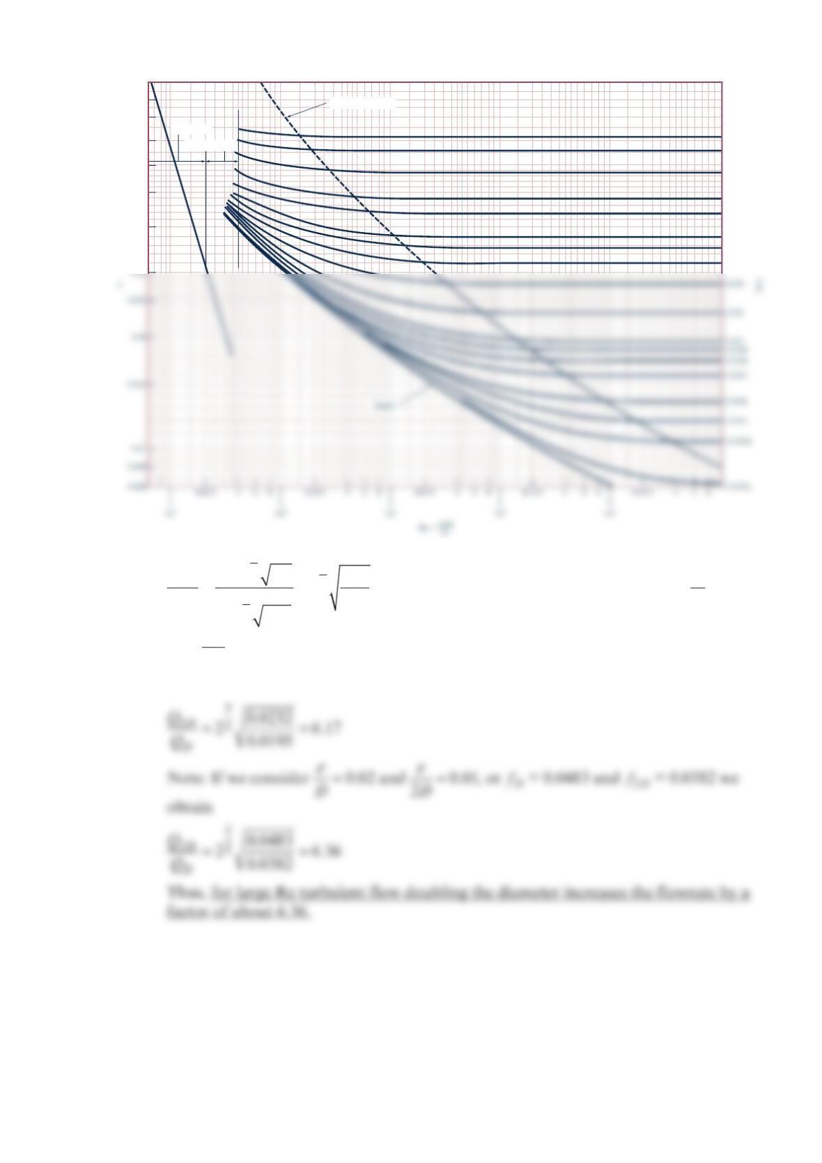
5
5
2
22
52
22
(2 ) 2
()
D
DD
DD
D
Df
Qf
Qf
Df
==
, where typical values for fD and f2D (i.e., with 0.002
D
ε
=
and
ε
=0.001
2D) for large Re are fD = 0.0232 and f2D = 0.0195
Thus,
Transition range
Laminar flow
Wholly turbulent flow
0.1
0.09
0.08
0.07
0.06
0.05
0.04
0.05
0.04
0.03
0.02
0.015
0.01
0.008
0.006