8-14 Groundwater—Multidimensional Flow and Applications Chap. 8
Section 8.5 Groundwater Control
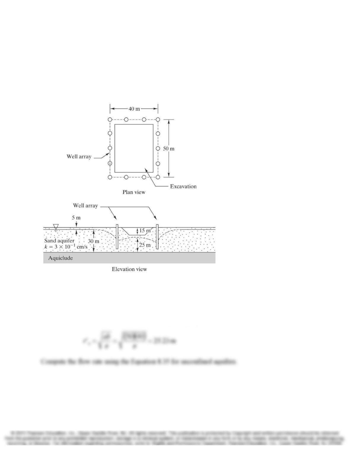
8.16 A construction site needs to be predrained in order to allow for the excavation shown in
Figure 8.44. This will require dropping the groundwater table 5 m below its current
location. From observations of the drawdown from other wells in the area, the radius of
influence, r0, is estimated to be 825 m. Compute the pumping rate required to lower the
groundwater table using the well array shown.
Figure 8.44 Plan and elevation drawing for Problem 8.16.
Solution
Compute the equivalent radius of the well array using Equation 8.42

Chap. 8 Groundwater—Multidimensional Flow and Applications 8-15
Section 8.6 Contaminant Control and Remediation
8.17 A contaminate soil site is to be capped and provided with a slurry wall barrier similar to
the situation shown in Figure 8.29. A bioremediation process will be used to clean up the
contaminated soil. This bioremediation process is expected to take 15 years. The slurry
wall must be designed to prevent migration of the contaminants off of the site during the
15 year bioremediation process. If the regional hydraulic gradient is 0.0043 from left to
right in Figure 8.29 and the clay in the slurry wall has a hydraulic conductivity (k) of
2×10⁻⁵ cm/s with an effective porosity (ne) of 65%, how thick does the slurry have to be
to contain the contaminants for 15 years?
Solution
Use Equation7.13 to compute the seepage velocity
=
e
sn
ki
v
Section 8.7 Soil migration and Filtration
8.18 A proposed levee is to be built using the soil described in Figure 8.45. This levee will
include a toe drain similar to the one in Figure 8.34 to control the groundwater flow, and
thus maintain adequate stability. This toe drain must be coarse enough to adequately
collect and transmit the water, yet fine enough to provide sufficient filtration to prevent
migration of the main levee soils. There will be no separate filter layer; the drain must
act as the filter.
8-16 Groundwater—Multidimensional Flow and Applications Chap. 8
To maintain sufficient hydraulic conductivity, the drain must have no more than 3%
passing the #200 sieve. In addition, to provide adequate filtration, it must meet the
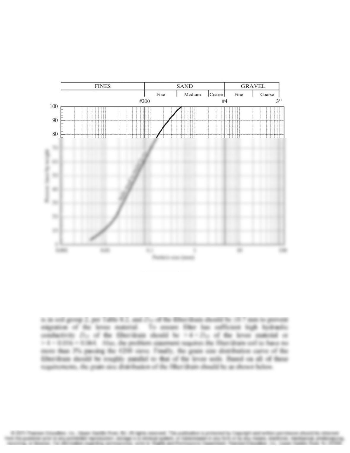
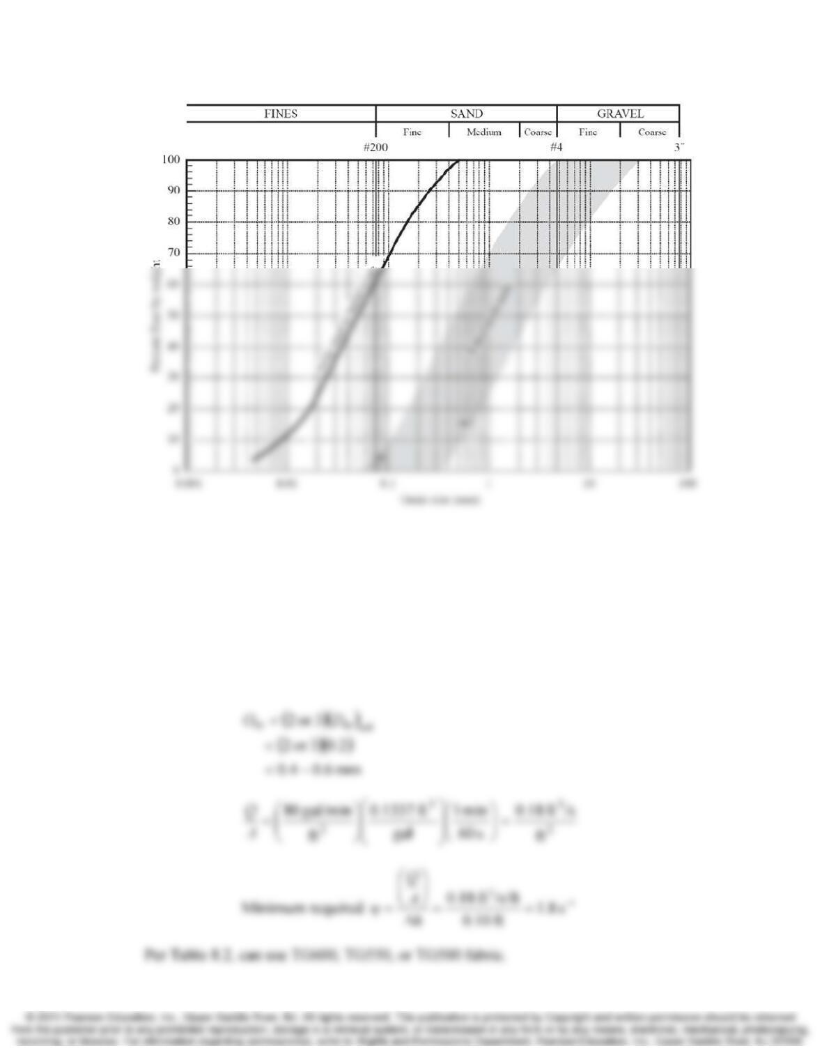
criteria described in this chapter. Determine the acceptable range of grain-size
distribution for this material and plot it on a grain-size distribution curve.
Figure 8.45 Particle size distribution of proposed levee soils for Problems 8.18 and 8.19
Solution
Per gain size distribution curve, 61% of the levee soil passes the #200 sieve. Therefore, it
Chap. 8 Groundwater—Multidimensional Flow and Applications 8-17
8.19 An alternative design for the levee in Problem 8.18 uses a perforated pipe drain instead of
the toe drain. This perforated pipe drain would be surrounded with gravel and wrapped
with a filter fabric, similar to the one shown in Figure 8.37. The design flow rate into the
drain is 80 gal/min per square foot, and the maximum acceptable head loss is 0.10 ft.
Select an appropriate fabric from Table 8.2.
Solution
Per figure 8.40, (D85)soil = 0.2 mm
8-18 Groundwater—Multidimensional Flow and Applications Chap. 8
Comprehensive
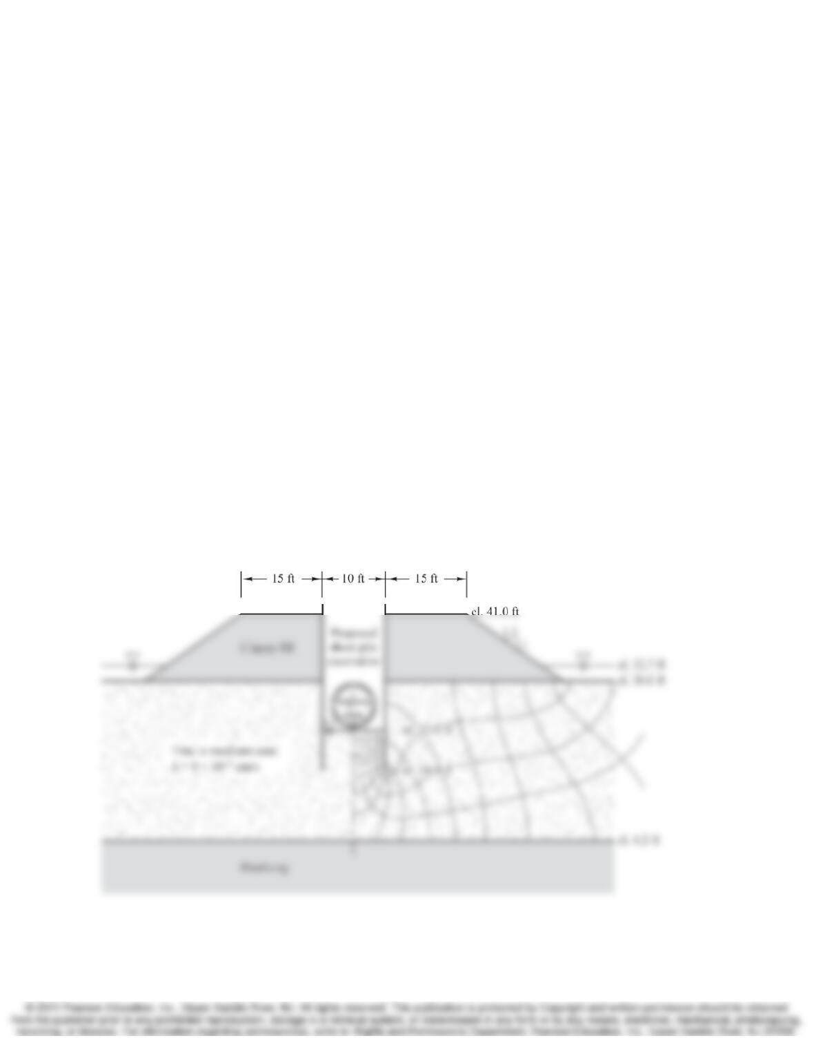
8.20 Several years ago a state highway department built a highway across a shallow lake by
placing the clayey fill shown in Figure 8.46. The top of this fill is above the high water
level, thus protecting the highway from flooding.
It is now necessary to install a buried pipeline beneath the roadway. To install this pipe,
the contractor plans to make a temporary excavation using steel sheet piles as shown.
The contractor plans to use sump pumps at 50 ft intervals to maintain the water level at
the bottom of the excavation. Once the pipe has been installed, the excavation will be
backfilled and the pumps and sheet piles removed. You are to perform the following
tasks in connection with this project:
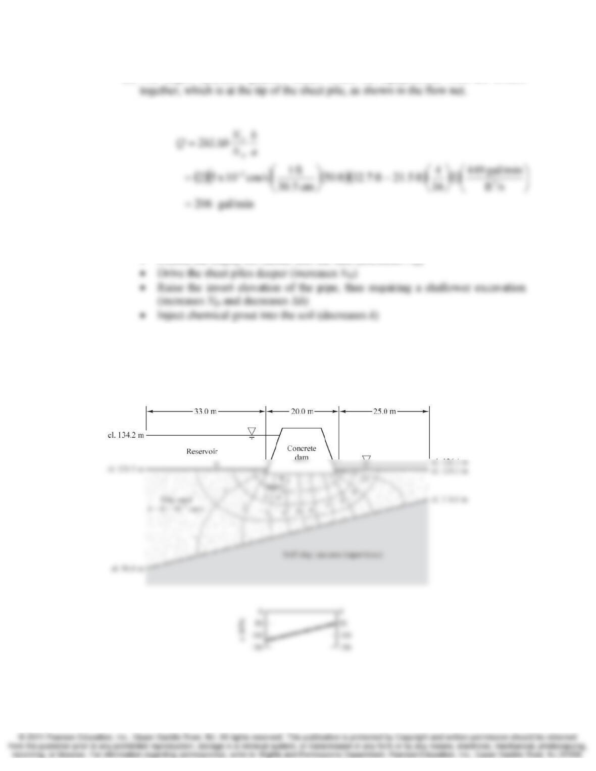
(a) Recognizing that the proposed cross-section is symmetrical, redraw half of it to a
scale of 1 in = 10 ft and construct a flow net.
(b) Determine where the largest hydraulic gradient occurs and mark this spot on the
cross-section.
(c) Using the flow net, compute the minimum required capacity for each pump,
expressed in gallons per minute.
(d) Describe two methods of reducing the flow rate into the excavation (and thus the
required pump size). Explain how each of them would reduce Q.
Solution
(a) The flow net for half of the cross-section is shown below.
Chap. 8 Groundwater—Multidimensional Flow and Applications 8-19
(b) The largest hydraulic gradient occurs where the equipotential lines are closest
(c) The flow rate is computed as
(d) The flow rate could be reduced by any of the following methods:
• Extend the clayey fill further into the lake (increases ND)
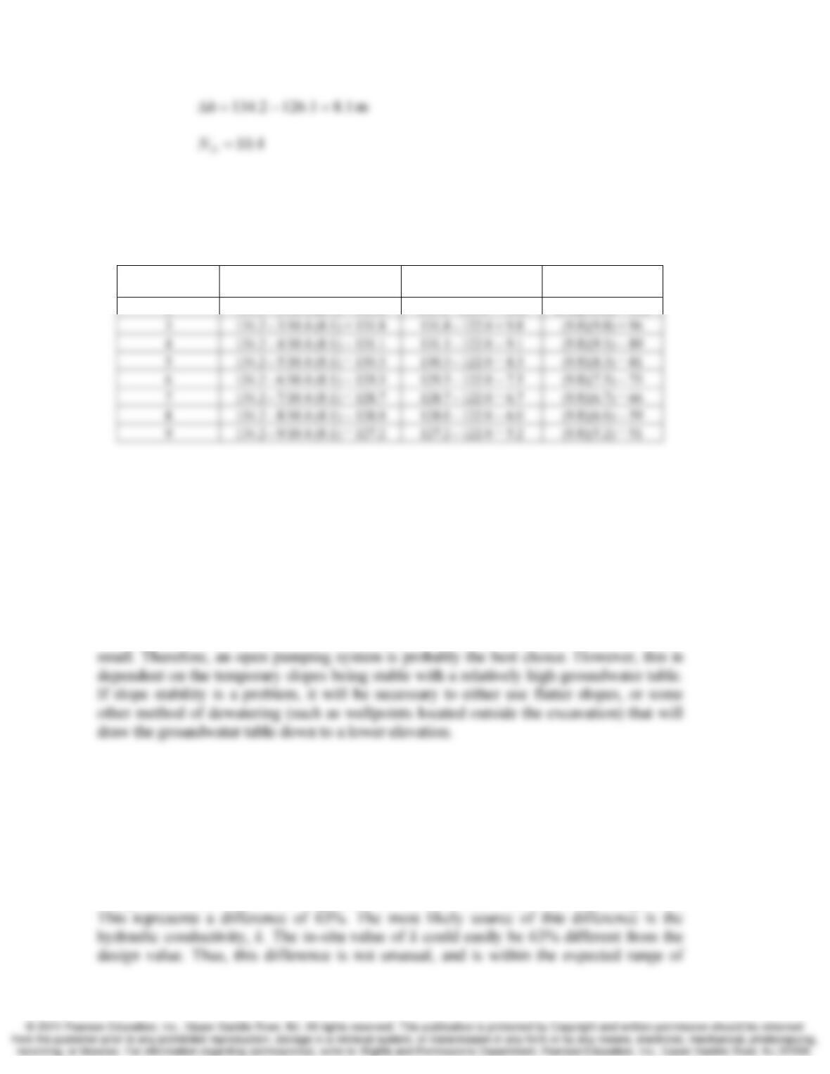
8.21 Using the flow net from Problem 8.4, compute the uplift pressures acting on the bottom
of the dam in Figure 8.39 and develop a plot similar to the one shown in Figure 8.9.
Solution
8-20 Groundwater—Multidimensional Flow and Applications Chap. 8
Compute the total head for each equipotential line based on the total head in the reservoir
and the number of equipotential drops from the reservoir to that equipontential line. Then,
use this total head to compute the pressure head and the pore water pressure along the
bottom of the dam.
Equipotential
Line Number h (m) h
p
(m) u (kPa)
2 134.2 – 2/10.4 (8.1) = 132.6 132.6 – 122.0 = 10.6 (9.8)(10.6) = 104
8.22 A 30 m wide, 40 m long, 8 m deep construction excavation needs to be made in a silty
clay (CL). The groundwater table is at a depth of 2 m. The sides of the excavation will
be sloped at an angle of about 1 horizontal to 1 vertical, and no sensitive structures or
other improvements are nearby. Suggest an appropriate method of construction
dewatering for this site, and explain the reason for your choice. Include statements of
any assumptions, if any.
Solution
The Hydraulic conductivity of CL is very low, so the Q entering the excavation will be
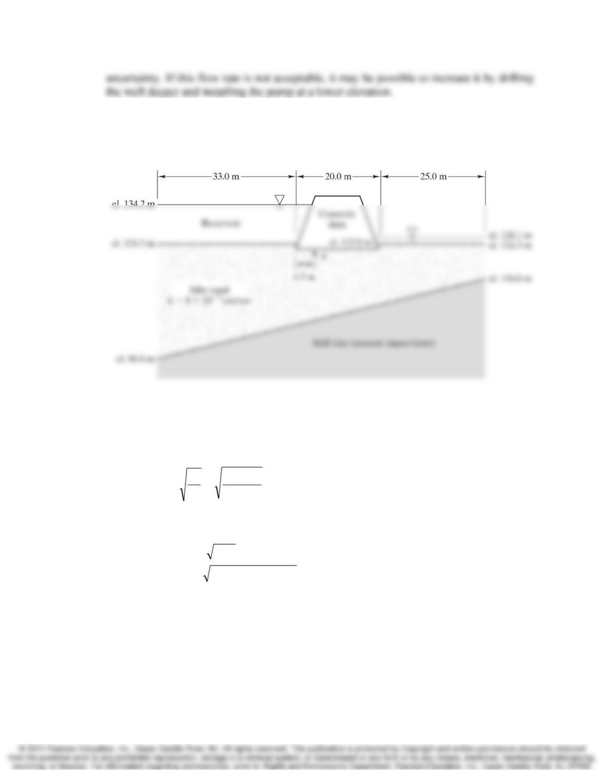
8.23 After the analysis described in Example 8.6 was completed, the well was installed to the
depth indicated in Figure 8.18. However, when the pump was installed, it produced a
flow rate of only 102 gal/min. Is the difference between this value and the computed
flow rate within the normal range of uncertainty for these kinds of analyses? Explain.
What portion of the analysis usually introduces the greatest error?
Solution
The predicted flow rate was 276 gal/min, but the actual flow rate was only 102 gal/min.
Chap. 8 Groundwater—Multidimensional Flow and Applications 8-21
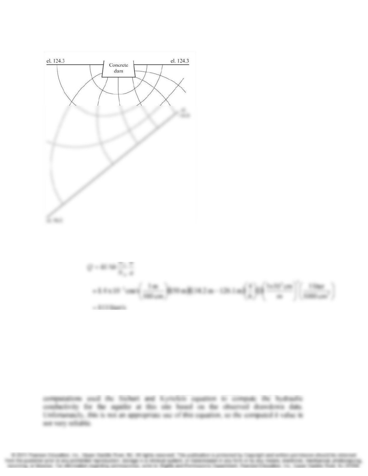
8.24 Compute Q for the cross-section in Figure 8.39 using the following hydraulic
conductivities for the silty sand: kx = 5 × 10⁻² cm/s, kz = 4 × 10⁻³ cm/s.
Solution
Figure 8.39 Cross-section of dam for Problems 8.4 and 8.5. el. = elevation.
The anisotropic soil condition requires the use of a transformed cross-section. The
vertical dimensions need to be expanded by:
3.54
10 x 4
10 x 5
3
2
== −
−
z
x
k
k
The equivalent keq used in the computations is computed as
()()
cm/s10 x 1.410 x 410 x 5 2–32 ==
=
−−
zxea kkk
8-22 Groundwater—Multidimensional Flow and Applications Chap. 8
The flow net for the transformed section is shown below.
And the flow rate is compute as
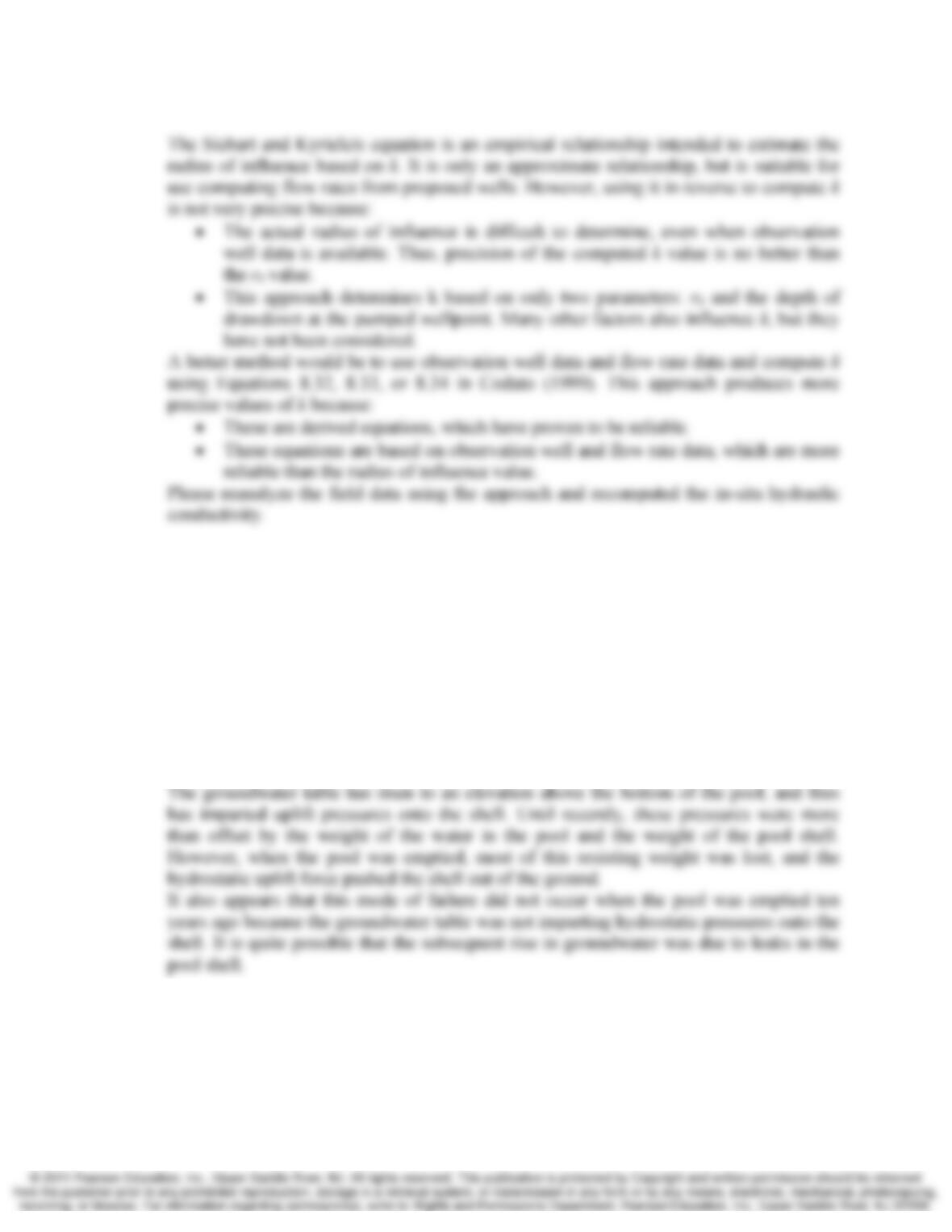
8.25 By observing the groundwater drawdown in the vicinity of a proposed well, an engineer
had determined the radius of influence, r0. This engineer then used Equation 8.34 to
compute k for the aquifer. Write a 200–300 word memo to this engineer, explaining why
this is not a good method of computing k, then suggest a better method.
Solution
MEMORANDUM
I have reviewed your computations dated _____ for the _____ well project. These
Chap. 8 Groundwater—Multidimensional Flow and Applications 8-23
8.26 A below-ground swimming pool was built twenty years ago and, until recently, has been
performing satisfactorily. About ten years ago it became necessary to temporarily drain
the pool to clean out some algae. It was then refilled without any problems. However,
the pool recently developed some cracks in its concrete shell, so it became necessary to
drain it once again. Soon after it was drained, the pool rose out of the ground a distance
of about 1 m. Provide a possible explanation for this behavior, and a possible
explanation for why the pool did not rise out of the ground when it was drained the first
time.
Solution
The recent damage to this pool appears to be the result of hydrostatic uplift pressures.
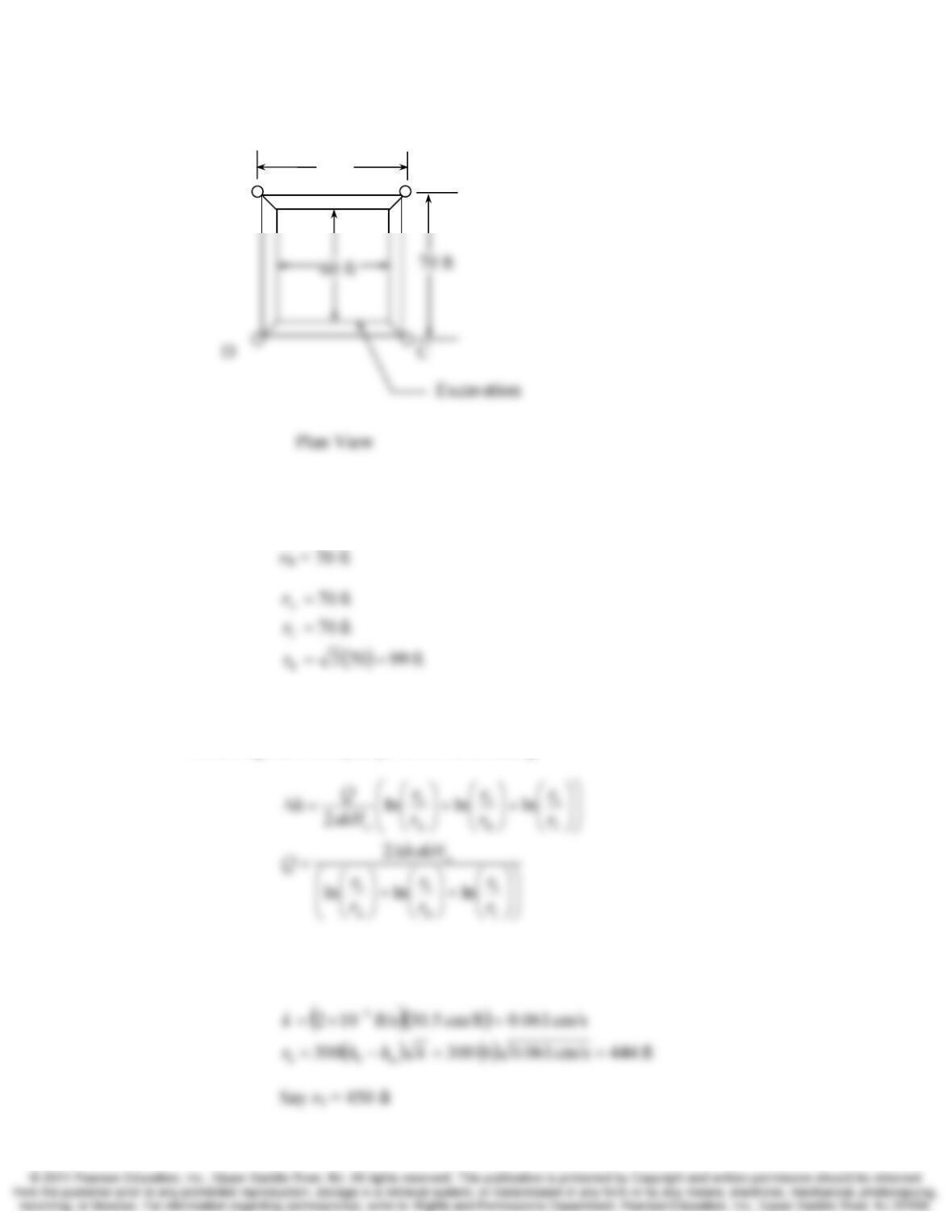
8.27 An excavation for a foundation is to be made in the upper clay soil as shown in Figure
8.47. In order to prevent the base of the excavation from being blow out by the uplift
pressure of the confined aquifer below the clay layer, the construction contractor is
planning to predrain the excavation with the well array shown. The excavation is half a
mile from a large lake that recharges the aquifer below the clay.
8-24 Groundwater—Multidimensional Flow and Applications Chap. 8
(a) Determine the depth to which the ground water table must be lowered to provide a
factor of safety of 3 against uplift of the clay layer assuming the weight of the clay is
the only resistance to uplift (i.e. ignore any strength in the clay)
(b) Assuming only three of the four wells are in operation, compute the pumping rate
required to achieve the needed drawdown.
Solution
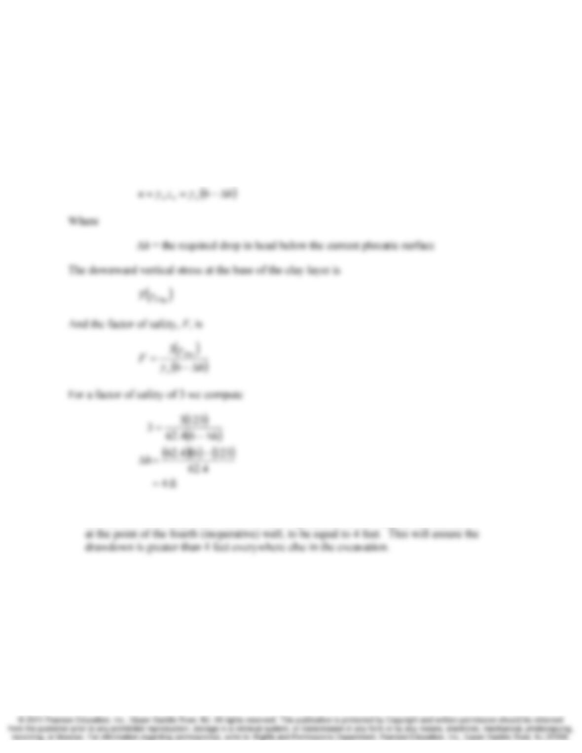
(a) The uplift pressure applied at the base of the clay is
(b) Since the spacing of wells is not close, we will use superposition to compute the
drawdown. Since only three wells will be in operation, we will require the drawdown
Chap. 8 Groundwater—Multidimensional Flow and Applications 8-25
Assume Well D is the inoperative well. The radius from each well to Well D is
rA = 70 ft
The aquifer is confined so Equation 8.32 applies and, using superposition, the
drawdown from all three wells will be the sum of the drawdown from each well.
Assuming each well pumps at the same rate, Q
We have no information about a recharge source so we must estimate r0 using
Equation 8.34. Assume the drawdown at the wells is equal to 6 feet
70 ft
A B

8-26 Groundwater—Multidimensional Flow and Applications Chap. 8
each wellfor gal/min 85
lnlnln
2
C
0
B
0
A
0
=
⎟
⎟
⎞
⎜
⎜
⎛
⎟
⎟
⎠
⎞
⎜
⎜
⎝
⎛
+
⎟
⎟
⎠
⎞
⎜
⎜
⎝
⎛
+
⎟
⎟
⎠
⎞
⎜
⎜
⎝
⎛
Δ
=
π
r
r
r
r
r
r
kHh
Qa