PROBLEM 8.49
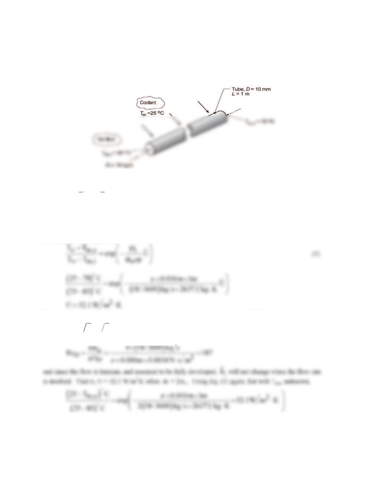
KNOWN: Hot fluid passing through a thin-walled tube with coolant in cross flow over the tube. Fluid
flow rate and inlet and outlet temperatures.
FIND: Outlet temperature, Tm,o , if the flow rate is increased by a factor of 2 with all other conditions the
same.
SCHEMATIC:
ASSUMPTIONS: (1) Steady-state conditions, (2)Hot fluid is incompressible with negligible viscous
dissipation, (3) Constant properties, (4) Fully developed flow and thermal conditions, (5) Convection
coefficients,
oi
h and h
, independent of temperature, and (6) Negligible wall thermal resistance.
PROPERTIES: Hot fluid (Given): ρ = 1079 kg/m3, cp = 2637 J/kg⋅K, m = 0.0034 N⋅s/m2, k = 0.261
W/m⋅K.
ANALYSIS: For conditions prescribed in the Schematic, Eq 8.45a can be used to evaluate the overall
convection coefficient with P = πD,
The overall coefficient can be expressed in terms of the inside and outside coefficients,
( )
1
io
U 1h 1h −
= +
(2)
Characterize the internal flow with the Reynolds number, Eq. 8.6,
m,o
T 81.4 C=
<
COMMENTS: Examine the assumptions and explain why they were necessary in order to affect the
solution.

PROBLEM 8.50
KNOWN: Thin walled tube of prescribed diameter and length. Water inlet temperature and flow rate.
FIND: (a) Outlet temperature of the water when the tube surface is maintained at a uniform temperature
Ts = 27°C assuming
m
T
= 300 K for evaluating water properties, (b) Outlet temperature of the water
when the tube is heated by cross flow of air with V = 10 m/s and
T
∞
= 100°C assuming
f
T
= 350 K for
evaluating air properties, and (c) Outlet temperature of the water for the conditions of part (b) using
properly evaluated properties.
SCHEMATIC:
ASSUMPTIONS: (1) Steady-state conditions, (2) Incompressible liquid with negligible viscous
dissipation and negligible axial conduction, (3) Fully developed flow and thermal conditions for internal
flow, and (4) Negligible tube wall thermal resistance.
PROPERTIES: Table A.6, Water (
T
= 300 K): ρ = 997 kg/m3, cp = 4179 J/kg⋅K, m = 855 × 10-6
ANALYSIS: (a) For the constant wall temperature cooling process, Ts = 27°C, the water outlet
temperature can be determined from Eq. 8.41b, with P = πD,
To estimate the convection coefficient, characterize the flow evaluating properties at
m
T
= 300 K
Hence, the flow is turbulent and assuming fully developed (L/D = 200), and using the Dittus–Boelter
i
h
k
0.010 m
Substituting this value for
i
h
into Eq. (1), find
( )
(b) For the air heating process,
T
∞
= 100°C, the water outlet temperature follows from Eq. 8.45a,
Continued…
m
f
T
PROBLEM 8.50 (Cont.)
where the overall coefficient is
( )
io
U 1h 1h= +
(4)
To estimate
o
h
, use the Churchill-Bernstein correlation, Eq. 7.54, for cross flow over a cylinder using
properties evaluated at
f
T
= 350 K.
The value of
i
h
can be recalculated for heating conditions:
0.8 0.4
i
DD
hD
Nu 0.023Re Pr
k
= =
( ) ( )
0.8 0.4 2
i
0.613W m K
h 0.023 29,783 5.83 10,800 W m K
0.010 m
⋅
= = ⋅
Next, find
U
then Tm,o,
(c) Using the IHT Correlation Tools for Internal Flow (Turbulent Flow) and External Flow (over a
Cylinder) the analyses of part (b) were performed considering the appropriate temperatures to evaluate
the thermophysical properties. For internal and external flow, respectively,
where the average tube wall temperature is evaluated from the thermal circuit,
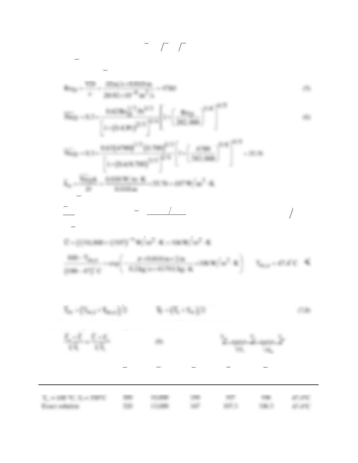
The results of the analyses are summarized in the table along with the results from parts (a) and (b),
Condition
m
T
i
h
f
T
o
h
U
T
m,o
(K)
(W/m2⋅K)
(K)
(W/m2⋅K)
(W/m2⋅K)
(°C)
Ts = 27°C
300
9080
—
–—
—
37.1°C
Continued…

PROBLEM 8.50 (Cont.)
PROBLEM 8.51
KNOWN: Water flow rate and inlet temperature for a thin-walled tube of prescribed length
and diameter.
FIND: Water outlet temperature for each of the following conditions: (a) Tube surface
maintained at 27°C, (b) Insulation applied and outer surface maintained at 27°C, (c) Insulation
applied and outer surface exposed to ambient air at 27°C.
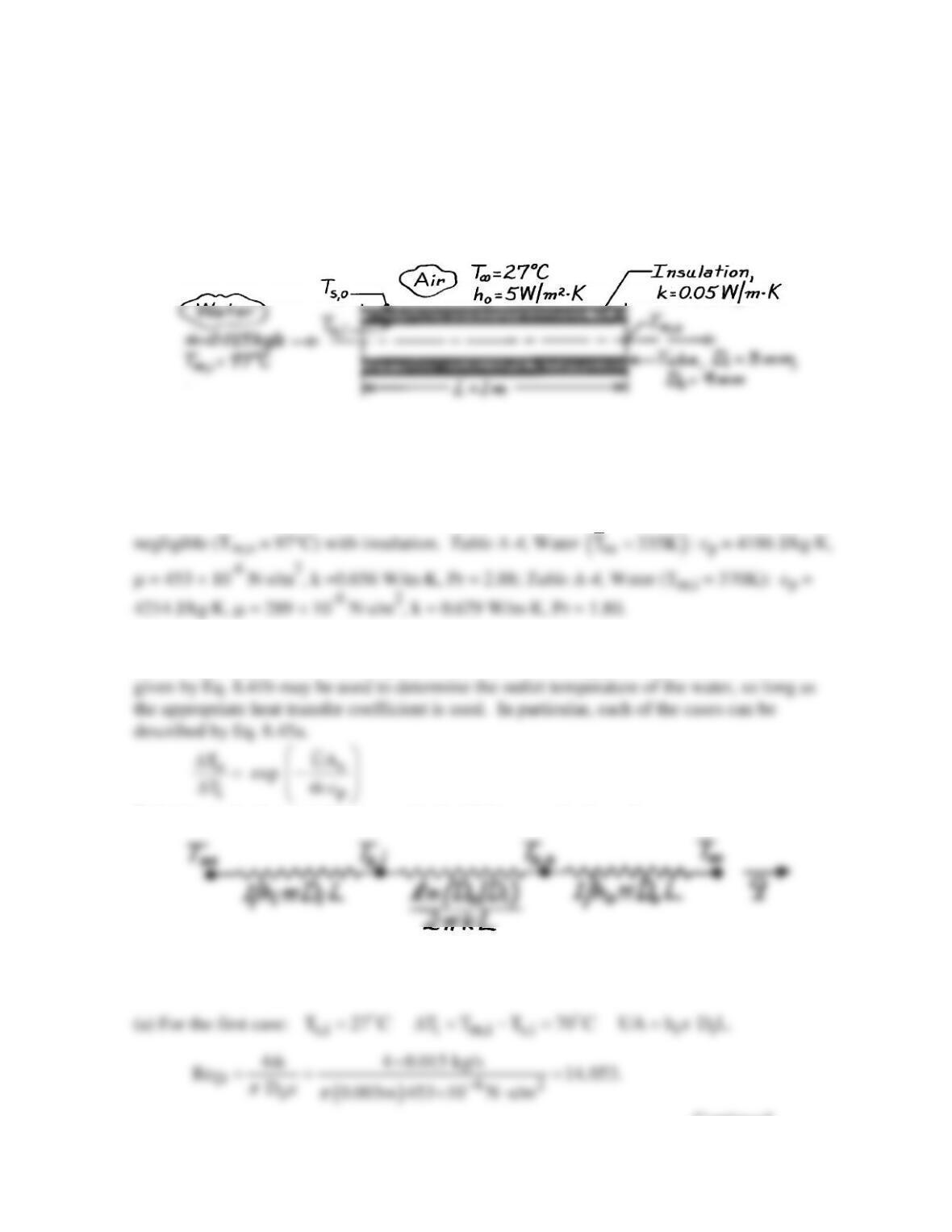
SCHEMATIC:
ASSUMPTIONS: (1) Steady-state conditions, (2) Fully developed flow throughout the tube,
(3) Negligible tube wall conduction resistance, (4) Negligible contact resistance between tube
wall and insulation, (5) Uniform outside convection coefficient.
PROPERTIES: Assume water cools to Tm,o = 27°C with no insulation but that cooling is
ANALYSIS: For each of the three cases, heat is transferred from the warm water to a surface
(or the air) which is at a fixed temperature (27°C). Accordingly, an expression of the form
Referring to the thermal circuit associated with heat transfer from the water,
and the UA product may be evaluated as
( )
1
t
UA R .
−
= Σ
Continued …
PROBLEM 8.51 (Cont.)
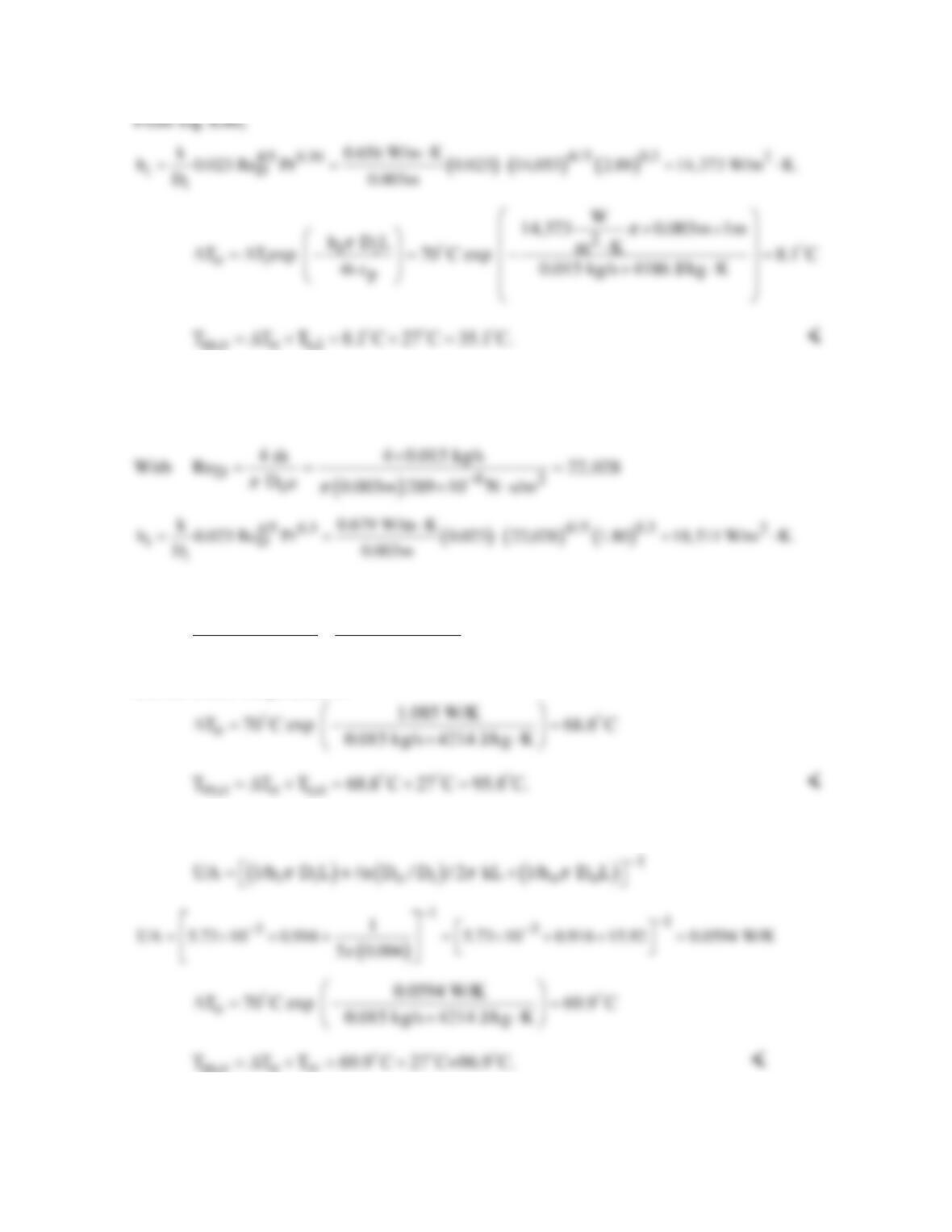
(b) For the second case: Ts,o = 27°C with
( ) ( )
1
i m,i s,o i i o i
T T T 70 C UA 1/h D L n D / D / 2 kL .
ππ
−
∆= − = = +
It follows that
( )
( )
11
3
n 0.004/0.003
1
UA 5.73 10 0.916 1.085 W/K
18,511 0.003 2 0.05
ππ
−−
−
= + = ×+ =
×
and the outlet temperature is
(c) For the third case: T∞ = 27°C, ∆Ti = Tm,i – T∞ = 70°C and
m,o o
∞
COMMENTS: Note that Rconv,o >> Rcond,insul >> Rconv,i.
PROBLEM 8.52
KNOWN: Dimensions of circular tube, applied constant heat flux, inlet temperature, mass flow rate,
and expression for nanofluid viscosity.
FIND: Tube wall temperature at the tube exit for pure water and for a water-Al2O3 nanofluid.
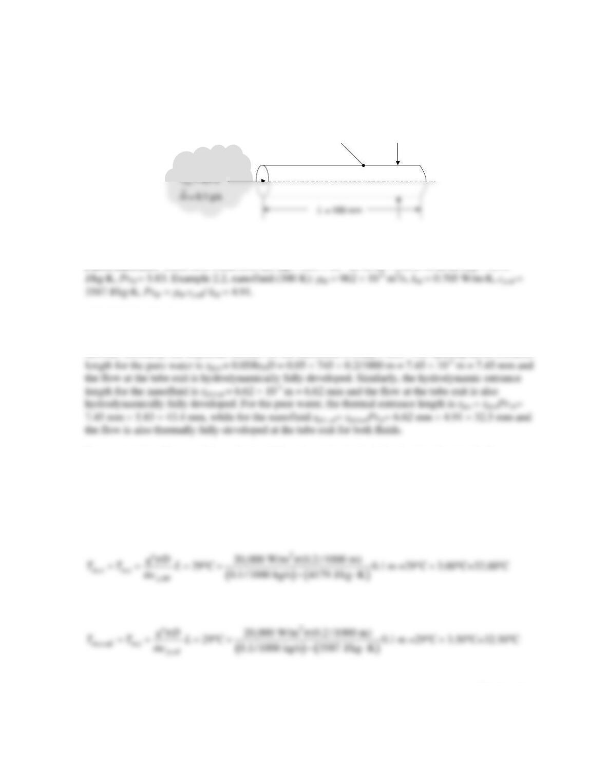
SCHEMATIC:
ASSUMPTIONS: (1) Constant properties.
PROPERTIES: Table A.4, water (300 K):
m
ANALYSIS: The Reynolds number for the pure water
is
(
)
62
bf
4 / 4 (0.1/1000 kg/s) / 0.0002 m 855 10 N s/m 745
D
Re m D
πm π
−
==× ×××⋅=
and the flow is
laminar. Similarly, the Reynolds number for the nanofluid is ReD,nf = 662. The hydrodynamic entrance
For constant heat flux conditions, the local Nusselt number in the fully-developed region is NuD =
4.36. Therefore, the local heat transfer coefficient at the tube exit is:
Pure fluid: hbf = NuDkbf/D = 4.36 × 0.613 W/m⋅K /(0.2/1000m) = = 13,360 W/m2⋅K.
Nanofluid: hnf = NuDknf/D = 4.36 × 0.705 W/m⋅K /(0.2/1000m) = = 15,370 W/m2⋅K.
Applying Eq. (8.40) to the pure fluid yields
whereas applying Eq. (8.40) to the nanofluid results in
Continued…
q
= 20 kW/m
2
D = 0.2 mm
H
2
O or H
2
O-Al
2
O
3
H
2
O or H
2
O-Al
2
O
3
PROBLEM 8.52 (Cont.)
From Eq. (8.27) the wall temperature at the outlet of the tube carrying the pure water is,
COMMENTS: Although the nanofluid provides a larger thermal conductivity and, in turn, a larger
convective heat transfer coefficient relative to the pure water, the wall temperature at the tube outlet
with the nanofluid exceeds that of the wall temperature using pure water. This is due to the reduction
PROBLEM 8.53
KNOWN: Dimensions of circular tube, applied constant heat flux, inlet temperature, mass flow rate.
FIND: Tube wall temperature at the tube exit for pure water and for a water-Al2O3 nanofluid.
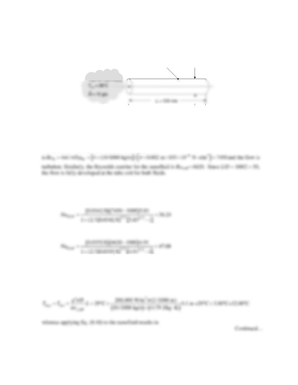
SCHEMATIC:
ASSUMPTIONS: (1) Constant properties.
PROPERTIES: Table A.4, water (300 K):
m
bf = 855 × 10-6 m2/s, kbf = 0.613 W/m⋅K, cp,bf = 4179
J/kg⋅K, Prbf = 5.83. Example 2.2, nanofluid (300 K):
m
nf = 962 × 10-6 m2/s, knf = 0.705 W/m⋅K, cp,nf =
3587 J/kg⋅K, Prnf = 4.91.
ANALYSIS: The Reynolds number for the pure water
The local Nusselt number is evaluated using the Gnielinski correlation. For pure water, Eq. (8.21)
yields, fbf = (0.790ln(7450) – 1.64)-2 = 0.0342 while for the nanofluid, fnf = (0.790ln(6620) – 1.64)-2 =
0.0355. The Gnielinski correlation yields, for the pure fluid
while for the nanofluid,
()
Hence, hbf = NuD,bfkbf/D = 56.24(0.613 W/m⋅K)/0.002 m = 17,240 W/m2⋅K and hnf = NuD,bfknf/D =
47.08(0.705 W/m⋅K)/0.002 m = 16,600 W/m2⋅K.
Applying Eq. (8.40) to the pure fluid yields
q
= 200 kW/m
2
D = 2 mm
PROBLEM 8.53 (Cont.)
()()
2
,,nf ,
,nf
200,000 W/m (2 / 1000 m)
29 C 0.1 m =29 C 3.50 C=32.50 C
10 / 1000 kg/s 3587 J/kg K
mo mi
p
qD
TT L
mc
ππ
′′
=+ =°+ °+° °
×⋅
From Eq. (8.27) the wall temperature at the outlet of the tube carrying the pure water is,
,bf
() /
smo
Tx L T q h
′′
== +
COMMENT: The nanofluid provides a larger thermal conductivity but a smaller convective heat
transfer coefficient relative to the pure water. If the objective is to minimize the wall temperature at
PROBLEM 8.54
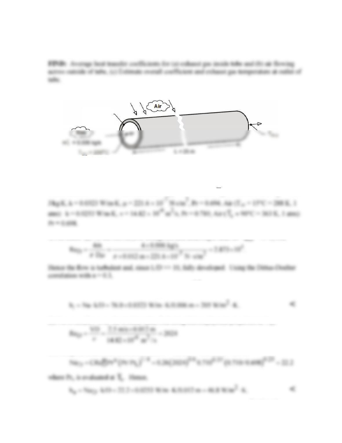
KNOWN: Exhaust gases at 200°C and mass rate 0.006 kg/s enter tube of diameter 12 mm
and length 25 m. Tube experiences cross-flow of autumn winds at 15°C and 5 m/s.
SCHEMATIC:
ASSUMPTIONS: (1) Steady-state conditions, (2) Ideal gas with negligible viscous
dissipation and pressure variation, (3) Negligible tube wall resistance, (4) Exhaust gas
properties are those of air, (5) Negligible radiation effects.
PROPERTIES: Table A-4, Air (assume Tm,o ≈ 15°C, hence T
m
= 380 K, 1 atm): cp = 1012
ANALYSIS: (a) For the internal flow through the tube assuming a value for Tm,o = 15°C, find
()
( )
0.8 0.3
0.8 0.3 4
DD
Nu 0.023Re Pr 0.023 2.873 10 0.694 76.0==×=
(b) For cross–flow over the circular tube, find using thermophysical properties at T∞,
and using the Zukauskus correlation with C = 0.26, m = 0.6, and n = 0.37,
Continued …
66
T
∞
= 15°C
V = 2.5 m/s
Tube
D = 12 mm
PROBLEM 8.54 (Cont.)
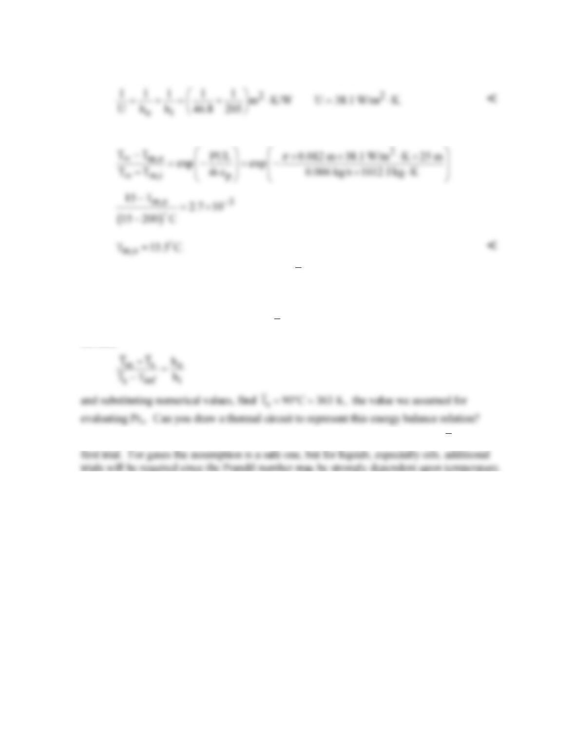
(c) Assuming the thermal resistance of the tube wall is negligible,
The gas outlet temperature can be determined from the expression where P = πD.
COMMENTS: (1) With Tm,o = 15.5°C, find
m
T
= 381 K; hence thermophysical properties
for the internal flow correlation were evaluated at a reasonable temperature. Note that the gas
is cooled from 200°C to near ambient air temperature, Tm,o ≈ T∞, over the 25 m length.
(2) The average wall surface temperature,
s
T,
follows from an energy balance on the wall
surface,
s
(3) When using the Zukauskus correlation, it is reasonable to evaluate Prs at the
m
T
for the
L=16m
PROBLEM 8.55
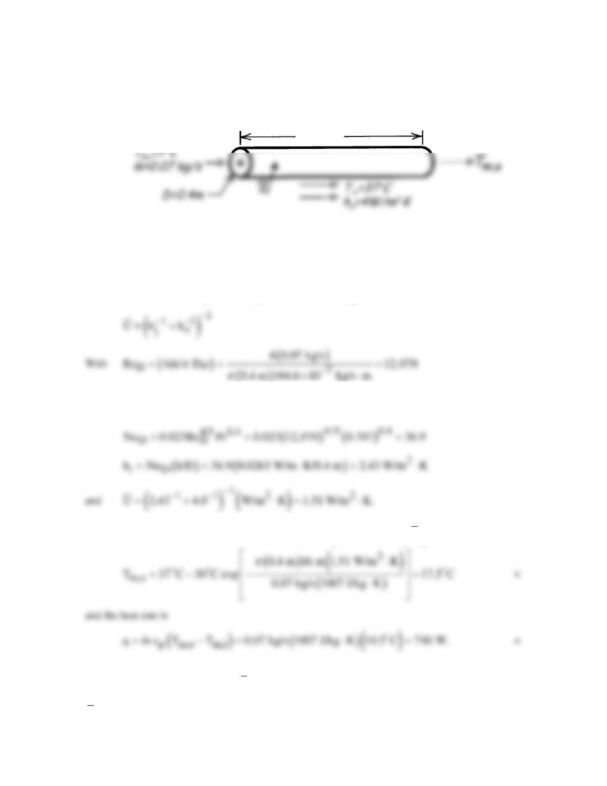
KNOWN: Length and diameter of air conditioning duct. Inlet temperature of chilled air.
Temperature and convection coefficient associated with outer air. Chilled air flowrate.
FIND: Chilled air exit temperature and heat flow rate.
SCHEMATIC:
ASSUMPTIONS: (1) Steady-state conditions, (2) Negligible tube wall conduction resistance, (3)
Ideal gas with negligible viscous dissipation, pressure variation, and axial conduction.
PROPERTIES: Table A-4, Air (300 K, 1 atm): cp = 1007 J/kg⋅K, m = 184.6 × 10⁻⁷ kg/s⋅m, k =
0.0263 W/m⋅K, Pr = 0.707.
ANALYSIS: The exit temperature may be obtained from Eq. 8.45a, where
the flow is turbulent and, assuming fully developed conditions over the entire length, the Dittus–
Boelter correlation yields
Eq. 8.45a yields
( )
( )
m,o m,i p
T T T T exp DL/m c U
π
∞∞
=−− −
COMMENTS: (1) The temperature rise of the chilled air is excessive, and the outer surface of the
duct should be insulated to reduce
U
and thereby Tm,o and q. (2) The temperature selected for
evaluating air properties was not very accurate. Air properties should be evaluated at
m m,o m,i
T (T T ) / 2 285 K=+≈
.
PROBLEM 8.56
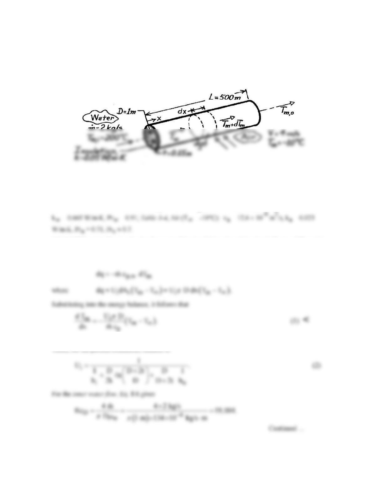
KNOWN: Flow conditions associated with water passing through a pipe and air flowing over the
pipe.
FIND: (a) Differential equation which determines the variation of the mixed–mean temperature of the
water, (b) Heat transfer rate per unit length of pipe at the inlet and outlet temperature of the water.
SCHEMATIC:
ASSUMPTIONS: (1) Negligible temperature drop across the pipe wall, (2) Negligible radiation
exchange between outer surface of insulation and surroundings, (3) Fully developed flow throughout
pipe, (4) Water is incompressible liquid with negligible viscous dissipation.
PROPERTIES: Table A-6, Water (Tm,i = 200°C): cp,w = 4500 J/kg⋅K, mw = 134 × 10-6 N⋅s/m2,
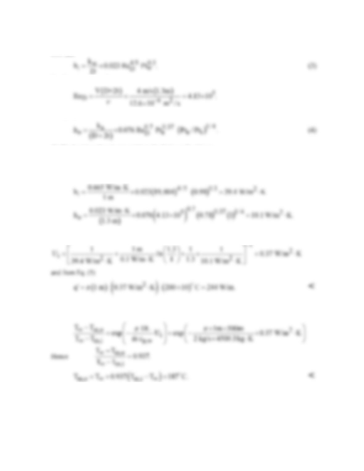
ANALYSIS: (a) Following the development of Section 8.3.1 and applying Eq. 1.12e to a differential
element in the water, we obtain
The overall heat transfer coefficient based on the inside surface area may be evaluated from Eq. 3.36
which, for the present conditions, reduces to
PROBLEM 8.56 (Cont.)
Hence, the flow is turbulent. With the assumption of fully developed conditions, it follows from Eq.
8.60 that
For the external air flow
Using Eq. 7.53 to obtain the outside convection coefficient,
(b) The heat transfer rate per unit length of pipe at the inlet is
( )
i m,i
q D U T T .
π
∞
′= −
(5)
From Eqs. (3 and 4),
Hence, from Eq. (2)
Since Ui is a constant, independent of x, Eq. (1) may be integrated from x = 0 to x = L. The result is
Eq. 8.45a.
COMMENTS: The largest contribution to the denominator on the right-hand side of Eq. (2) is made
by the conduction term (the insulation provides 96% of the total resistance to heat transfer). For this
reason the assumption of fully developed conditions throughout the pipe has a negligible effect on the
calculations. Since the reduction in Tm is small (13°C), little error is incurred by evaluating all
properties of water at Tm,i.
PROBLEM 8.57
KNOWN: Inner and outer radii and thermal conductivity of a Teflon tube. Flowrate and temperature
of confined water. Heat flux at outer surface and temperature and convection coefficient of ambient
air.
FIND: Fraction of heat transfer to water
and temperature of tube outer surface.
SCHEMATIC:
ASSUMPTIONS: (1) Steady-state conditions, (2) Fully-developed flow, (3) One-dimensional
conduction, (4) Negligible tape contact and conduction resistances.
PROPERTIES: Table A-6, Water (Tm = 290K): m = 1080 × 10-6 kg/s⋅m, k = 0.598 W/m⋅K, Pr =
7.56.
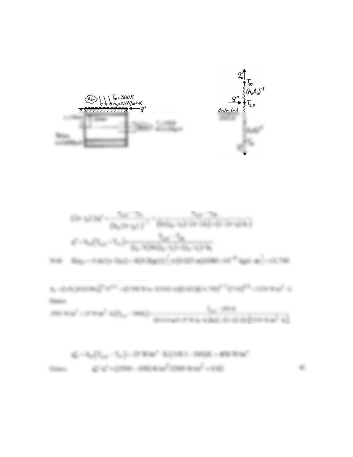
ANALYSIS: The outer surface temperature follows from a surface energy balance
the flow is turbulent and Eq. 8.60 yields
and solving for Ts,o, Ts,o = 318.3 K. <
The heat flux to the air is
COMMENTS: The resistance to heat transfer by convection to the air substantially exceeds that due
to conduction in the teflon and convection in the water. Hence, most of the heat is transferred to the
water.
=2500W/m
2
PROBLEM 8.58
KNOWN: Temperature recorded by a thermocouple inserted in a stack containing flue gases with a
prescribed flow rate. Diameters and emissivities of thermocouple tube and gas stack. Conditions
associated with stack surroundings.
FIND: Equations for predicting thermocouple error and error associated with prescribed conditions.
SCHEMATIC:
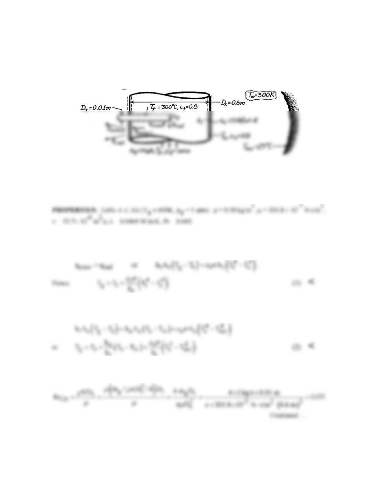
ASSUMPTIONS: (1) Steady-state conditions, (2) Flue gas has properties of air at Tg ≈ 327°C, (3)
Stack forms a large enclosure about the thermocouple tube and surroundings form a large enclosure
around the stack, (4) Stack surface energy balance is unaffected by heat loss to tube, (5) Gas flow is
fully developed, (6) Negligible conduction along thermocouple tube, (7) Stack wall is thin.
ANALYSIS: Determination of the thermocouple error necessitates determining the gas temperature
Tg and relating it to the thermocouple temperature Tt. From an energy balance applied to a control
surface about the thermocouple,
t
However, Ts is unknown and must be determined from an energy balance on the stack wall.
conv,i conv,o rad
qqq= +
ii
Tg and Ts may be determined by simultaneously solving Eqs. (1) and (2). For the prescribed
conditions
PROBLEM 8.58 (Cont.)
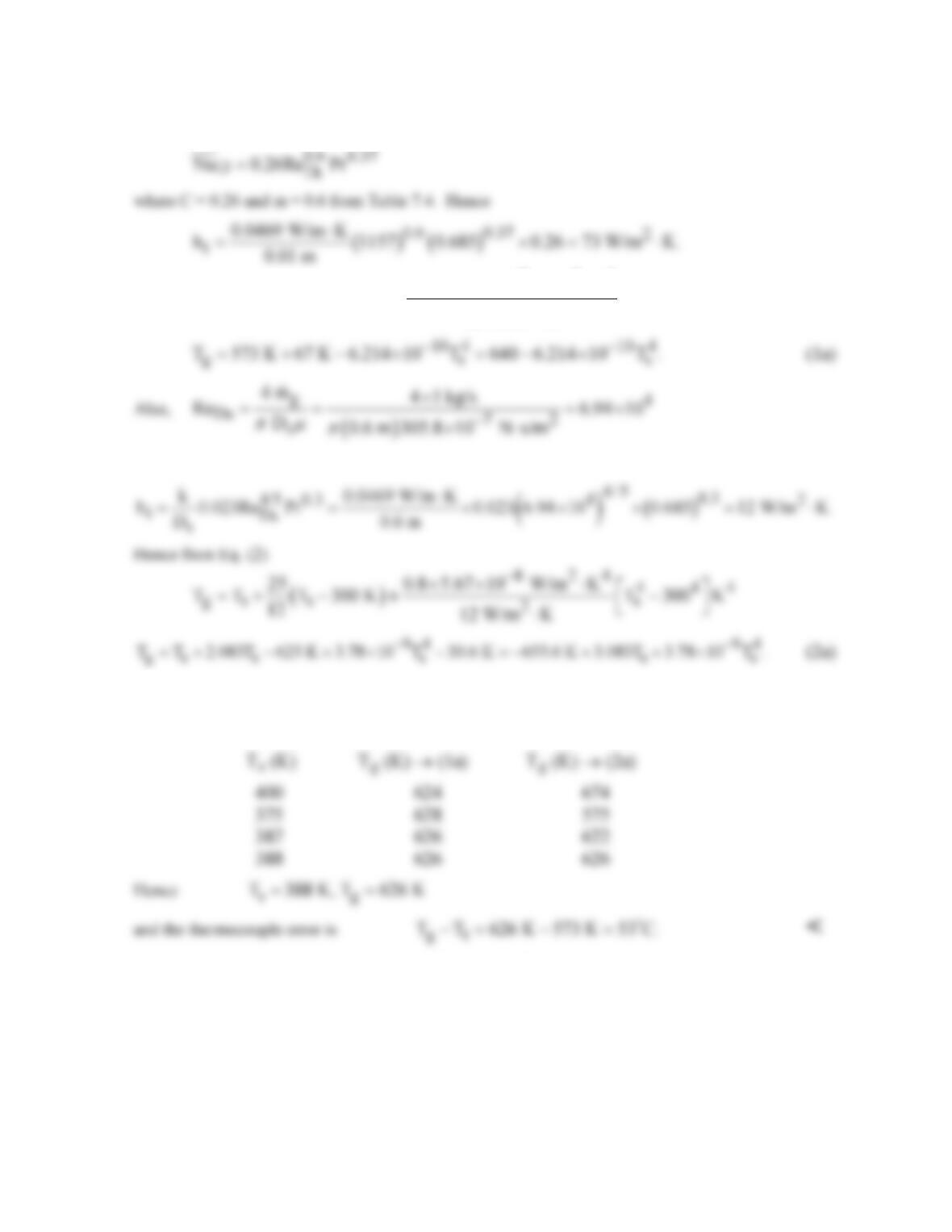
Assuming (Pr/Prs) = 1, it follows from the Zukauskus correlation
Hence, from Eq. (1)
()
8 24 4 44
gs
2
0.8 5.67 10 W/m K
T 573 K 573 T K
73 W/m K
−
×× ⋅
=+−
⋅
and the gas flow is turbulent. Hence from the Dittus-Boelter correlation,
Solve Eqs. (1a) and (2a) by trial-and-error. Assume values for Ts and determine Tg from (1a) and
(2a). Continue until values of Tg agree.
COMMENTS: The thermocouple error results from radiation exchange between the thermocouple
tube and the cooler stack wall. Anything done to ↑ Ts would ↓ this error (e.g., ↓ ho or ↑ T∞ and
Tsur). The error also ↓ with ↑ ht. The error could be reduced by installing a radiation shield around
the tube.
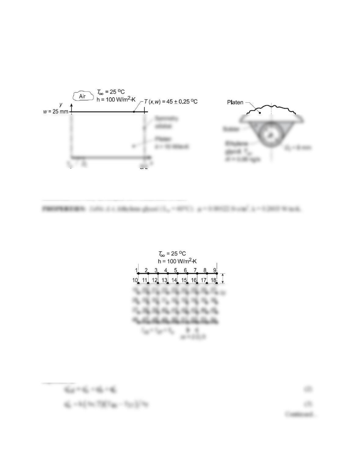
PROBLEM 8.59
KNOWN: Platen heated by hot ethylene glycol flowing through tubing arrangement with spacing S
soldered to lower surface. Top surface exposed to convection process.
FIND: Tube spacing S and heating fluid temperature Tm which will maintain the top surface at 45 ±
0.25°C.
SCHEMATIC:
ASSUMPTIONS: (1) Steady-state conditions; (2) Lower surface is insulated, all heat transfer from hot
fluid is into platen; (3) Copper tube is thick-walled such that interface between solder and platen is
isothermal; (4) Fully developed flow conditions in tube.
ANALYSIS: Begin the analysis by setting up a nodal mesh (9 ×6) to represent the platen experiencing
convection on the top surface (
T∞
, h) while the two side boundaries are symmetry adiabats. On the lower
surface, nodes 46 and 47 represent the isothermal platen-solder interface maintained at To by the hot
fluid. The remaining nodes (49-54) are insulated on their lower boundary.
The heat rate supplied by the tube to the platen can be expressed as
( )( )
cv o i m o
q 0.5h D T T
π
′= −
(1)
From energy balances about nodes 46 and 47, the heat rate into the platen by conduction can be
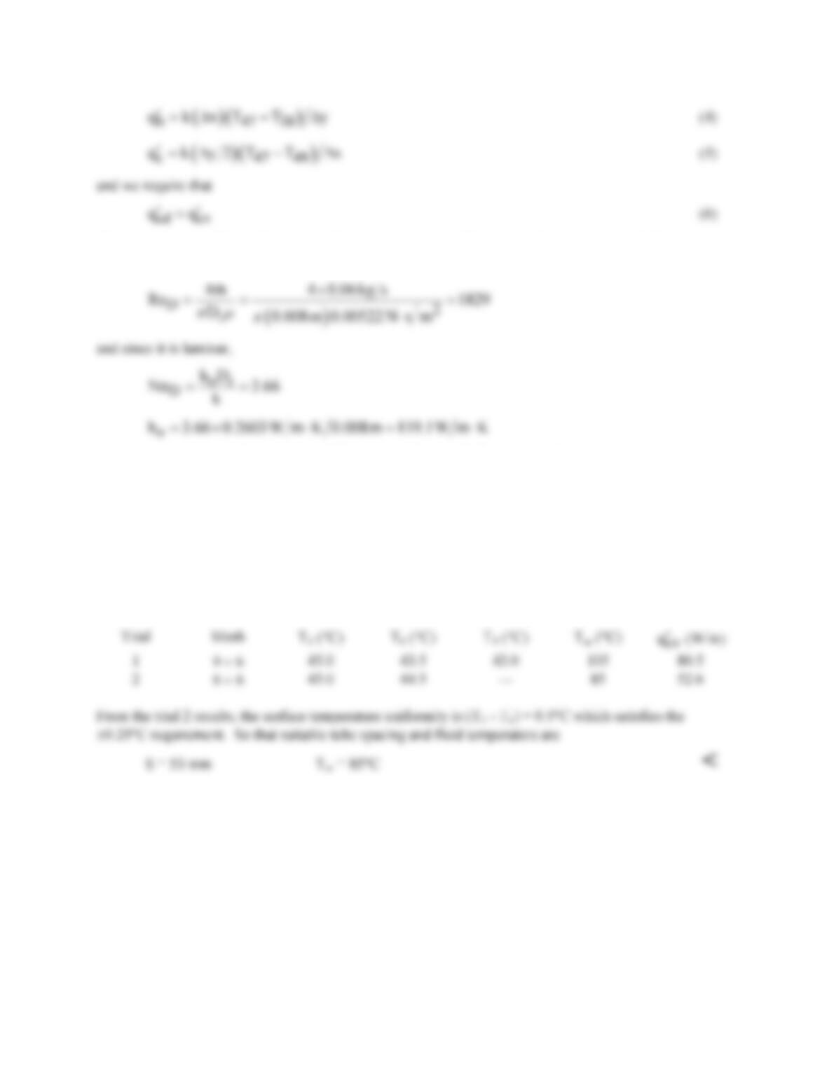
PROBLEM 8.59 (Cont.)
The convection coefficient for internal flow can be estimated from a correlation assuming fully
developed flow. First, characterize the flow with
where properties are evaluated at Tm. Using the IHT Finite–Difference Tool for Two-Dimensional
Steady-State Conditions and the Properties Tool for Ethylene Glycol, along with the foregoing rate
equations and energy balances, Eqs. (1-6), a model was developed to solve for the temperature
distribution in the platen. In the solution, we determined what hot fluid temperature was required to
maintain T1 = 45°C. Two trials were run. In the first, the nodal arrangement was as shown above (9 × 6)
for which S/2 = (9 – 1)∆x = 42.67 mm with ∆x = 2Di/3 = 5.33 mm and ∆y = w/5 = 5 mm. In the second
trial, we repositioned the right-hand symmetry adiabat to pass vertically through the nodes 6-51 so that
now the nodal mesh is (6 × 6) and S/2 = (6 – 1)∆x = 26.65 mm with ∆x and ∆y remaining the same. The
results of the trials are tabulated below.
COMMENTS: (1) Recognize that the grid spacing is quite coarse and good practice demands that we
repeat the analysis decreasing the nodal spacing until no further changes are seen in Tm.
(2) In the first trial, note that Tm = 105°C which of course, is not possible.