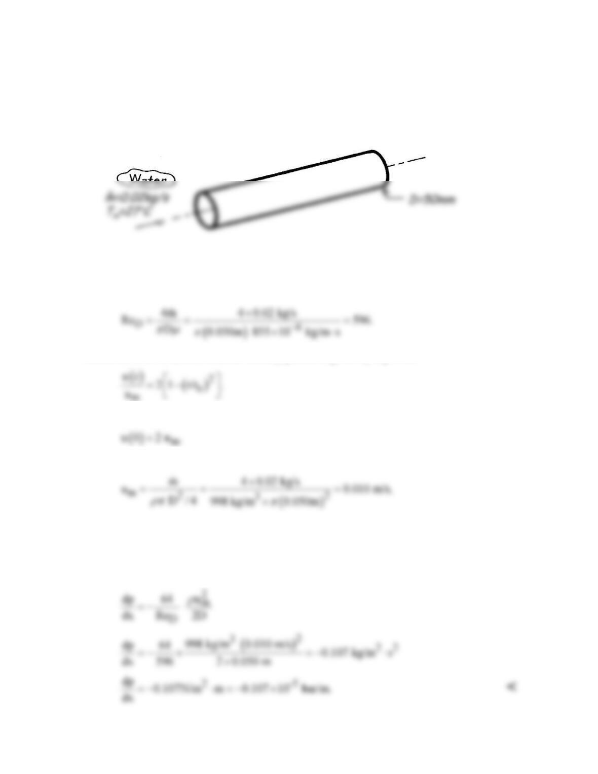
PROBLEM 8.1
KNOWN: Flowrate and temperature of water in fully developed flow through a tube of
prescribed diameter.
FIND: Maximum velocity and pressure gradient.
SCHEMATIC:
ASSUMPTIONS: (1) Steady–state conditions, (2) Isothermal flow, (3) Horizontal tube.
PROPERTIES: Table A-6, Water (300 K): ρ = 998 kg/m3, m = 855 × 10-6 N⋅s/m2.
ANALYSIS: From Eq. 8.6,
Hence the flow is laminar and the velocity profile is given by Eq. 8.15,
The maximum velocity is therefore at r = 0, the centerline, where
From Eq. 8.5
hence
( )
u 0 0.020 m/s.=
<
Combining Eqs. 8.16 and 8.19, the pressure gradient is
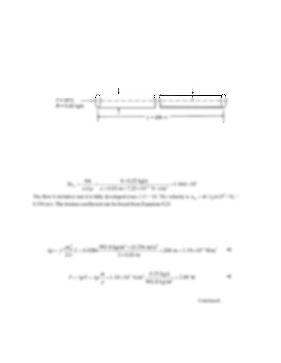
PROBLEM 8.2
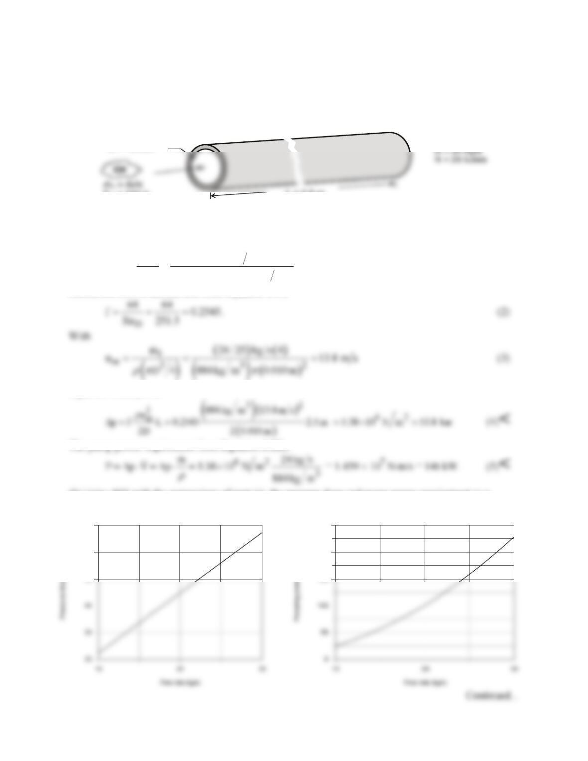
KNOWN: Mass flow rate and inlet temperature of water flowing in horizontal tube. Length and diameter
of tube. Thickness and roughness of scale on tube inner surface (fouled conditions).
FIND: Pressure drop from tube inlet to exit and pumping power for clean and fouled conditions.
SCHEMATIC:
Clean
D= 30 mm
Water
Fouled
Scale,
thickness t= 2 mm
roughness e= 0.2 mm
ASSUMPTIONS: (1) Steady-state conditions, (2) Isothermal flow, (3) Uniform properties, (4)
Fully developed flow.
PROPERTIES: Table A-6, Water, (T = 308 K):
ρ
= 993.8 kg/m3,
m
= 7.25 × 10⁻⁴ N⋅s/m2, k = 0.625
W/m⋅K.
ANALYSIS: In the clean condition, the Reynolds number is
( )
2
24
(0.790 ln 1.64) 0.790ln(1.464 10 ) 1.64 0.0284
D
f Re
−
−
= − = ×− =
Then from Equations 8.22ab, the pressure drop and pumping power are:
PROBLEM 8.2 (Cont.)
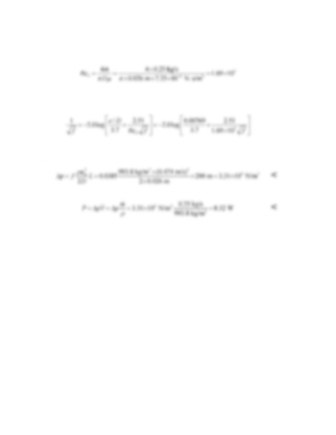
When the surface is fouled, the inner diameter is smaller, Dfoul = D – 2t = 30 mm – 4 mm = 26
mm. The Reynolds number becomes:
and the velocity is
2
/ ( / 4)
m
um D
ρπ
=
= 0.474 m/s. The friction coefficient can be found from Equation
8.20 (or estimated from Figure 8.3) with relative roughness e/D = 0.2 mm/26 mm = 0.00769:
The solution is f = 0.0385.Then from Equations 8.22ab, the pressure drop and pumping power
are:
COMMENTS: Fouling has a significant effect on the pumping power, due to both reducing the cross-
sectional area and the effect of roughness on turbulence.
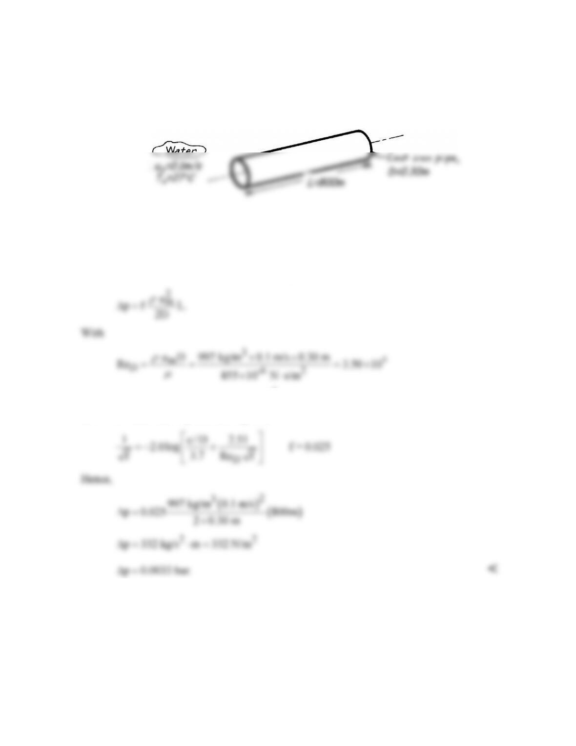
PROBLEM 8.3
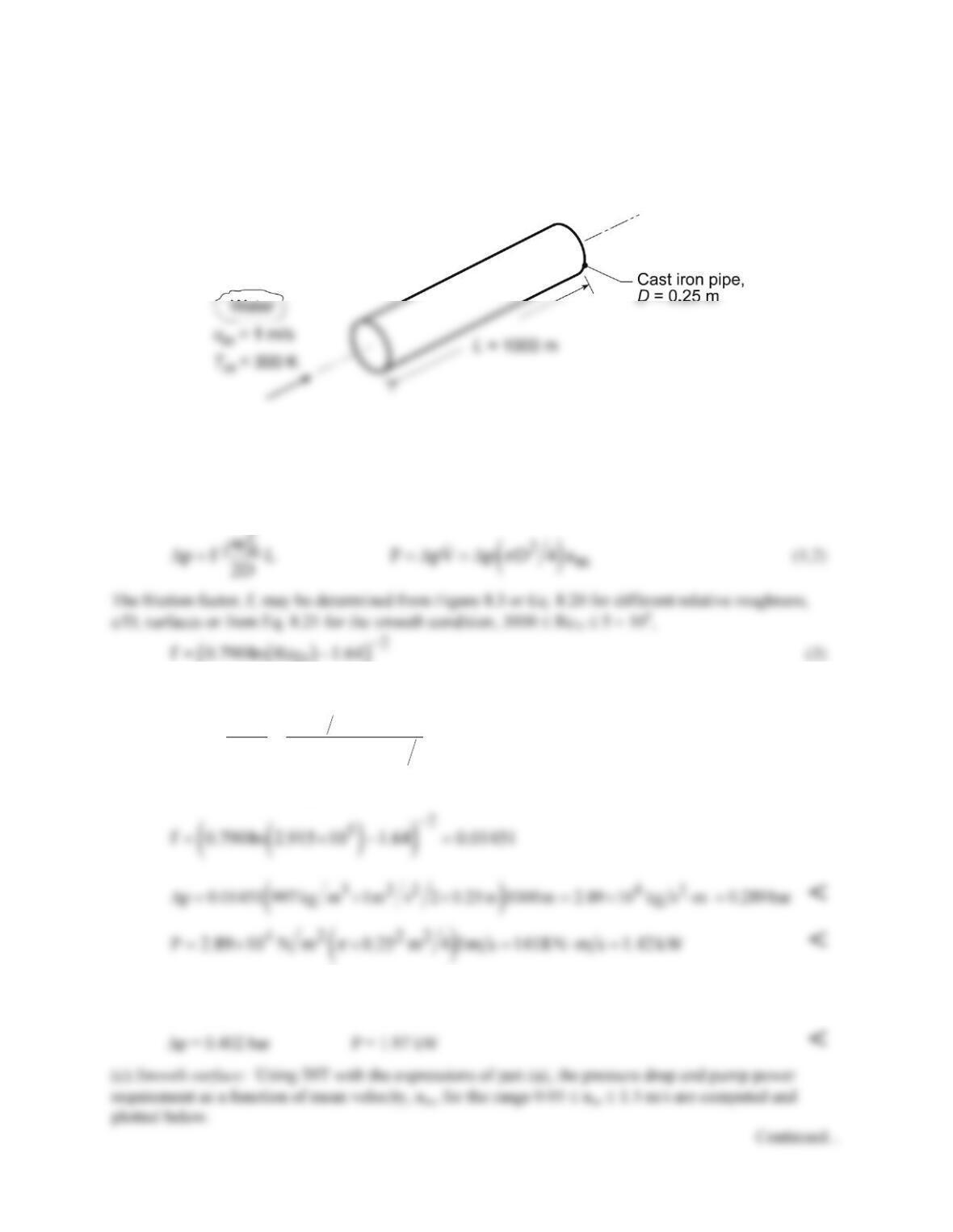
KNOWN: Temperature and mean velocity of water flow through a cast iron pipe of
prescribed length and diameter.
FIND: Pressure drop.
SCHEMATIC:
ASSUMPTIONS: (1) Steady-state conditions, (2) Fully developed flow, (3) Constant
properties.
PROPERTIES: Table A-6, Water (300 K): ρ = 997 kg/m3, m = 855 × 10–6 N⋅s/m2.
ANALYSIS: From Eq. 8.22, the pressure drop is
the flow is turbulent and with e = 2.6 ×10⁻⁴ m for cast iron (see Fig. 8.3), it follows that e/D =
867 × 10-6 and from Eq. 8.20 (or Fig. 8.3)
COMMENTS: For the prescribed geometry, L/D = (800/0.30) = 2670 >> (xfd,h/D)turb ≈ 10,
and the assumption of fully developed flow throughout the pipe is justified.
PROBLEM 8.4
KNOWN: Temperature and velocity of water flow in a pipe of prescribed dimensions.
FIND: Pressure drop and pump power requirement for (a) a smooth pipe, (b) a cast iron pipe with a
clean surface, and (c) smooth pipe for a range of mean velocities 0.05 to 1.5 m/s.
SCHEMATIC:
ASSUMPTIONS: (1) Steady, fully developed flow.
PROPERTIES: Table A.6, Water (300 K): ρ = 997 kg/m3, m = 855 × 10-6 N⋅s/m2, ν = m/ρ = 8.576 ×
10-7 m2/s.
ANALYSIS: From Eq. 8.22a and 8.22b, the pressure drop and pump power requirement are
D
where the Reynolds number is
5
m
D72
u D 1m s 0.25 m
Re 2.915 10
8.576 10 m s
ν
−
×
= = = ×
×
(4)
(a) Smooth surface: from Eqs. (3), (1) and (2),
(b) Cast iron clean surface: with e = 260 mm, the relative roughness is e/D = 260 × 10-6 m/0.25 m = 1.04
× 10-3. From Figure 8.3 or Eq. 8.20 with ReD = 2.92 × 10⁵, find f = 0.021. Hence,
PROBLEM 8.4 (Cont.)
0.6
1
4
8
Pressure drop, deltap (bar)
Pump power, P (kW)
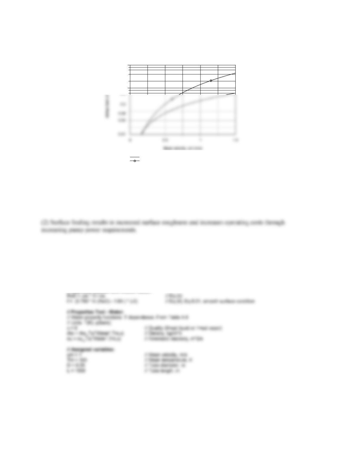
The pressure drop is a strong function of the mean velocity. So is the pump power since it is proportional
to both Dp and the mean velocity.
COMMENTS: (1) Note that L/D = 4000 >> (xfd,h/D) ≈ 10 for turbulent flow and the assumption of
fully developed conditions is justified.
(3) The IHT Workspace used to generate the graphical results follows.
// Pressure drop:
deltap = f * rho * um^2 * L / ( 2 * D ) // Eq (1); Eq 8.22a
deltap_bar = deltap / 1.00e5 // Conversion, Pa to bar units
Power = deltap * ( pi * D^2 / 4 ) * um // Eq (2); Eq 8.22b
Power_kW = Power / 1000 // Useful for scaling graphical result
// Reynolds number and friction factor:
PROBLEM 8.5
KNOWN: Number, diameter and length of tubes and flow rate for an engine oil cooler.
FIND: Pressure drop and pump power (a) for flow rate of 24 kg/s and (b) as a function of flow rate for
the range 10 ≤
m
≤ 30 kg/s.
SCHEMATIC:
L = 2.5 m
Tm = 300 K
D = 10 mm
.
ASSUMPTIONS: (1) Fully developed flow throughout the tubes.
PROPERTIES: Table A.5, Engine oil (300 K): ρ = 884 kg/m3, m = 0.486 kg/s⋅m.
ANALYSIS: (a) Considering flow through a single tube, find
( )
( )
D
4 24 kg s
4m
Re 251.5
D 25 0.010 m 0.486 kg s m
πm π
= = =
⋅
(1)
Hence, the flow is laminar and from Equation 8.19,
Equation 8.22a yields
The pump power requirement from Equation 8.22b,
(b) Using IHT with the expressions of part (a), the pressure drop and pump power requirement as a
function of flow rate,
m
, for the range 10 ≤
m
≤ 30 kg/s are computed and plotted below.
50
60
70
150
200
250
PROBLEM 8.5 (Cont.)
In the plot above, note that the pressure drop is linear with the flow rate since, from Eq. (2), the friction
factor is inversely dependent upon mean velocity. The pump power, however, is quadratic with the flow
rate.
COMMENTS: (1) If there is a hydrodynamic entry region, the average friction factor for the entire tube
length would exceed the fully developed value, thereby increasing Dp and P.
(2) The IHT Workspace used to generate the graphical results follows.
/* Results: base case, part (a)
P_kW ReD deltap_bar f mu rho um D N
// Reynolds number and friction factor
ReD = 4 * mdot1 / (pi * D * mu) // Reynolds number, Eq (1)
f = 64 / ReD // Friction factor, laminar flow, Eq. 8.19, Eq. (2)
// Average velocity and flow rate
// Pressure drop and power
deltap = f * rho * um^2 * L / (2 * D) // Pressure drop, N/m^2
// Input variables
D = 0.01 // Diameter, m
// Engine Oil property functions : From Table A.5
rho = rho_T(“Engine Oil”,Tm) // Density, kg/m^3
mu = mu_T(“Engine Oil”,Tm) // Viscosity, N·s/m^2
PROBLEM 8.6
KNOWN: The x-momentum equation for fully developed laminar flow in a parallel-plate channel
2
2
dp d u
constant
dx dy
m
= =
FIND: Following the same approach as for the circular tube in Section 8.1: (a) Show that the velocity
profile, u(y), is parabolic of the form
where um is the mean velocity expressed as
and –dp/dx =
D
p/L where
D
p is the pressure drop across the channel of length L; (b) Write the
expression defining the friction factor, f, using the hydraulic diameter as the characteristic length, Dh;
What is the hydraulic diameter for the parallel–plate channel? (c) The friction factor is estimated from
the expression
D
f C Re=
where C depends upon the flow cross-section as shown in Table 8.1;
SCHEMATIC:
ASSUMPTIONS: (1) Fully developed laminar flow, (2) Parallel-plate channel, a << b.
PROPERTIES: Table A-4, Air (300 K, 1 atm): m = 184.6 × 10⁻⁷ N⋅s/m2, ν = 15.89 × 10⁻⁶ m2/s.
ANALYSIS: (a) The x-momentum equation for fully developed laminar flow is
Since the longitudinal pressure gradient is constant, separate variables and integrate twice,
Fluid
Parallel plate channel
y
xL
a = 5 mm
+a/2
Fluid
Parallel plate channel
y
xL
a = 5 mm
+a/2
PROBLEM 8.6 (Cont.)
The integration constants are determined from the boundary conditions,
( )
y0
du 0 u a/2 0
dy
=
= =
to find
giving
( )
The mean velocity is
Substituting Eq. (3) for dp/dx into Eq. (2) find the velocity distribution in terms of the mean velocity
( ) ( )
2
m2
3y
uy u 1
2a/2
= −
< (4)
(b) The friction factor follows from its definition, Eq. 8.16,
where the hydraulic diameter for the channel using Eq. 8.66 is
since a << b.
(c) Substituting for the pressure gradient, Eq. (3), and rearranging, find using Eq. (6),
PROBLEM 8.6 (Cont.)
This result is in agreement with Table 8.1 for the cross–section with b/a → ∞ where
C = 96. <
(d) For the conditions shown in the schematic, with air properties evaluated at 300 K, using Eqs. (3)
and (8), find
The flow is laminar since ReDh < 2300, and from Eq. 8.3, the laminar entry length is
We conclude that the flow is not fully developed, and the friction factor in the entry region will be
higher than for fully developed conditions. Hence, for the same pressure drop, the mean velocity will
be less than our estimate.
PROBLEM 8.7
KNOWN: Water, engine oil and NaK flowing in a 20 mm diameter tube, temperature of the
fluids.
FIND: (a) The mean velocity as well as hydrodynamic and thermal entrance lengths, for a flow
rate of 0.01 kg/s and mean temperature of 366 K, (b) The mass flow rate as well as hydrodynamic
and thermal entrance lengths for water and oil at a mean velocity of 0.02 m/s at mean
temperatures of 300 and 400 K.
SCHEMATIC:
ASSUMPTIONS: (1) Constant properties.
PROPERTIES:
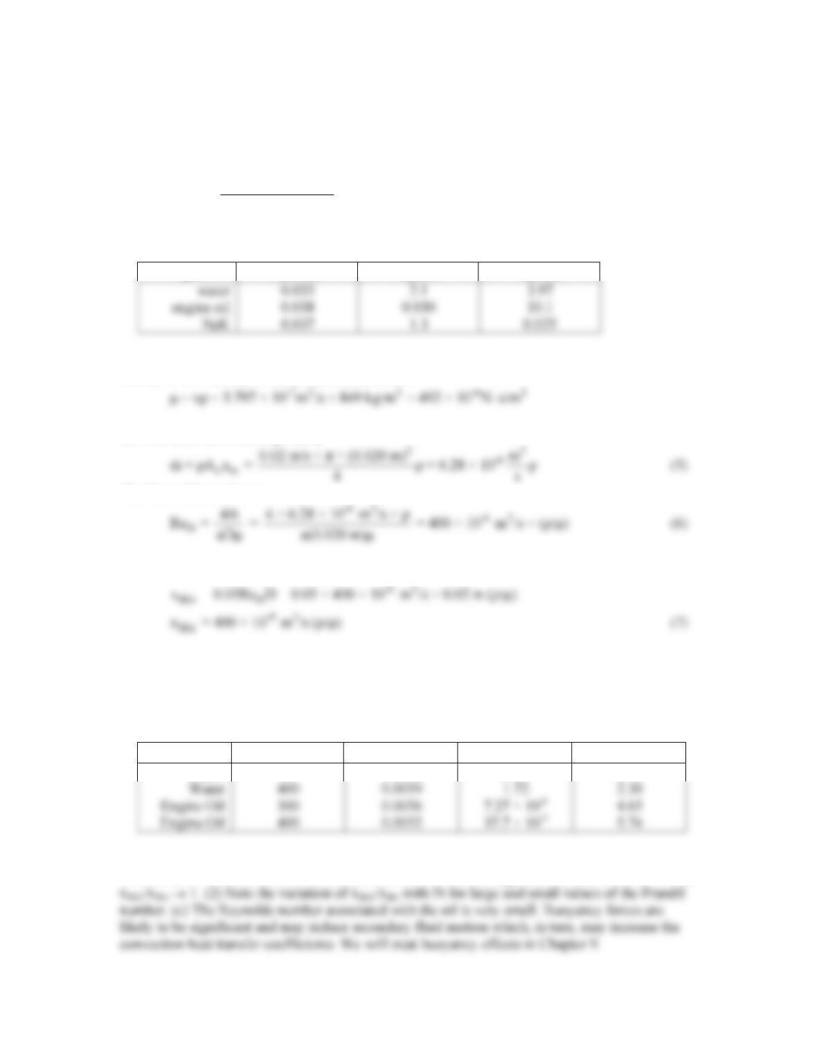
Liquid T(K) Table ρ(kg/m3) m(N⋅s/m2) ν(m2/s) Pr
Water 300 A.6 997 855 × 10-6 – 5.83
ANALYSIS: (a) The mean velocity is given by
22
mc
u = m ρA = 0.01 kg/s/ (0.020m) /4 = 31.8 kg/s m /
ρπ ⋅ ρ
(1)
The Reynolds number is
The hydrodynamic entrance length is
PROBLEM 8.7 (Cont.)
The thermal entrance length is
fd,t D fd,h
x = 0.05Re DPr = x Pr
-6
636 × 10 kg/s m
= Pr
μ
⋅
(4)
Solving Equations (1), (3) and (4) yields <
Liquid
um (m/s)
xfd,h (m)
xfd,t (m)
where, for the NaK, μ is found from the definition
(b) The mass flow rate is given by
The Reynolds number is
The hydrodynamic entrance length is
The thermal entrance length is
-9 3
fd,t fd,h
x = x Pr = 400 × 10 m /s (ρ/μ) Pr
(8)
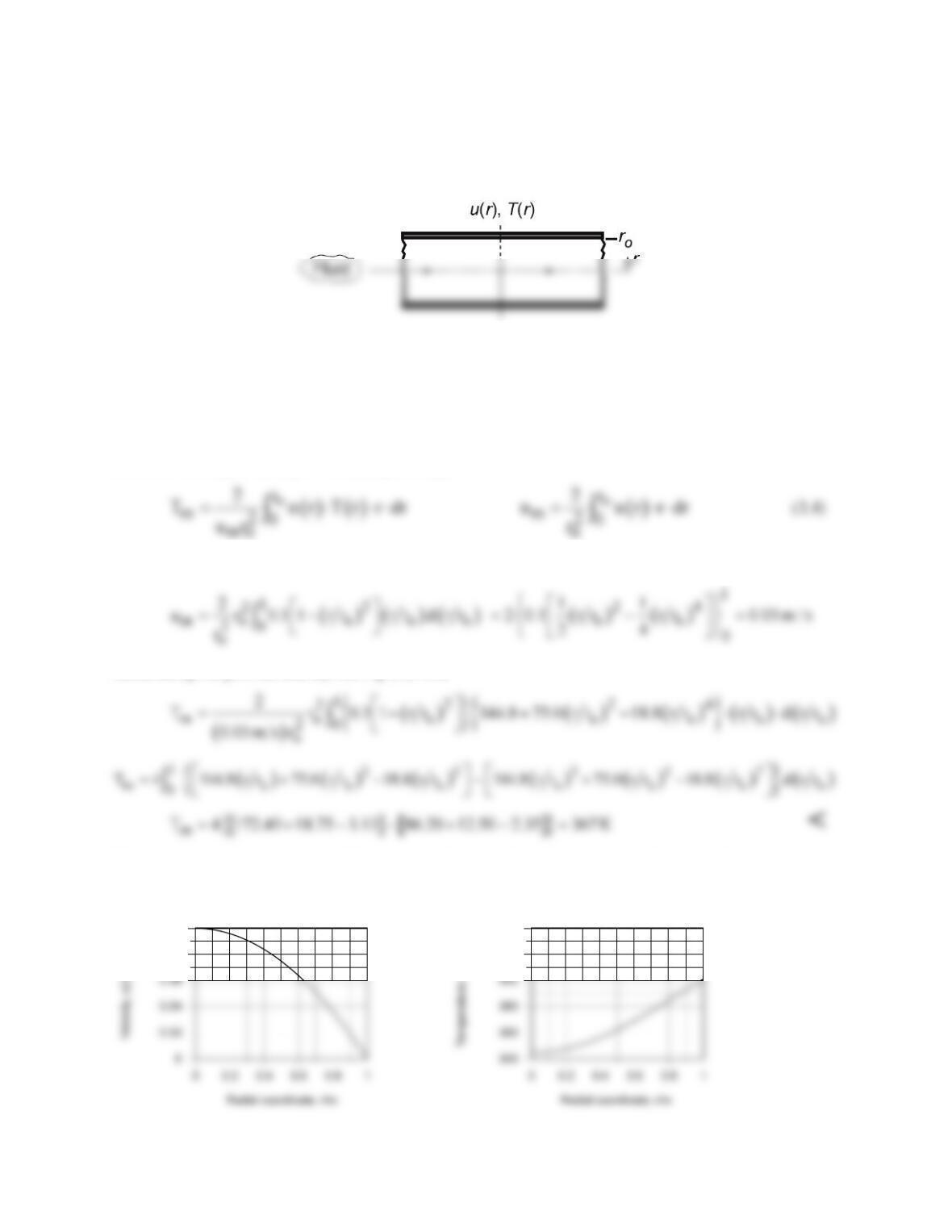
Solving Equations (5), (7) and (8) yields <
Liquid
T (k)
m
(kg/s)
x
fd,h
(m)
x
fd,t
(m)
Water
300
0.0063
0.464
2.72
COMMENTS: (1) As the momentum and thermal diffusivities approach similar values (Pr → 1)
PROBLEM 8.8
KNOWN: Velocity and temperature profiles for laminar flow in a tube of radius ro = 10 mm.
FIND: Mean (or bulk) temperature, Tm, at this axial position.
SCHEMATIC:
ASSUMPTIONS: (1) Laminar incompressible flow, (2) Constant properties.
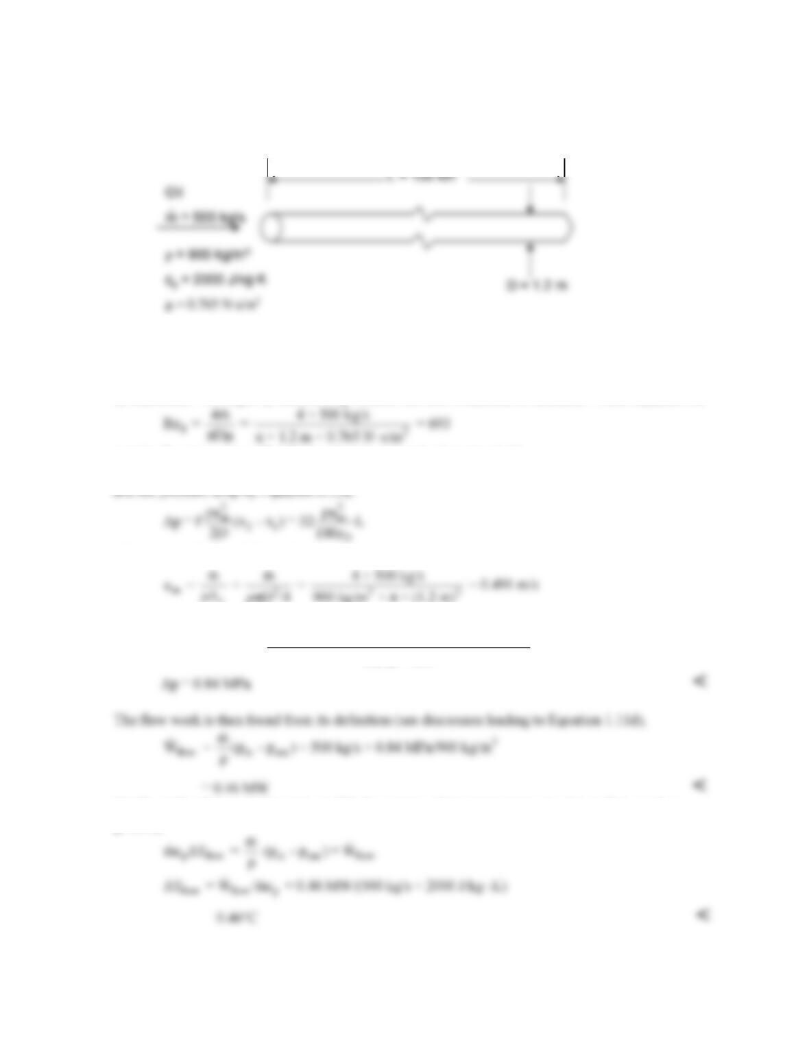
ANALYSIS: The prescribed velocity and temperature profiles, (m/s and K, respectively) are
u(r) = 0.1 [1-(r/ro)2] T(r) = 344.8 + 75.0 (r/ro)2 – 18.8 (r/ro)4 (1,2)
For incompressible flow with constant cv in a circular tube, from Eq. 8.26, the mean temperature and um,
the mean velocity, from Eq. 8.8 are, respectively,
Substituting the velocity profile, Eq. (1), into Eq. (4) and integrating, find
Substituting the profiles and um into Eq. (3), find
The velocity and temperature profiles appear as shown below. Do the values of um and Tm found above
compare with their respective profiles as you thought? Is the fluid being heated or cooled?
0.08
0.1
420
440
PROBLEM 8.9
KNOWN: Flow rate and properties of oil flowing in pipe. Dimensions of pipe.
FIND: Pressure drop, flow work, temperature rise caused by flow work.
SCHEMATIC:
ASSUMPTIONS: (1) Steady–state, (2) Incompressible flow, (3) Negligible kinetic and potential
energy changes, (4) No work other than flow work.
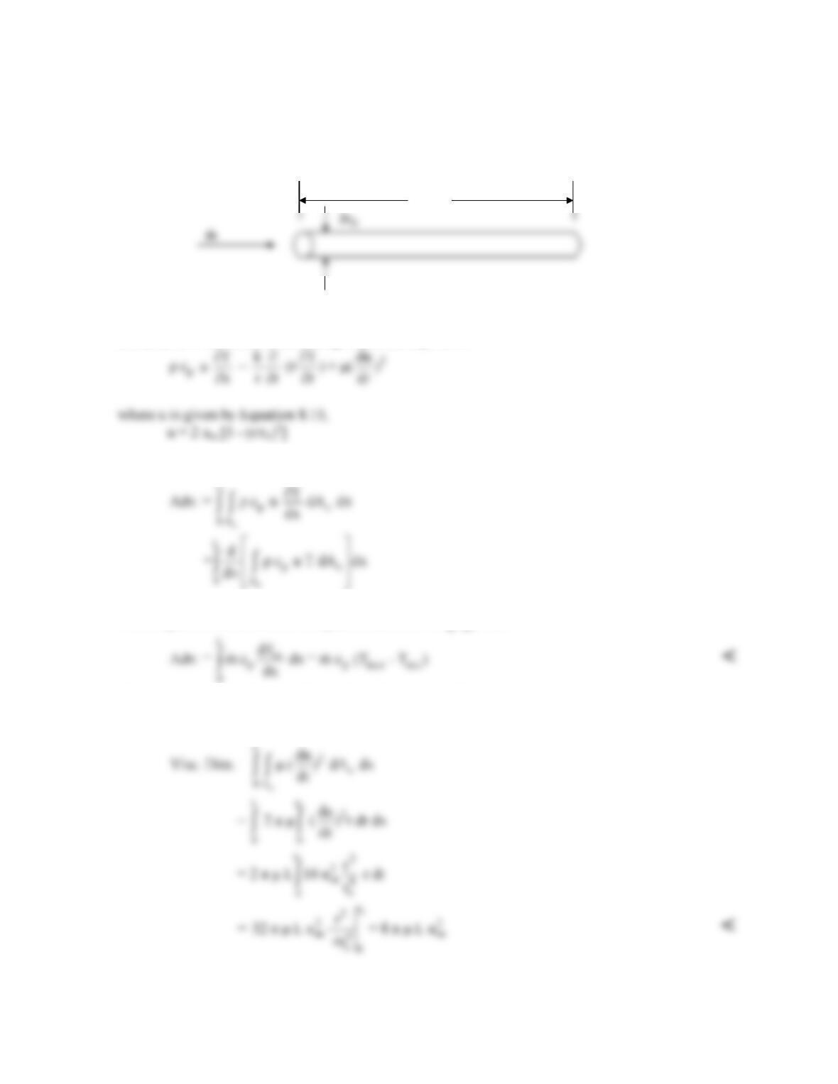
ANALYSIS: We begin by determining whether the flow is laminar or turbulent. From Equation 8.6
and the flow is laminar. The friction factor is given by Equation 8.19,
f = 64/ReD
where um can be found from
mc
m = ρu A
:
c
Thus
32 5
in out
32 × 900 kg/m × (0.491 m/s) × 100,000 m
p – p = Δp = = 8.4 × 10 Pa
1.2 m × 693
Finally, with reference to Equation 1.12d, the portion of the temperature rise due to flow work is
given by
COMMENTS: Despite the long length of pipeline and high viscosity of the oil, which results in a
large pressure drop, the temperature rise due to the flow work is quite small.
PROBLEM 8.10
KNOWN: Thermal energy equation describing laminar, fully developed flow in a circular pipe with
viscous dissipation.
FIND: (a) Left hand side of equation integrated over the pipe volume, (b) viscous dissipation term
integrated over the same volume, (c) temperature rise caused by viscous dissipation.
SCHEMATIC:
ASSUMPTIONS: (1) Steady–state, (2) Laminar, (3) Fully–developed.
ANALYSIS: (a) The thermal energy equation is given as
Integrating the advection term on the left-hand side over a section of the pipe of length L, we have
From Equation 8.25, the term in square brackets is
pm
mc T
, thus
which coincides with the right-hand side of Equation 8.34.
(b) Integrating the viscous dissipation term, we have
Continued…
L
L
PROBLEM 8.10 (Cont.)
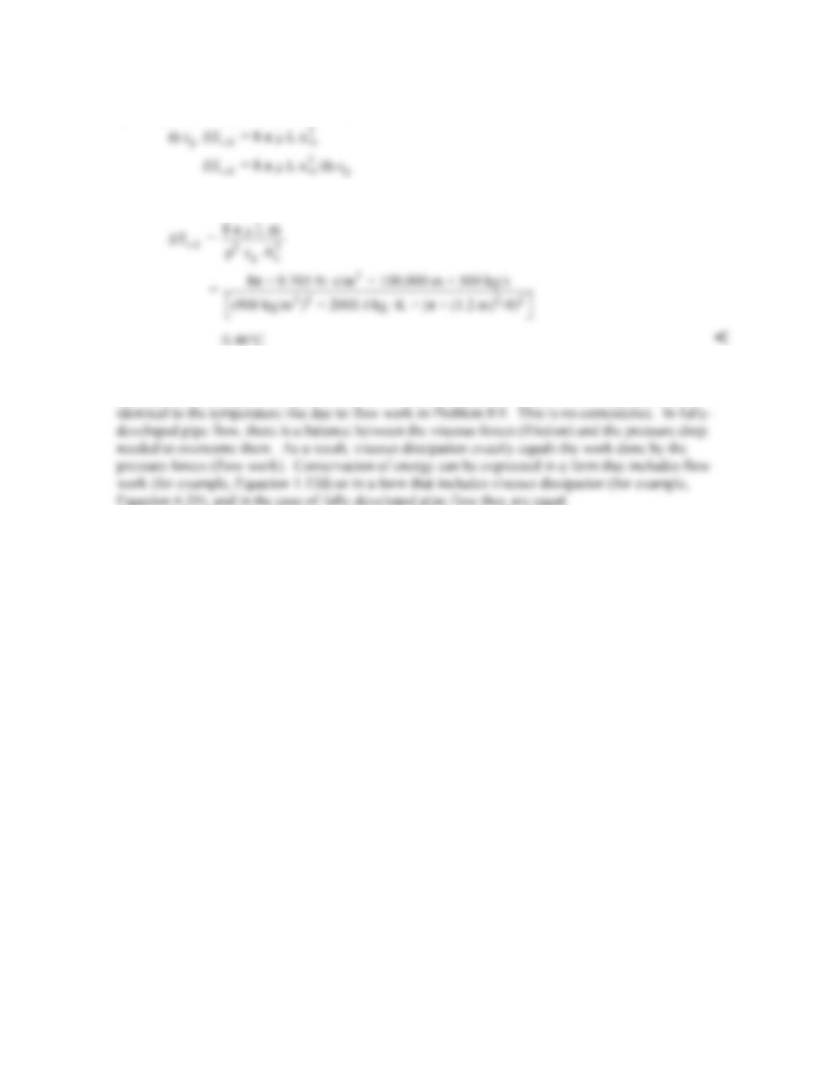
(c) Using the values from Problem 8.9,
where um =
c
m/ A .ρ
Thus
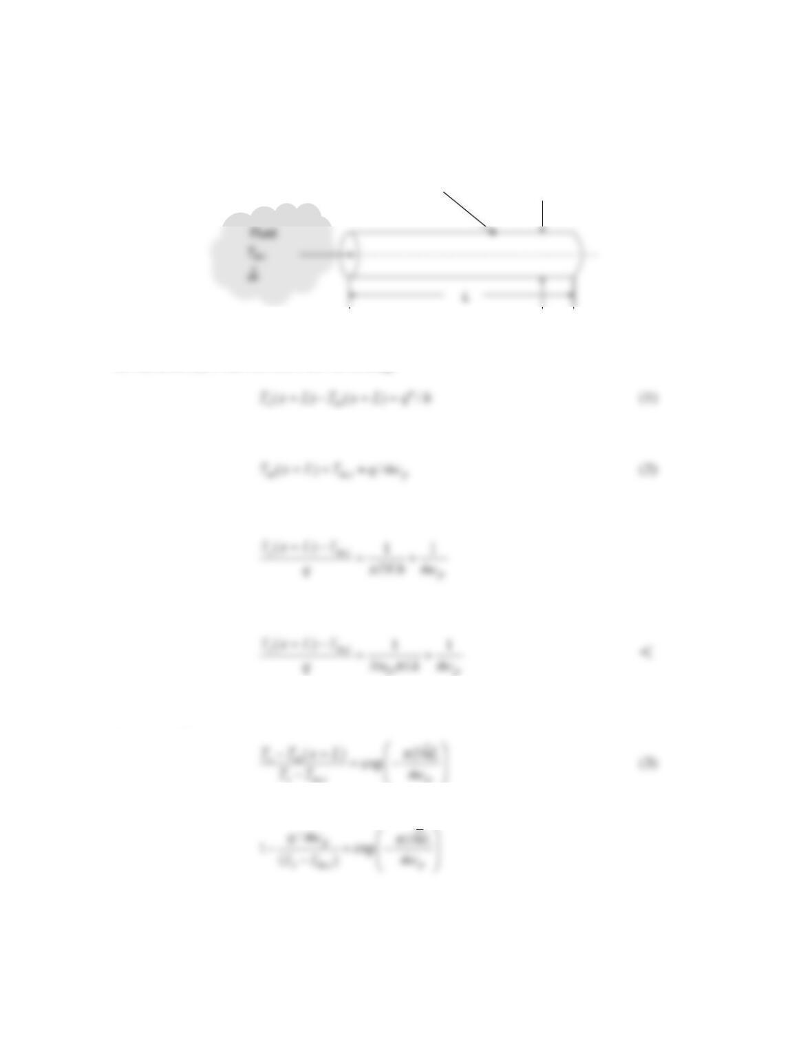
COMMENTS: (1) Even in the case of a long pipe with a highly viscous fluid, the temperature rise
due to viscous dissipation is quite small. (2) The temperature rise due to viscous dissipation is
PROBLEM 8.11
KNOWN: Mass flow rate in a circular tube, tube length and diameter, thermal conditions.
FIND: (a) Expression for (Ts(x = L) – Tm,i)/q for constant heat flux conditions, (b) (Ts – Tm,i )/q for
constant surface temperature conditions.
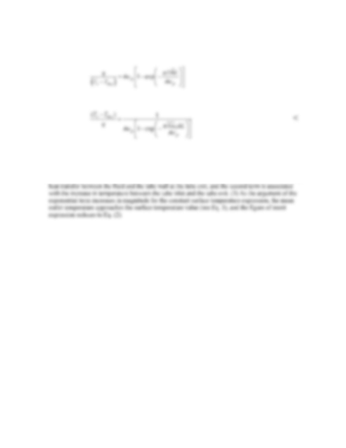
SCHEMATIC:
ASSUMPTIONS: (1) Constant properties.
ANALYSIS (a) From Newton’s law of cooling,
and from an energy balance on the entire tube,
Combining Eqs. (1) and (2) and noting that
q q DL
π
′′
=
yields
Substituting the expression for the local Nusselt number, NuD = hD/k gives
(b) From Eq. (8.41b)
,
s mi p
Combining Eqs. (2) and (3) yields
Continued…
Constant heat flux or constant surface temperature
D
PROBLEM 8.11 (Cont.)
which may be rearranged to yield
or
COMMENTS: (1) The ratio on the LHS is a figure of merit that, in many applications, is sought to
be minimized. (2)The two terms on the RHS of the final expression for the constant heat flux case may
be thought of as thermal resistances. The first term on the RHS is a thermal resistance associated with
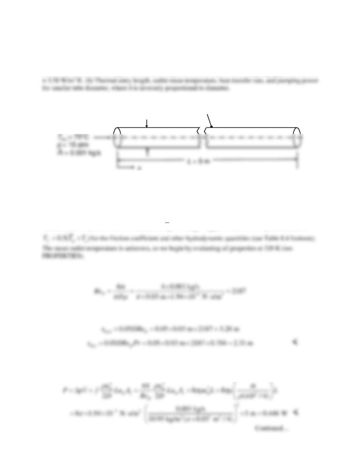
PROBLEM 8.12
KNOWN: Mass flow rate, pressure, and inlet temperature of dry, compressed air. Diameter, length, and
surface temperature of tube.
FIND: (a) Thermal entry length, outlet mean temperature, heat transfer rate, and pumping power when h
SCHEMATIC:
D= 30 mm
Dry air
T
s
= 25°C
h= 3.58 W/m
2
∙K
for fully-developed conditions
ASSUMPTIONS: (1) Steady-state conditions, (2) Constant properties, (3) Incompressible fluid with
negligible viscous dissipation.
PROPERTIES: Table A-4, Air, (T = 320 K):
m
= 1.94 × 10⁻⁵ N⋅s/m2,
ρ
(10 atm) = 10
ρ
(1 atm) =
10(1.095 kg/m3) = 10.95kg/m3, cp = 1008 J/kg⋅K, Pr = 0.704.
ANALYSIS: Properties must be evaluated at
0.5( )
T TT= +
for heat transfer quantities, and at
(a) The Reynolds number is:
The flow is laminar and the entry lengths are given by:
Since the tube is 5 m long, the flow can be treated as hydrodynamically and thermally fully developed.
The friction coefficient can be found from Equation 8.19, and the pumping power from Equations 8.22ab: