Problem 8.57
Air flows though the mitered bend shown in the figure below at a rate of 5 cfs . To help
straighten, the flow after the bend, a set of 0.25-in.- diameter drinking straws is placed in the
pipe as shown. Estimate the extra pressure drop between points (1) and (2) caused by these
straws.
Solution 8.57
The extra pressure drop, Δ,
p
is equal to the pressure drop through the length of the straws
minus the pressure drop in that 12 in. length of the pipe without the straws. That is
(1)
(2) 12 in.
Tightly packed 0.25-in.-diameter,
12-in.-long straws
Thus,
2
33
32
12in. 1 slug ft lb
0.0215 2.38 10 6.37 1.04 10
12in. 2 s
ft ft
ns
p−−
Δ
=×=×
(1)
Transition range
Laminar flow
Wholly turbulent flow
0.1
0.09
0.08
0.07
0.06
0.05
0.04
0.05
0.04
0.03
0.02
0.015
Thus, in each 0.5in. by 0.5in. cross section, there are four straws, or a total of
That is, only about 2% of the flow is in the gap region – neglect this amount.
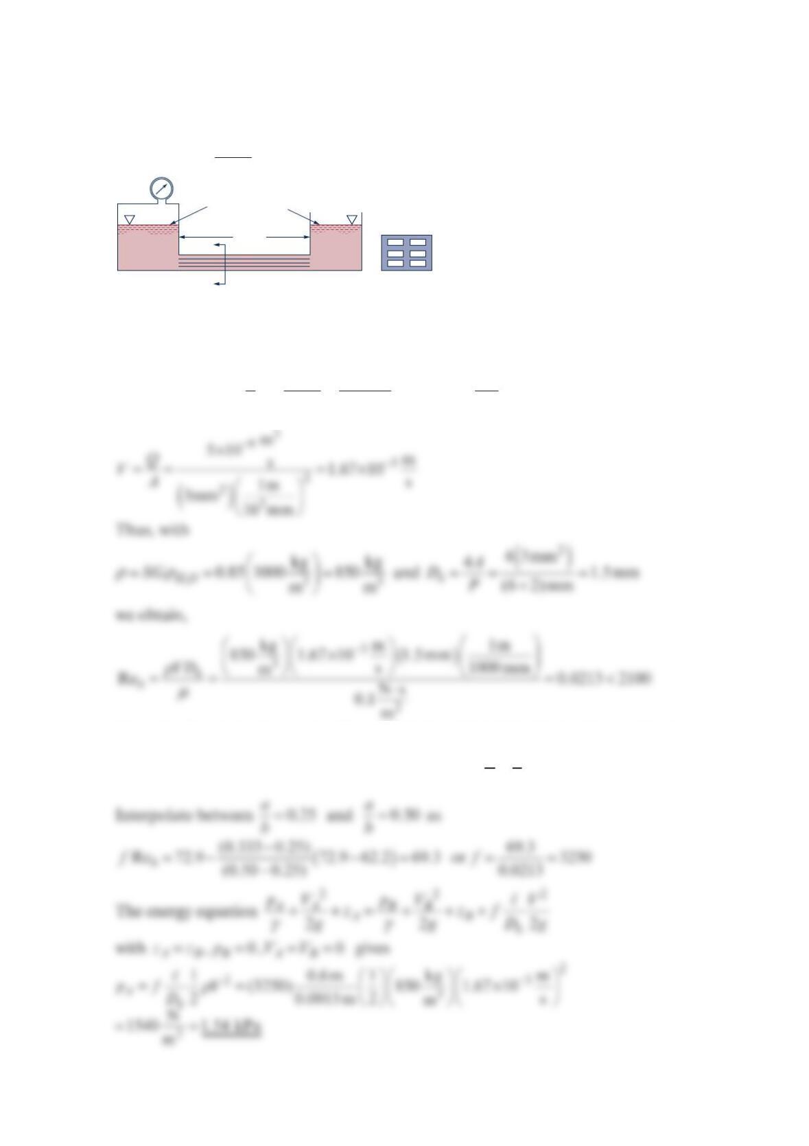
Problem 8.58
As shown in the figure below, water flows from one tank to another through a short pipe
whose length is n times the pipe diameter. Head losses occur in the pipe and at the entrance
and exit. Determine the maximum value of nif the major loss is to be no more than 10% of
the minor loss and the friction factor is 0.02 .
Solution 8.58
If =
major minor
00
10
LL
hh
, then
D
𝓵
=
nD
Problem 8.59
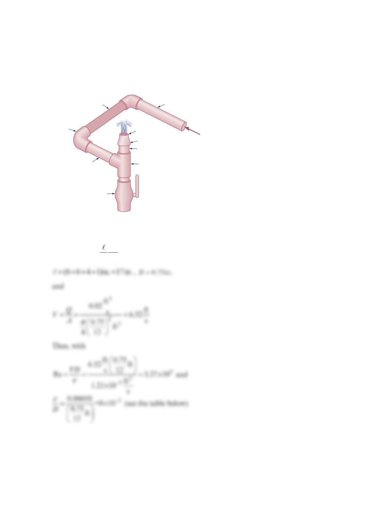
Water flows steadily through the 0.75-in. -diameter galvanized iron pipe system shown in
the figure below at a rate of 0.020 cfs . Your boss suggests that friction losses in the straight
pipe sections are negligible compared to losses in the threaded elbows and fittings of the
system. Do you agree or disagree with your boss? Support your answer with appropriate
calculations.
Solution 8.59
=
2
Major loss 2
V
fDg
where
6-in. length 6-in. length
4-in. length
Closed ball
valve
90° threaded
elbows 0.60-in. dia.
Reducer
Q
= 0.020 cfs
1-in. length
Tee
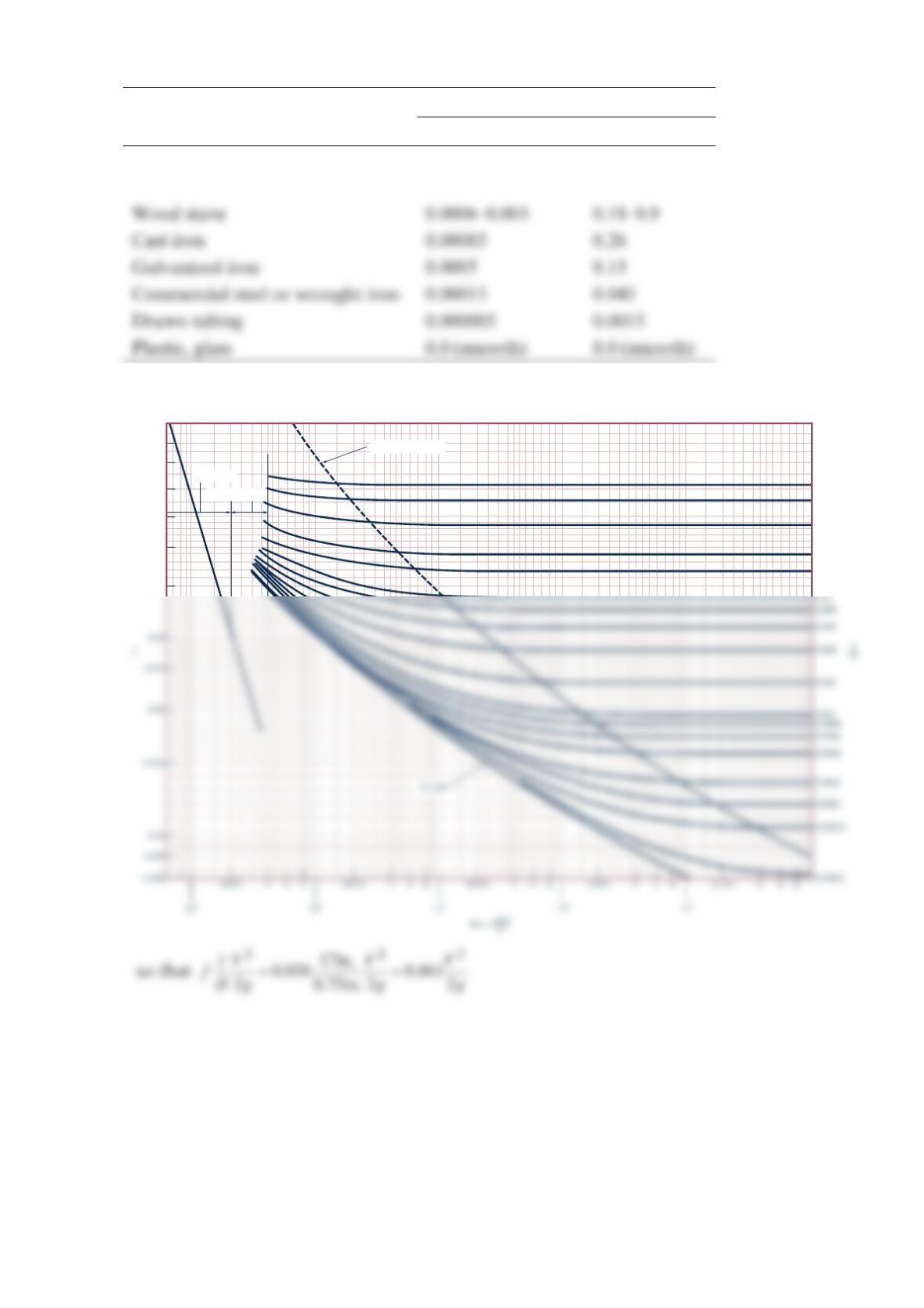
Equivalent Roughness,
ε
Pipe Feet Millimeters
Riveted steel 0.003–0.03 0.9–9.0
Concrete 0.001–0.01 0.3–3.0
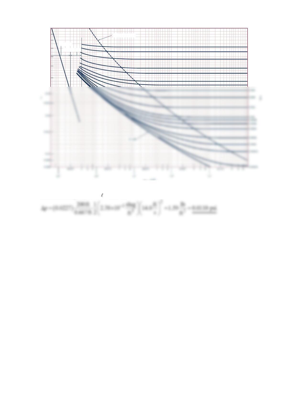
we obtain (see the figure below) =0.038f
Transition range
Laminar flow
Wholly turbulent flow
0.1
0.09
0.08
0.07
0.06
0.05
0.04
0.05
0.04
0.03
0.02
0.015
A
1
A
2
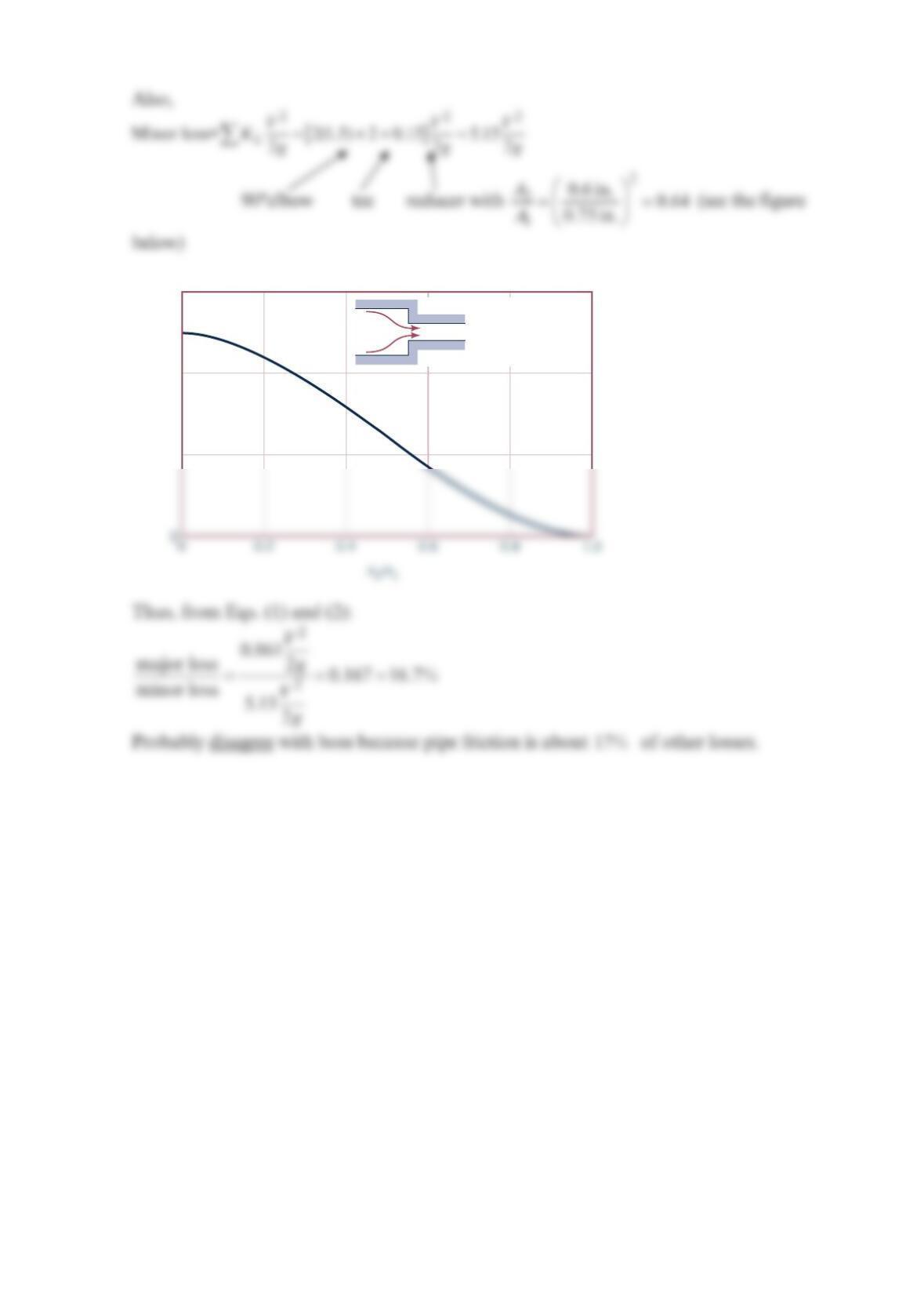
h
L
=
K
L
V2
2
___
2
g
0.6
0.4
0.2
K
L
Problem 8.60
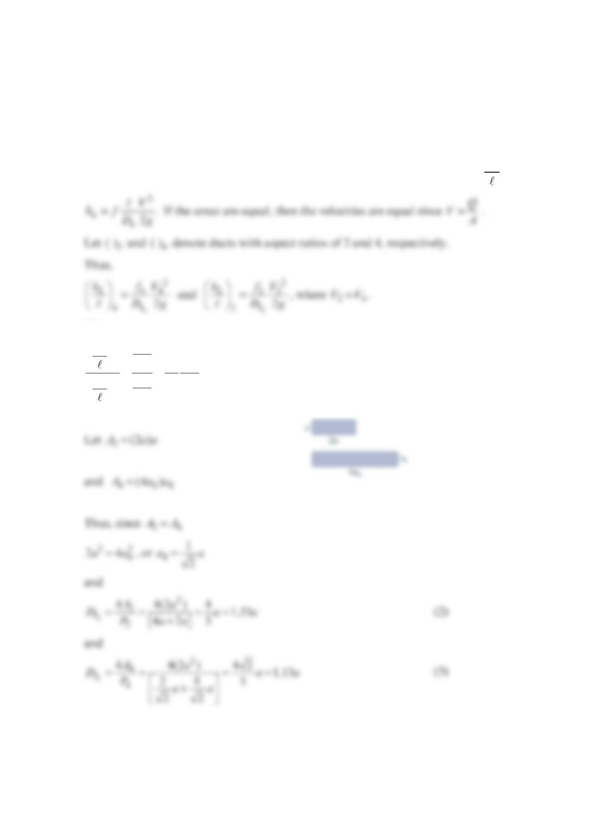
Given two rectangular ducts with equal cross-sectional area, but different aspect ratios
(width/height) of 2 and 4, which will have the greater frictional losses? Explain your
answer.
Solution 8.60
The duct with the greater losses is the one with the largest head loss per length, L
h, where
Hence,
==
42
4
2
4
44
22
2
L
hh
Lh
h
f
h
DD
f
f
h
f
D
D
(1)
so that
In general,
ε
=
Re,ff D in such a way that if
ε
D increases, f increases, and if Re
decreases, f increases. This is seen from the Moody chart as indicated below.
Thus, whether the flow is laminar or turbulent, it follows that >
42
ff
. If follows from Eq.
(4) that
laminar
turbulent
f
•
(4)
•
Problem 8.61
A viscous oil with a specific gravity =0.85SG and a viscosity of ⋅0.10 Pa s flows from tank
A to tank B through the six rectangular slots indicated in the figure below. If the total
flowrate is
3
mm
3
0 s and minor losses are negligible, determine the pressure in tank A.
Solution 8.61
For each slot, −
==×
3
33
9
3
1mm 1m m
30 5 10
6s s
10 mm
Q so that
Thus, the flow is laminar with =Re 69.3
h
f (see Table 8.3 Friction Factors for Laminar
Flow in Noncircular Ducts [Data from Ref. 18] with =1
3
a
b ).
0.6 m
Same elevation
a
a
AB
Each slot
3 mm
× 1 mm
Section
a−a
Problem 8.62
Air at standard temperature and pressure flows at a rate of 7.0 cfs through a horizontal,
galvanized iron duct that has a rectangular cross-sectional shape of 12 in. by 6 in.
Estimate the pressure drop per 200 ft of duct.
Solution 8.62
For a horizontal duct,
γρ
Δ= = 2
1
2
L
h
p
hf V
D where =Q
VA
or
Thus, from Eq. (1), with =200 ft ,
Transition range
Laminar flow
Wholly turbulent flow
0.1
0.09
0.08
0.07
0.06
0.05
0.04
0.05
0.04
0.03
0.02
0.015
0.01
0.008
Re = VD
_____
μ
ρ
Problem 8.63
Water at 20 C° flows through a concentric annulus of inner diameter =
1 2.0 cmD and
outer diameter =
2 4.0 cm.D The surface roughness is 0.002 cm. Calculate the frictional
pressure loss per unit length for a flowrate of 3
0.01 m /s.
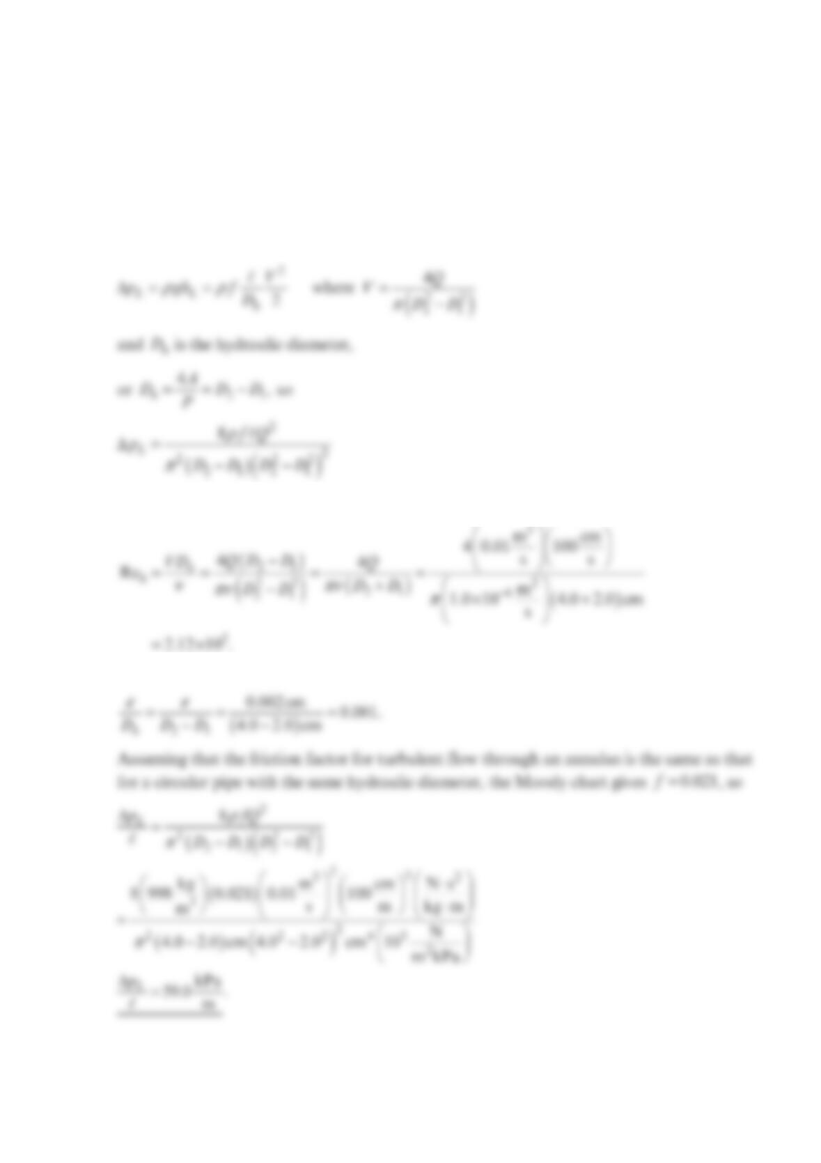
Solution 8.63
The frictional pressure loss is
The Reynolds number is found using
Now
Problem 8.64
Air at standard conditions flows through a horizontal 1 ft by 1.5 ft rectangular wooden
duct at a rate of
3
ft
5000 min. Determine the head loss, pressure drop, and power supplied by
the fan to overcome the flow resistance in 500 ft of the duct.
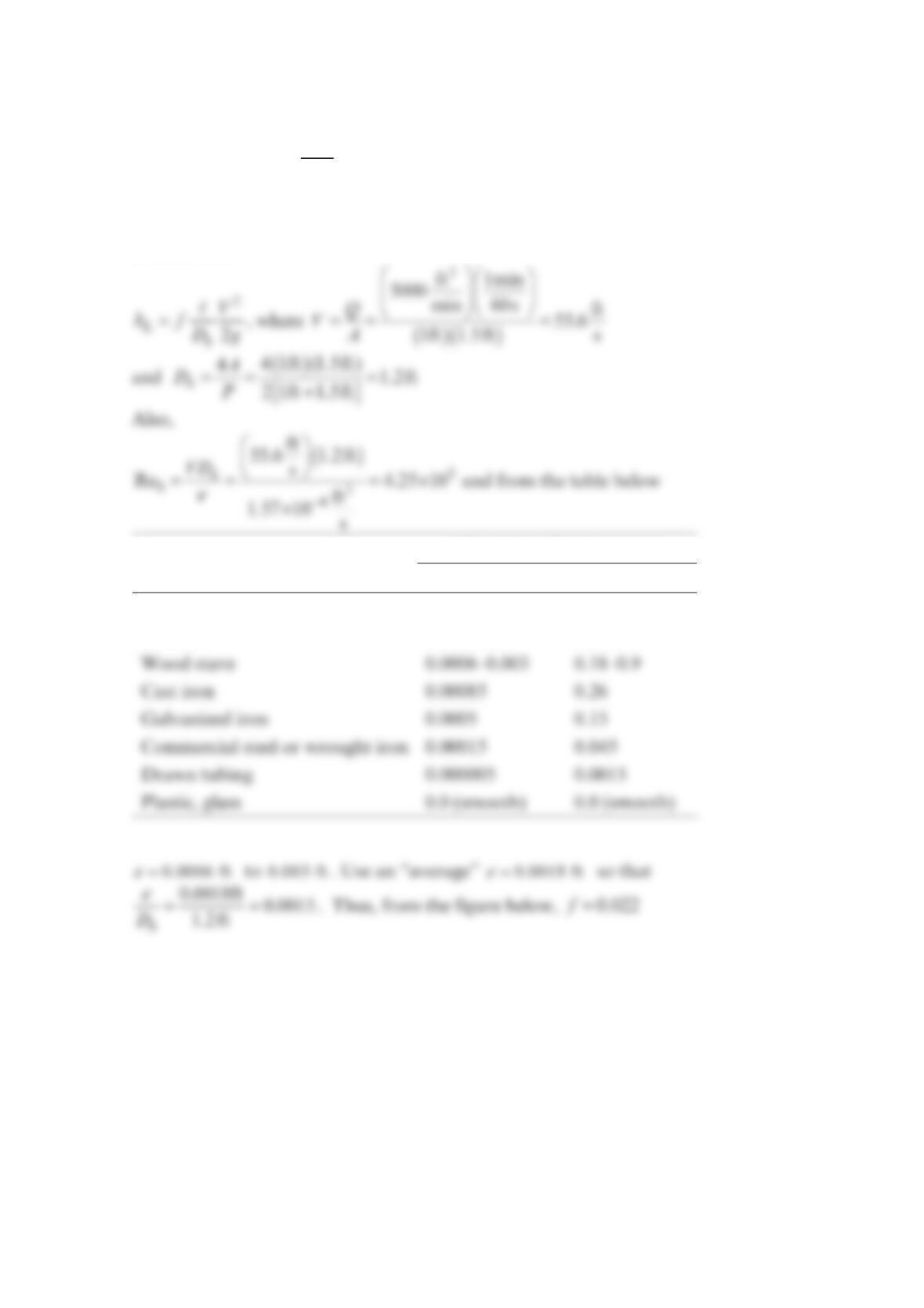
Solution 8.64
Equivalent Roughness,
ε
Pipe Feet Millimeters
Riveted steel 0.003–0.03 0.9–9.0
Concrete 0.001–0.01 0.3–3.0