Problem 8.109
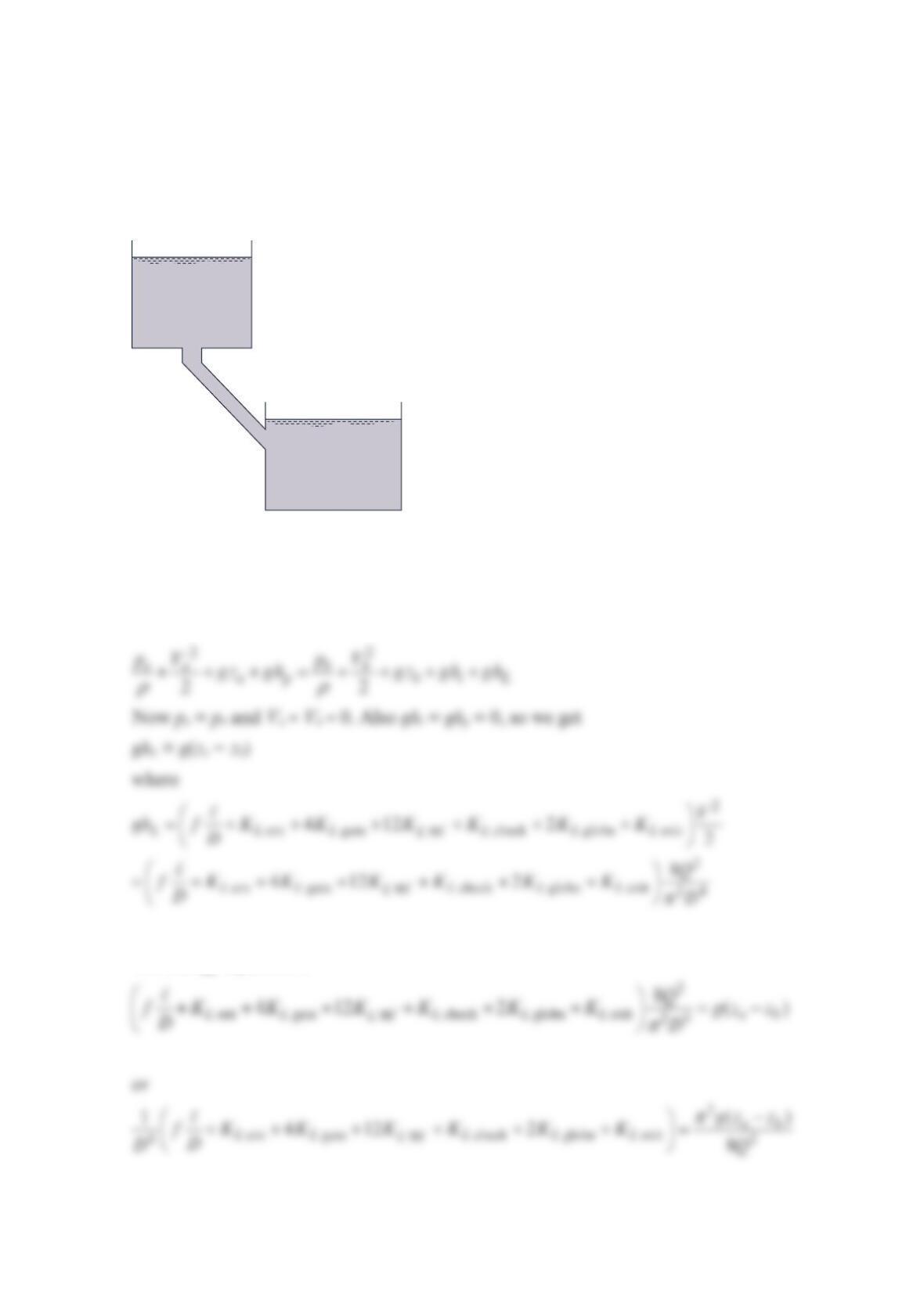
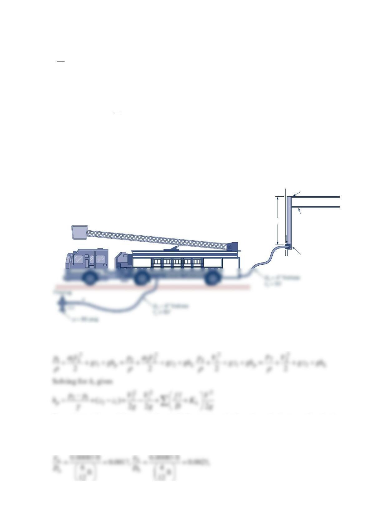
It is necessary to deliver 270 ft3/min of water from reservoir A to reservoir B, as shown in
the figure below. The connecting piping consists of four fully open gate valves, 12 regular
90° elbows, one swing check valve, two fully open globe valves, and 3000 ft of commercial
steel pipe. Find the minimum diameter for steel pipe needed to obtain this flowrate. All
fittings and valves have flanged connections. Assume a square-edged entrance.
Solution 8.109
Write the mechanical energy equation from the reservoir A water surface (a) to the reservoir
B water surface (b).
The energy equation is
Elevation 150.0 ft
Reservoir
A
Elevation 25.0 ft
Reservoir
B
For a square-edged entrance, standard elbows and a swing check valve, Table 8.2 and
Figure 8.22 give
and the energy equation gives
or
the Moody chart gives f = 0.015, and Table 8.2 gives
KL gate = 0.15, KL 90° = 0.3, and KL globe = 10.
The left-hand side of Eq. (1) gives
Problem 8.110
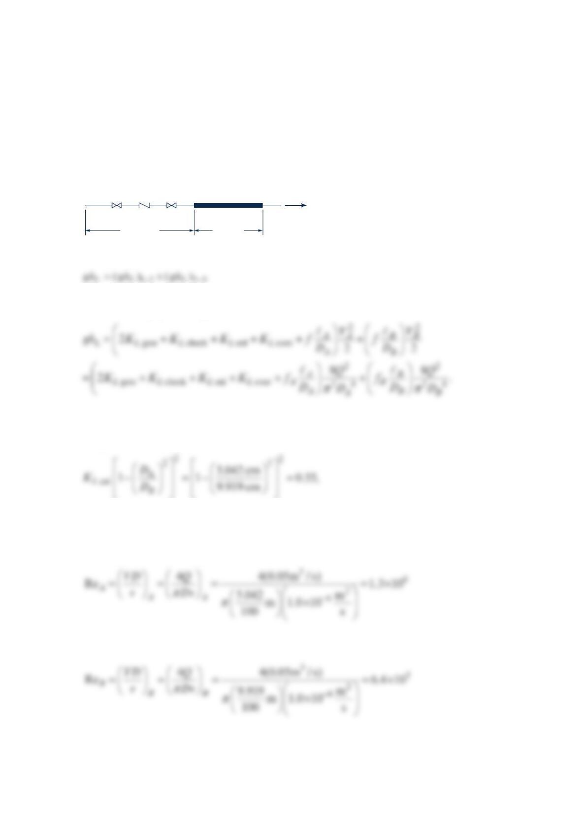
A 10-m-long, 5.042-cm I.D. copper pipe has two fully open gate valves, a swing check
valve, and a sudden enlargement to a 9.919-cm I.D. copper pipe. The 9.919-cm copper pipe
is 5.0 m long and then has a sudden contraction to another 5.042-cm copper pipe. Find the
head loss for a 20 °C water flowrate of 0.05 m3/s.
Solution 8.110
The energy loss is
12 23
LL L
−−
where the loss coefficients for the enlargement and contraction are based on the velocity in
the 5.042 cm pipe. This gives
Table 8.2, Figure 8.26 (or the equation), and Figure 8.25 give
gate check
K
0.15, 2
LL
K
K
==
and
cont 0.4
L
K
≈
Using Table B.2, the Reynolds numbers are
and
ℓ
B
= 5 m
gate
swing
check
1 gate 2 3
ℓ
A
= 10 m
ID
= 5.042 cm
ID
= 9.919 cm
Q
= 0.05
m
3
/s
20 °C water
Using Table 8.1 for copper pipe (drawn tubing),
The Moody chart gives
fA = 0.0118 and fB = 0.013.
The energy loss is
Problem 8.111
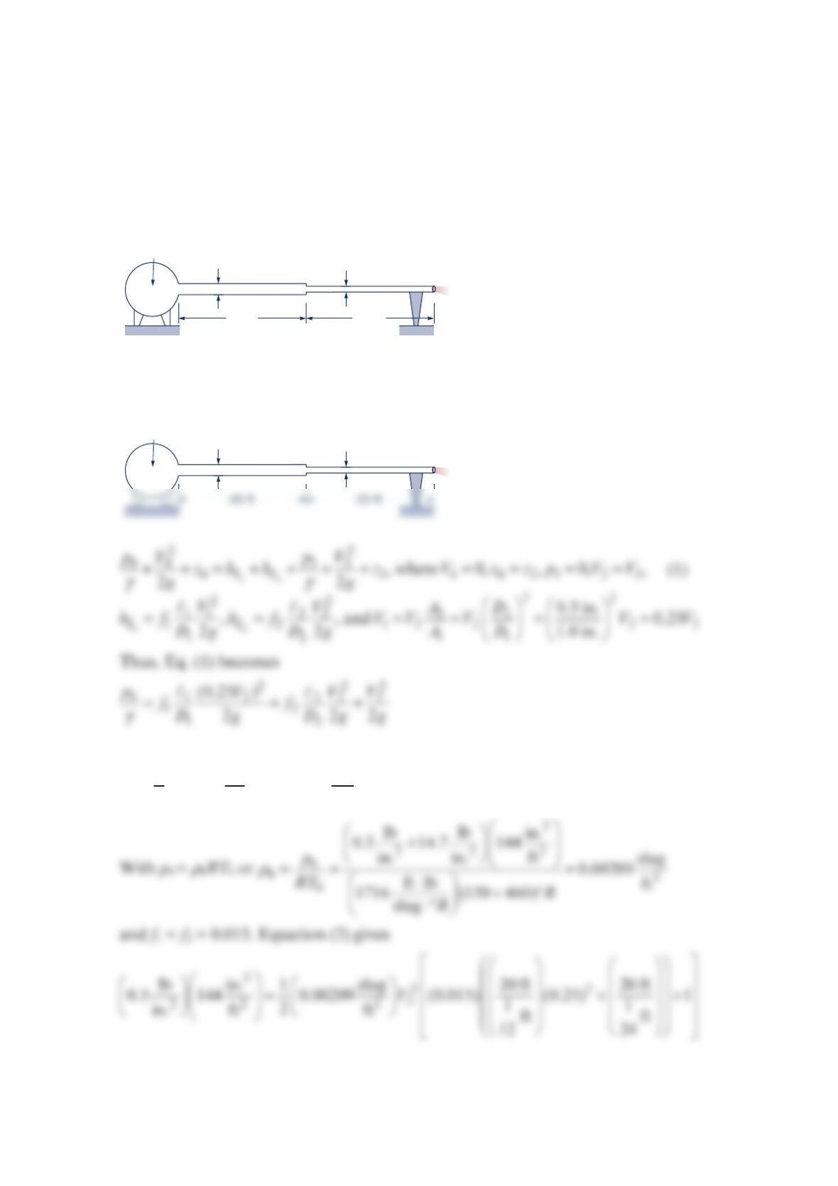
Air, assumed incompressible, flows through the two pipes shown in the figure below.
Determine the flowrate if minor losses are neglected and the friction factor in each pipe is
0.015. Determine the flowrate if the 0.5-in.-diameter pipe were replaced by a
1
-in.-diameter
pipe. Comment on the assumption of incompressibility.
Solution 8.111
or
22
12
021 2
12
1(0.25) 1
2
p
Vf f
DD
ρ
=
+
+
(2)
p
= 0.5 psi
T
= 150°F
20 ft 20 ft
1 in. 0.50 in.
p
= 0.5 psi
T
= 150°F
1 in.
(0)
(1) (2)
0.50 in.
(3)
•
or
=
2
ft
90.4 s
V. Thus,
π
== =
23
22
1ftft
ft 90.4 0.123
424 s s
QAV
If both pipes were 1 in. diameter, then V1 = V2 and Eq. (1) becomes
Hence,
or
=
2
ft
91.7 s
V Thus,
π
== =
23
22
1ftft
ft 91.7 0.500
412 s s
QAV
Since p =
ρ
RT it follows that
Problem 8.112
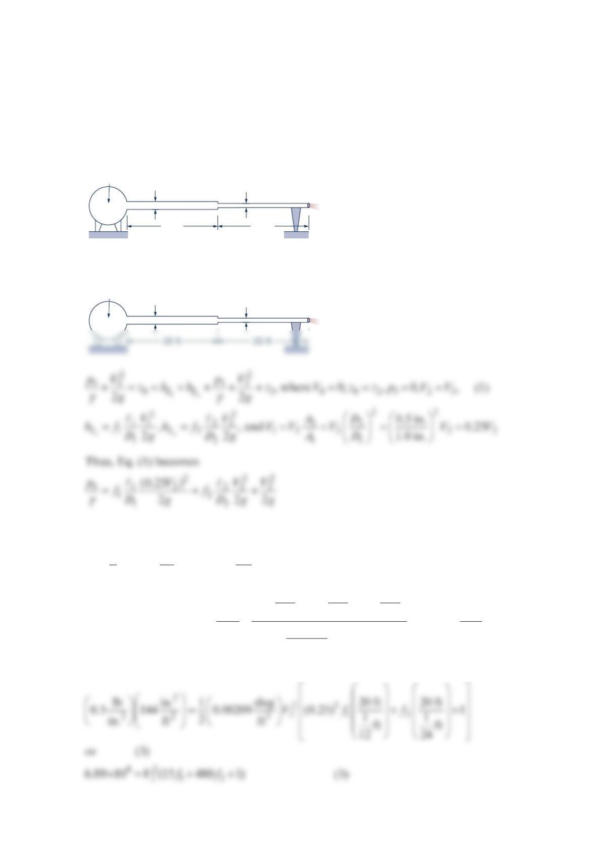
Air, assumed incompressible, flows through the two pipes shown in the figure below.
Determine the flowrate if minor losses are neglected, the pipes are galvanized iron and the
friction fsactors are not known a priori. Determine the flowrate if the 0.5-in.-diameter pipe
were replaced by a 1-in.- diameter pipe. Comment on the assumption of incompressibility.
Solution 8.112
or
22
12
021 2
12
1(0.25) 1
2
p
Vf f
DD
ρ
=
+
+
(2)
With
ρ
0 =
ρ
0RT0 or
2
222
0
03
0
lb lb in.
0.5 14.7 144
in. in. ft slug
0.00209
ft lb f
(150 460) t
1716 slug
p
RT R
R
ρ
+
+
== =
⋅°
⋅°
.
Equation (2) becomes
p
= 0.5 psi
T
= 150°F
20 ft 20 ft
1 in. 0.50 in.
p
= 0.5 psi
T
= 150°F
1 in.
(0)
(1) (2)
0.50 in.
(3)
•
Also from Table 8.1 Equivalent Roughness for New Pipes [Adapted from Moody (Ref. 7)
and Colebrook (Ref. 8)]
and
11 2 2
12
Re ,Re
VD V D
vv
==, where from Table B.2 Physical Properties of Air at Standard
Atmospheric Pressure (BG/EE Units)
µ
ρ
−
−
×
=×
⋅
==
2
72
4
03
4.18 10 ft
2.00 10
slug s
0.00209 ft
lb s
ft
v
Hence,
and
−
==
×
2
22
2
4
1ft
24
Re 208
ft
2.00 10 s
V
V (7)
For turbulent flow, the Colebrook equation gives 12.51
2.0 log 3.7 Re
D
ff
ε
=− +
(8)
Thus,
Thus, Eq. (1) becomes
212
022
2
11
2
p
Vf D
ρ
+
=+
or
Thus,
ππ
== = =
23
2
22 22
1ftft
ft 62.2 0.339
4412 s s
QAV DV
Note: Since p =
ρ
RT, it follows that
p
Problem 8.114
Normal octane at 68 °F (
ν
= 8.31 × 10⁻⁶ ft2/s) is to be delivered at a flowrate of 3.0 gal/min
through a 2.0-in. schedule 40 commercial steel pipe (with an actual inside diameter of 2.067
in.). Energy losses are important, so consideration is being given to expanding the pipe to a
3.0 in. schedule 40 commercial steel pipe (with an actual inside diameter of 3.068 in.), using
a 10° conical expansion. After a length ℓ of the 3.0-in. pipe, it is decreased to a 2.0-in.
schedule 40 commercial steel pipe with a gradual contraction ( 0.10
L
K
=, based on the
smaller diameter pipe flow). Find the minimum length ℓ so that the energy loss will be the
same as in a 2.0-in. pipe of length ℓ + 2(5.7 in.). See the figure below.
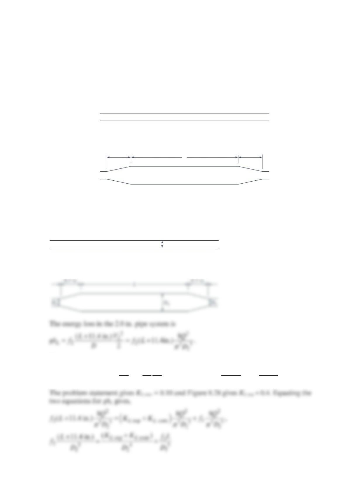
Solution 8.114
Consider the two piping systems:
The energy loss in the 3.0 in. pipe system is
() ()
2
222
3
2
exp cont 3 exp cont 3
24 25
323
88
.
22
LL L L L
V
VLQQ
gh K K f K K f L
DDD
ππ
=+ + =+ +
5.7 in.
Expansion Contraction3-in. pipe
2-in. pipe
5.7 in.
𝓵
D2
or
With the given diameters, D2 = 2.067 in. and D3 = 3.068 in., and known numerical values,
2
45
3
2
55
22
23 23
(11.4 in.)
0.4 0.1
(2.067 in.) (3.068 in.) .
(2.067 in.) (2.068 in.)
(0.5 0.766 )in. (1 1.532 )in. .
(0.484 0.139 ) (0.968 0.278 )
f
L
f
f
ff
Lff ff
+−
=
−
−−
==
−−
The friction factors are found using the Moody chart.
22
2
0.00015 ft 0.00087, 0.037,
2.067 ft
12
f
D
ε
== =
Problem 8.115
The flowrate between tank A and tank B shown in the figure below is to be increased by
30% (i.e., from Q to
1
.30Q) by the addition of a second pipe (indicated by the dotted lines)
running from node C to tank B. If the elevation of the free surface in tank A is 25 ft above
that in tank B, determine the diameter, D, of this new pipe. Neglect minor losses and
assume that the friction factor for each pipe is 0.02.
Solution 8.115
or
1
ft
6.05 s
V
=. Hence,
π
== =
23
11
6ftft
ft 6.05 1.188
412 s s
QAV
6-in. diameter;
600 ft long
6-in. diameter;
500 ft long
C
Diameter
D
, 500 ft long
A
B
6-in. diameter;
600 ft long
(1) (2)
(3)
6-in. diameter;
500 ft long
C
Diameter
D
, 500 ft long
A
B
(A)
•
(B)
•
For fluid flowing from A to B through pipes 1 and 2,
Hence, =
2
ft
2.60 s
V
For fluid flowing from A to B through pipes 1 and 3,
13
2
233
11
13
13
22
AL L
V
V
zhh f f
Dg Dg
=+= +
where
π
== =
3
3
32
2
33
3
ft
1.03 1.31
s
4
Q
VAD
D
Thus,
Problem 8.116
A 250-ft-high building has a 6.065-in.-diameter steel standpipe and a 100-ft-long
9
2
-in.-diameter
16 fire hose on each floor. The nearest fireplug is 100 ft from the standpipe’s
ground-level connection. Assume that fire-fighters connect a 6-in.-diameter, 50-ft-long fire
hose from the fireplug to the fire truck and a 4-in.-diameter, 50-ft-long fire hose from the
fire truck to the standpipe’s ground-level connection. The National Fire Protection
Association (NFPA) requires that a minimum pressure of 65 psig be maintained at the
connection of the 9
2
-in.-diameter
16 hose and the standpipe while maintaining a flowrate of
500 gal/min through the fire hose. What pressure rise must the pump on the fire engine
supply to satisfy the NFPA requirement for this building? The fire hydrant water pressure
is 80 psig and the water temperature is 60 °F. The connections are threaded.
Solution 8.116
Assume steady state and apply the mechanical energy equation to a streamline from point 1
to point 2 with ht = 0 to get
To evaluate f for each hose and the standpipe, assume the hose is equivalent to galvanized
iron so Table 8.1 gives
ε
a =
ε
b = 0.00085 ft and
ε
c = 0.00015 ft. Assume the firehose diameter
is the inside diameter and the stand pipe diameter is given as Dc = 6.065 in. assuming a
schedule 40 pipe. Then
(2)
•
b
L = 250‘
D
c
= 6
″
standpipe
P
min
= 65 psig
Q = 500 gpm
c
D
d
= 2
″
firehose
T
water
= 60 °F
9
__
16
and
Table B.1 gives 52
1.21 10 ft /s
ν
−
=× for 60 °F water. So
and
3
5
52
ft / s
4(500 gal / min) 448.8 gal / min
Re 2.32 10 ,
6.065 ft (1.21 10 ft / s)
12
c
π
−
==×
×
The Moody chart gives
and
2
22
3
lb in.
(65 80) 144
in. ft 250 ft 41.2 ft 14.5 ft 271 ft
lb
62.4 ft
−
=+++=
p
h
The pump pressure rise, assuming sea level elevation, is
Problem 8.117
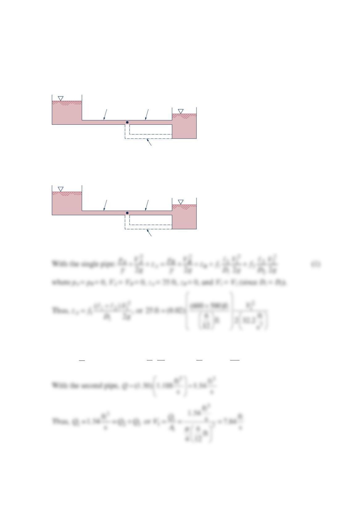
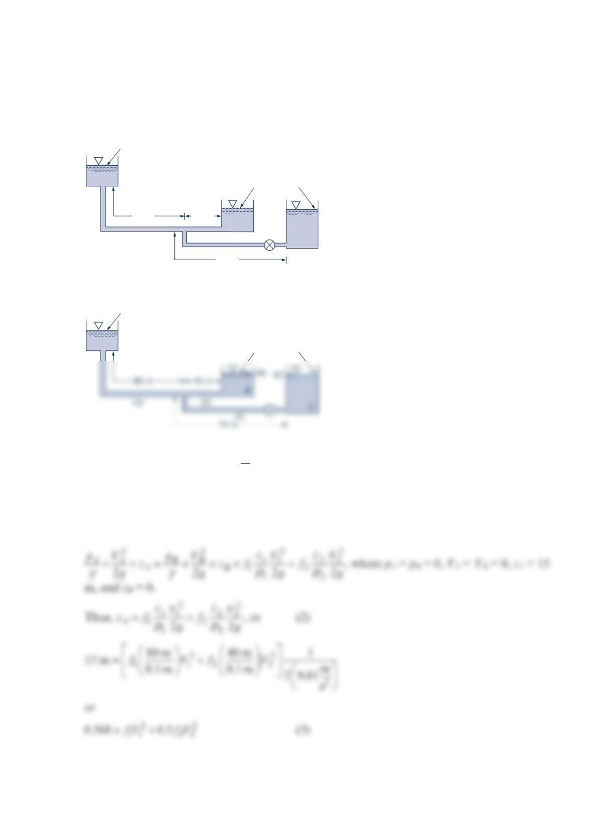
With the valve closed, water flows from tank A to tank B as shown in the figure below.
What is the flowrate into tank B when the valve is opened to allow water to flow into tank
C also? Neglect all minor losses and assume that the friction factor is 0.02 for all pipes.
Solution 8.117
4
Thus, since D1 = D2 = D3, it follows that
123
V
VV=+
(1)
Also, for fluid flowing from A to B,
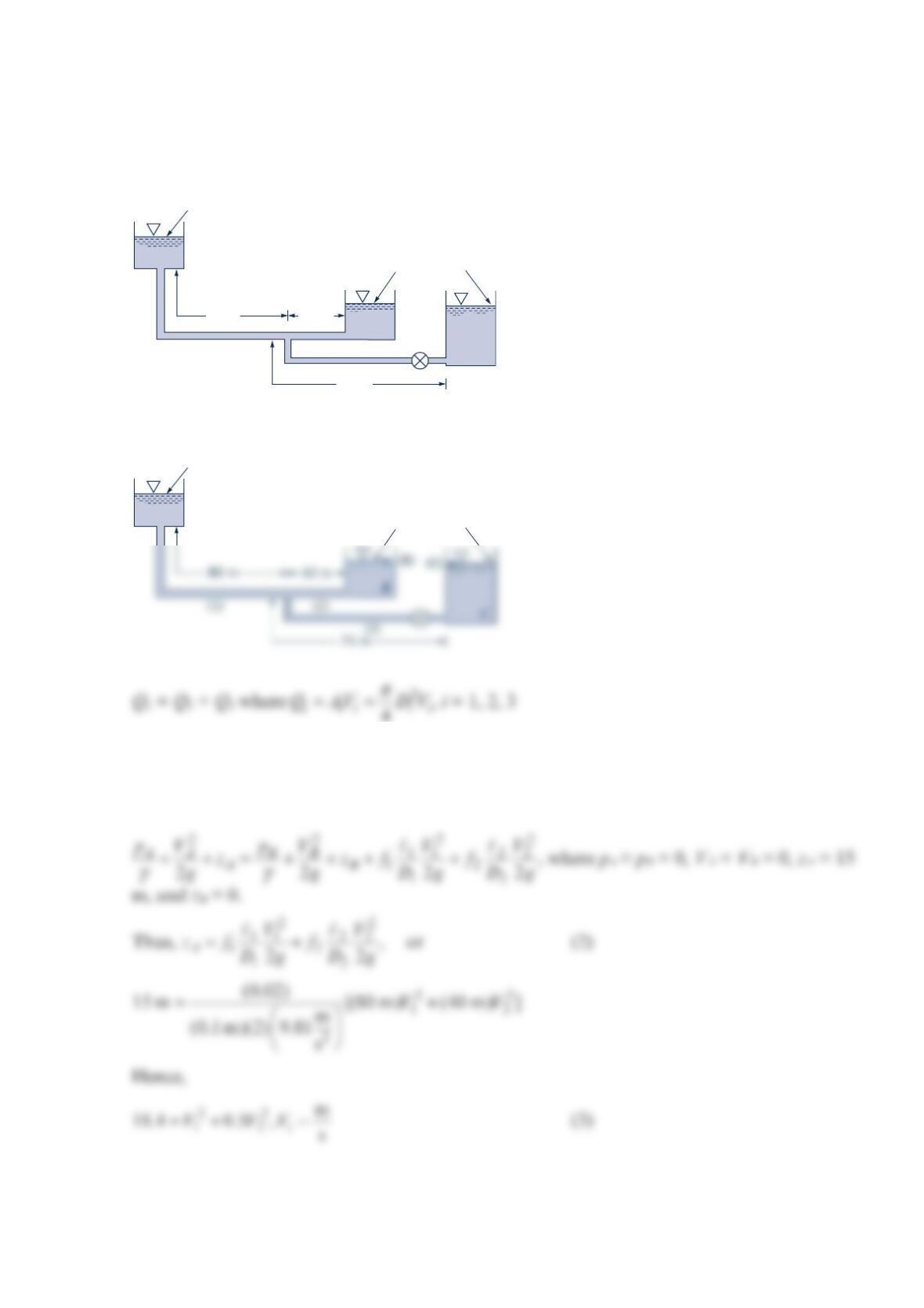
80 m 40 m
75 m
C
B
A
Elevations = 0
Elevation = 15 m
Diameter of each pipe = 0.10 m
A
Elevations = 0
Elevation = 15 m
(A)
•
Diameter of each pipe = 0.10 m
Similarly, for fluid flowing from A to C,
By comparing Eqs. (2) and (4), we find
2
233
22
23
23
22
V
V
ff
Dg Dg
=
or since f2 = f3 and D2 = D3,
= Thus, = or V2 = 1.369V3 (5)
Problem 8.118
With the valve closed, water flows from tank A to tank B as shown in the figure below.
What is the flowrate into tank B when the valve is opened to allow water to flow into tank
C also? Neglect all minor losses and assume the friction factors are not known, but the
pipes are steel pipes.
Solution 8.118
Q1 = Q2 + Q3 where 2
4
iii ii
QAV DV
π
== , i = 1, 2, 3
Thus, since D1 = D2 = D3 it follows that
123
V
VV=+
(1)
Also, for fluid flowing from A to B,
80 m 40 m
75 m
C
B
A
Elevations = 0
Elevation = 15 m
Diameter of each pipe = 0.10 m
A
Elevations = 0
Elevation = 15 m
(A)
•
Diameter of each pipe = 0.10 m
Similarly, for fluid flowing from A to C,
By comparing Eqs. (2) and (4), we find
2
233
22
23
23
22
V
V
ff
Dg Dg
=
or since and D2 = D3,
V
From the Colebrook equation, 12.51
2.0 log 3.7 Re
D
ff
ε
=− +
where from Table 8.1
equivalent Roughness for New Pipes [Adapted from Moody (Ref. 7) and
Colebrook (Ref. 8)]
ε
= 0.045 mm so that for each pipe, 4
0.045 mm 4.5 10
100 mm
ε
−
==×
iii
Solve six equations for six unknowns: Eqs. (1), (3), (5), (6), (7), and (8) for f1, f2, f3, V1, V2,
V3. Trial and error solution as follows:
From Eq. (5),
1
2
2
32
3
0.730 f
V
V
f
=
, which when combined with Eq. (1) gives