PROBLEM 8.81
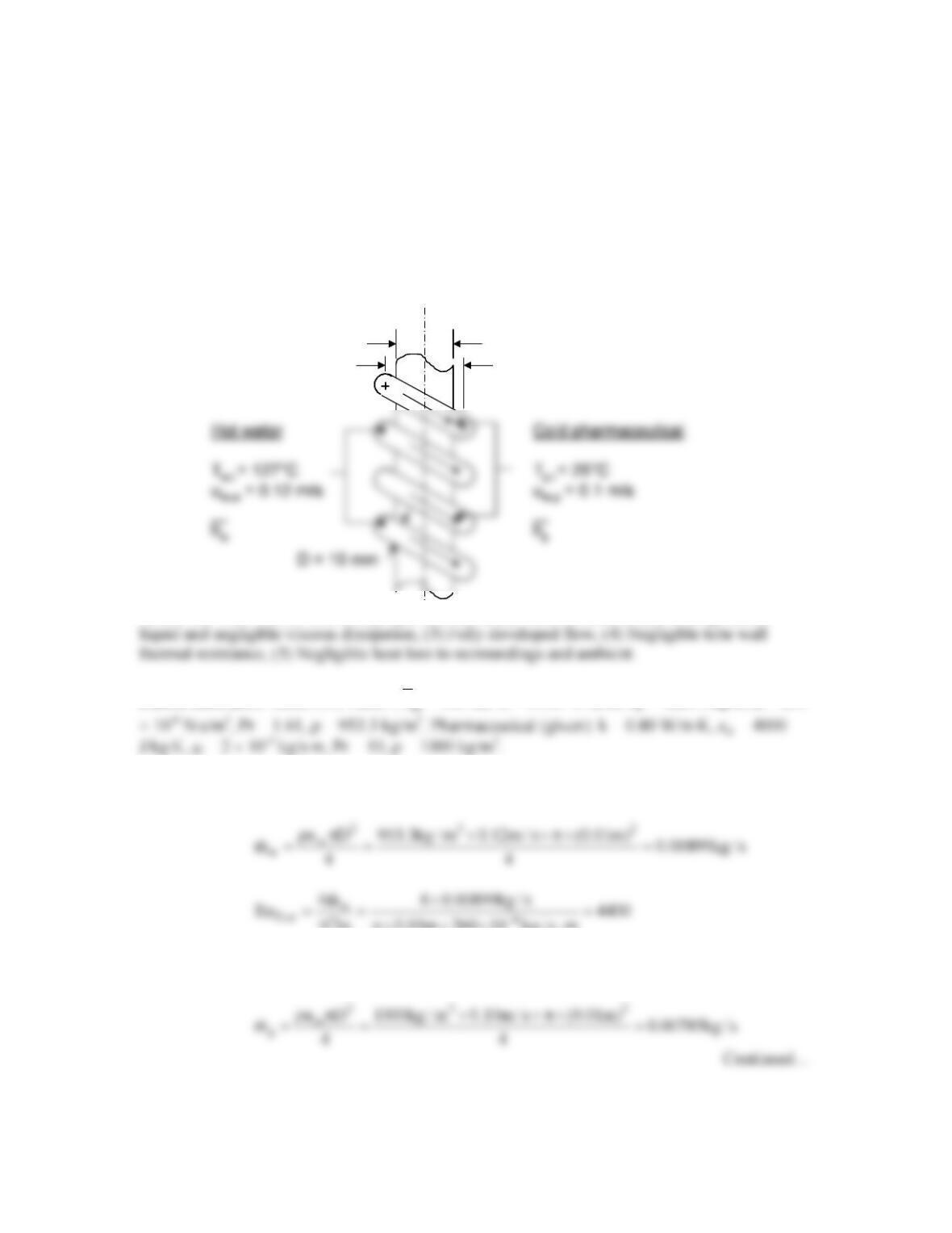
KNOWN: Inlet temperatures and flow rates of a pharmaceutical product and pressurized water,
tube diameter, coil diameter and number of coils.
FIND: (a) The outlet temperature of the pharmaceutical product, (b) The variation of the
pharmaceutical outlet temperature with the pressurized water flow rate.
SCHEMATIC:
ASSUMPTIONS: (1) Constant properties and steady-state conditions, (2) Incompressible
PROPERTIES: Table A.6, water: (
T
= 380 K): k = 0.683 W/m⋅K, cp = 4226 J/kg⋅K, µ = 260
ANALYSIS: For the water,
D0.01m 260 10 kg / s m
pµ p× × × ⋅
For the pharmaceutical,
D
r
= 40 mm
C
D
r
= 40 mm
C
PROBLEM 8.81 (Cont.)
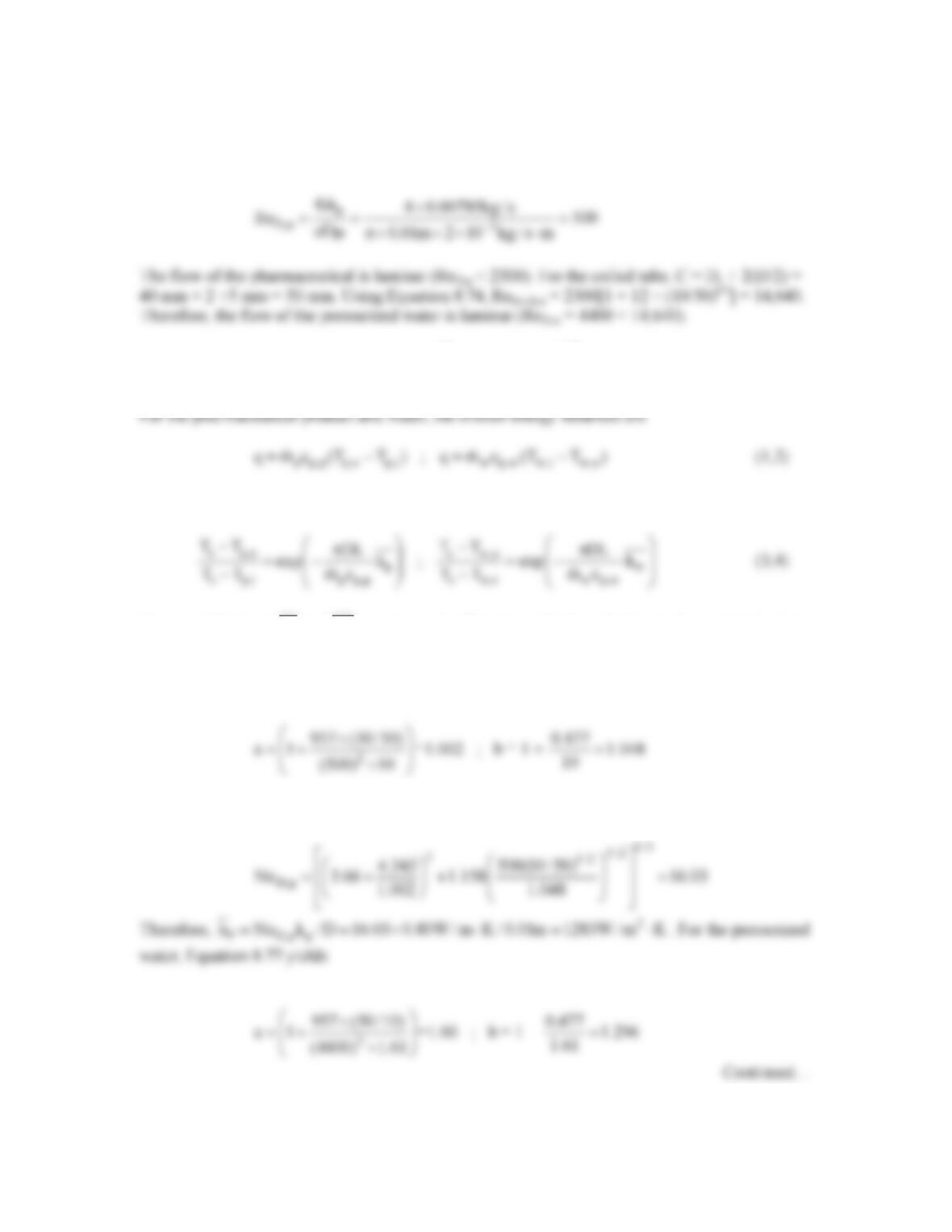
For the pharmaceutical product, ReD,p(D/C)1/2 = 500 × (10/50)1/2 = 223, while for the water
ReD,w(D/C)1/2 = 4400 × (10/50)1/2 = 1967. For each tube, C/D = 50/10 = 5 > 3.
For the pharmaceutical and water, Equation 8.42 is
Once we determine
pw
h and h ,
we may solve Equations (1) through (4) simultaneously for four
unknowns: q, Tp,o, Tw,o and Ts. We will use Equation 8.76, but be aware that we are using the
correlation outside of its recommended range of applicability for the water. For the
pharmaceutical product, Equation 8.77 yields
Therefore, Equation 8.76 becomes
PROBLEM 8.81 (Cont.)
Proceeding as before, we find
2
D,w w
Nu 41.01,h 2801W / m K= = ⋅
. The tube length is L = N × p
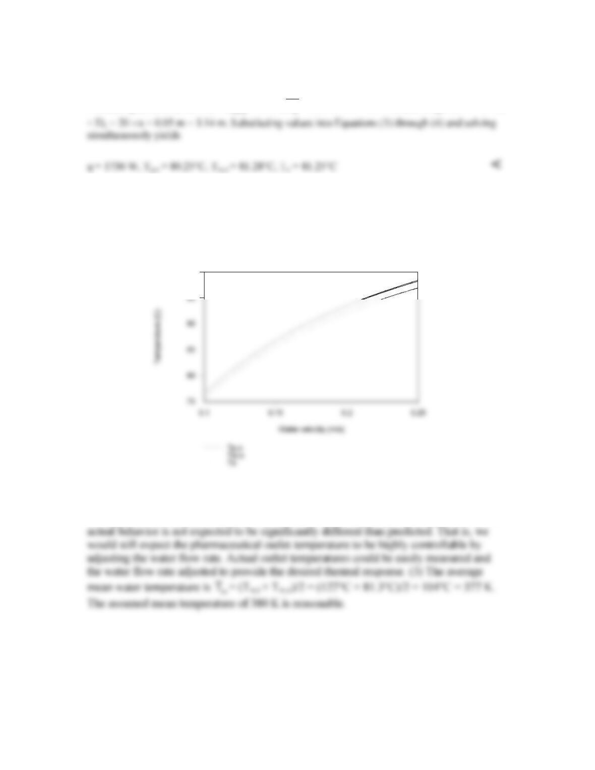
(b) The dependence of the pharmaceutical outlet temperature on the water velocity is shown in
the graph below. Note that the pharmaceutical product’s outlet temperature can be controlled
accurately by modifying the water flow rate.
Temperature vs Water Velocity
100
COMMENTS: (1) The pharmaceutical outlet temperature will be relatively uniform
across the diameter of the tube due to mixing associated with secondary flow. (2)
Although we have applied Equation 8.76 outside of its range of general applicability, the
PROBLEM 8.82
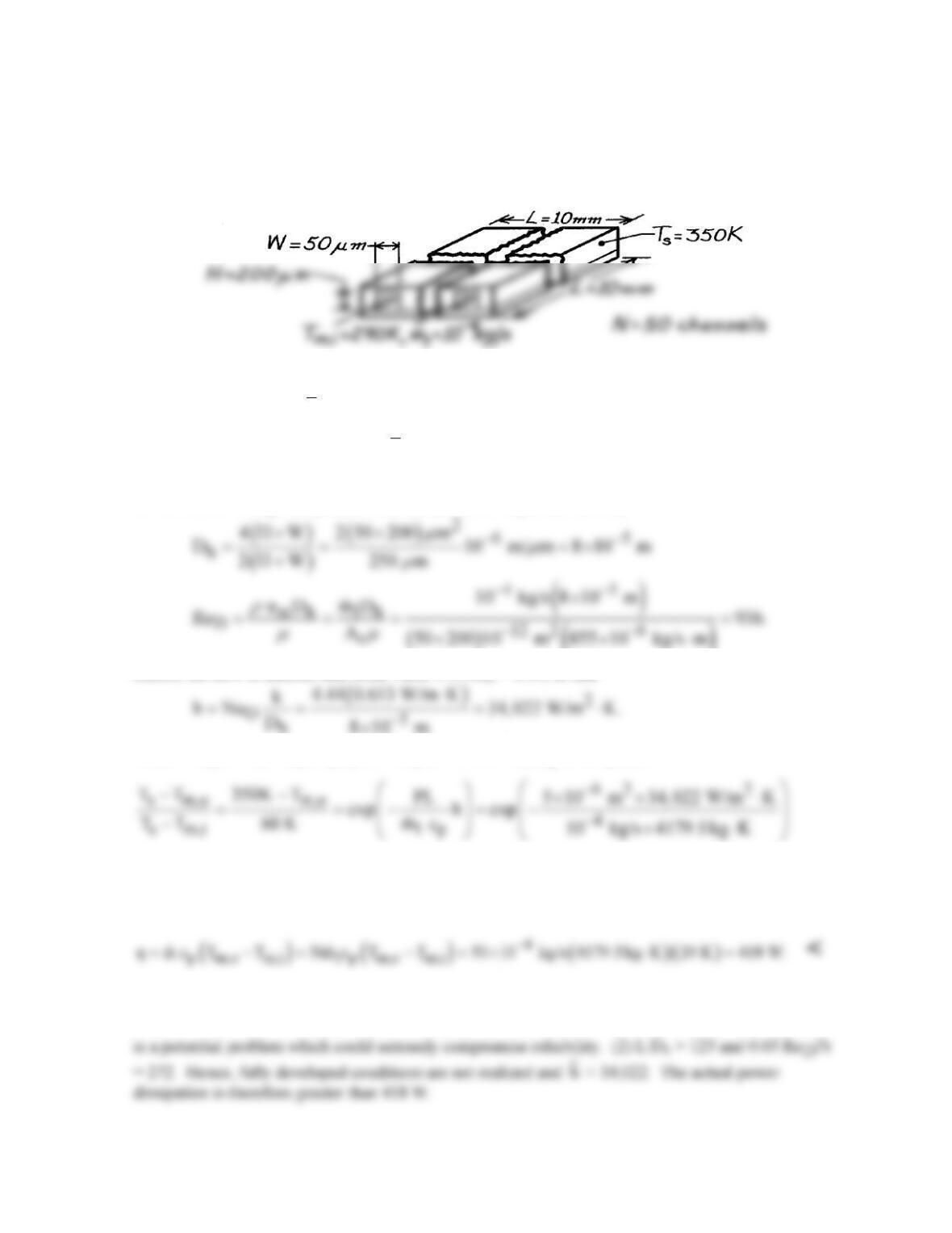
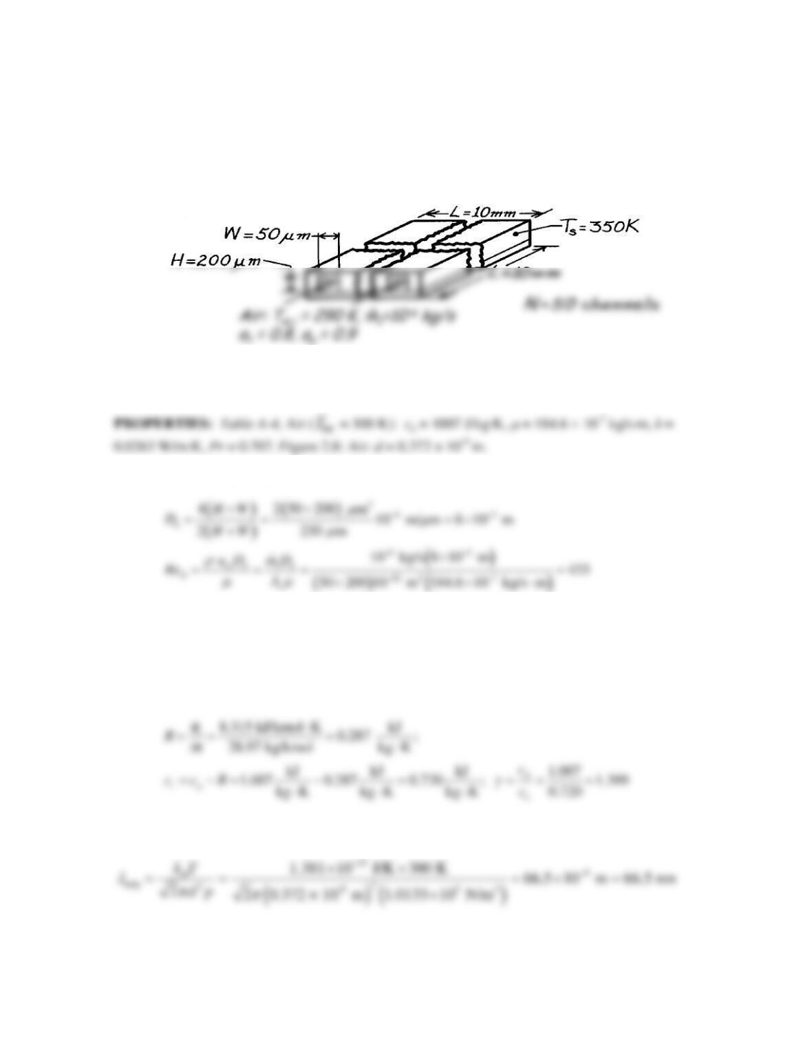
KNOWN: Chip and cooling channel dimensions. Channel flowrate and inlet temperature. Chip
temperature.
FIND: Water outlet temperature and chip power.
SCHEMATIC:
ASSUMPTIONS: (1) Incompressible liquid with negligible viscous dissipation, (2) Uniform channel
surface temperature, (3)
m
T
= 300 K, (4) Fully developed flow.
PROPERTIES: Table A-6, Water (
m
T
= 300 K): cp = 4179 J/kg⋅K, µ = 855 × 10–6 kg/s⋅m, k =
0.613 W/m⋅K, Pr = 5.83.
ANALYSIS: Using the hydraulic diameter, find the Reynolds number,
()
Hence, the flow is laminar and, from Table 8.1, NuD = 4.44, so that
With P = 2(H + W) = 2(250 µm) 10-6 m/µm = 5 ×10⁻⁴ m, Eq. 8.41b yields
( )
m,o
T 350K 60 K exp 0.407 310 K.=− −=
<
Hence, from Eq. 8.34,
COMMENTS: (1) The chip heat flux of 418 W/cm2 is extremely large and the method provides a
very efficient means of heat removal from high power chips. However, clogging of the microchannels
PROBLEM 8.83
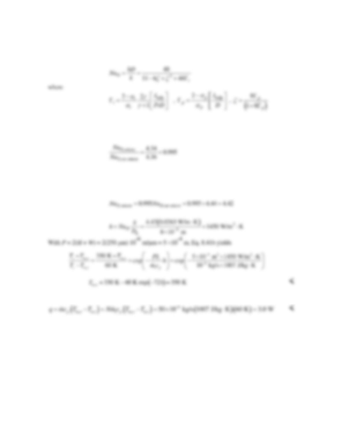
KNOWN: Chip and cooling channel dimensions. Air flow rate and inlet temperature. Thermal and
momentum accommodation coefficients. Chip temperature. Nusselt number is affected due to
microscale effects in same proportion as for a uniform heat flux condition in a circular pipe.
FIND: Air outlet temperature and chip power.
SCHEMATIC:
ASSUMPTIONS: (1) Incompressible fluid with negligible viscous dissipation, (2) Uniform channel
surface temperature, (3) Fully developed flow, (4) In accounting for microscale effects, D can be
replaced by Dh.
ANALYSIS: Using the hydraulic diameter, find the Reynolds number,
Hence, the flow is laminar and, from Table 8.1, NuD = 4.44 without taking microscale effects into
account.
Next, we consider microscale effects. The ideal gas constant, specific heat at constant volume, and
ratio of specific heats are:
From Equation 2.11 the mean free path of air is
Continued…
PROBLEM 8.83 (Cont.)
From Equation 8.78, the Nusselt number for constant heat flux in a circular pipe, accounting for
microscale effects, may be expressed as
Assuming D can be replaced by Dh, we find
0.00206,
t
Γ=
0.00102,
p
Γ=
0.00806,
ζ
=
and NuD =
4.34. The ratio of Nusselt number with and without microscale effects is:
For these particular conditions, the Nusselt number is not strongly affected by microscale phenomena.
The Nusselt number without microscale effects in the rectangular channel with constant wall
temperature was found in Table 8.1 to be NuD = 4.44. Therefore,
Hence, from Eq. 8.34,
COMMENTS: (1) The chip heat flux of 3 W/cm2 is not very large. Under the specified conditions,
the heat transfer performance is sufficient to bring the air to the surface temperature by the end of the
channel, so poor heat transfer is not the issue. The problem is the low mass flow rate of air. A higher
mass flow rate could be used, provided pumping power does not become too large. (2) The
hydrodynamic and thermal entry lengths are 0.05ReDDh = 1.7 mm and 0.05ReDDhPr = 1.2 mm. Hence,
the assumption of fully developed conditions is appropriate. (3) Microscale effects are modest and in
this case slightly decrease heat transfer. Microscale effects can either increase or decrease heat
transfer depending on the accommodation coefficients and tube diameter (see Problem 8.87).
PROBLEM 8.84
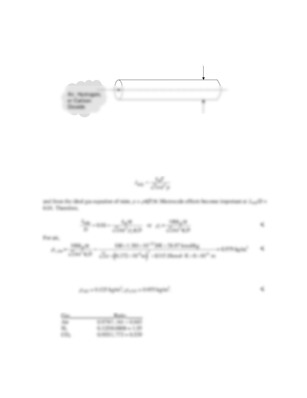
KNOWN: Flow of an ideal gas through a small diameter tube.
FIND: Expression for the transition density, below which microscale effects become important.
Value of the transition density for hydrogen, air and carbon dioxide.
SCHEMATIC:
ASSUMPTIONS: (1) Constant properties, (2) Ideal gas.
PROPERTIES: Figure 2.8 and Table A.4 (p = 1 atm, T = 300 K) Air: M = 28.97 kmol/kg, d = 0.372
nm,
ρ
= 1.161 kg/m3, H2: M = 2.016 kmol/kg, d = 0.274 nm,
ρ
= 0.0808 kg/m3, CO2: M = 44.01
kmol/kg, d = 0.464 nm,
ρ
= 1.773 kg/m3.
ANALYSIS: From Eq. 2.11 the mean free path is
Repeating the calculation for hydrogen and CO2 yields
The ratios of the transition to molecular density at p = 1 atm, T = 300 K, for the three gases are:
COMMENT: Microscale effects could be important, especially for hydrogen at atmospheric pressure
and T = 300 K.
D = 10
µ
m
D = 8
µ
m
PROBLEM 8.85
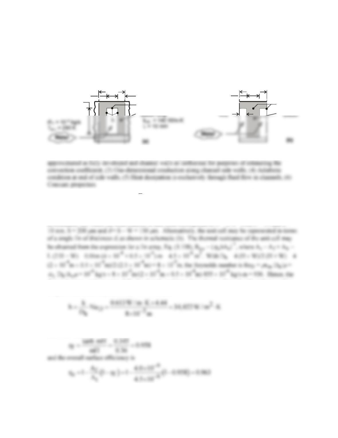
KNOWN: Chip and cooling channel dimensions. Channel flow rate and inlet temperature.
Temperature of chip at base of channel.
FIND: (a) Water outlet temperature and chip power, (b) Effect of channel width and pitch on power
dissipation.
SCHEMATIC:
T
s
= 350 K
H = 200 m
µ
W
δ
/2
δ
S S
T
s
ASSUMPTIONS: (1) Incompressible liquid with negligible viscous dissipation, (2) Flow may be
PROPERTIES: Table A-6, Water (
m
T
= 300K): cp = 4179 J/kg⋅K,
µ
= 855 × 10-6 kg/s⋅m, k = 0.613
W/m⋅K, Pr = 5.83.
ANALYSIS: (a) The channel sidewalls act as fins, and a unit channel/sidewall combination is shown
in schematic (a), where the total number of unit cells corresponds to N = L/S. With N = 50 and L =
flow is laminar, and assuming fully developed conditions throughout a channel with uniform surface
temperature, Table 8.1 yields NuD = 4.44. Hence,
With m = (2h/kch
δ
)1/2 = (68,044 W/m2⋅K/140 W/m⋅K × 1.5 × 10⁻⁴m)1/2 = 1800 m-1 and mH = 0.36,
the fin efficiency is
The thermal resistance of the unit cell is then
Continued …
PROBLEM 8.85 (Cont.)
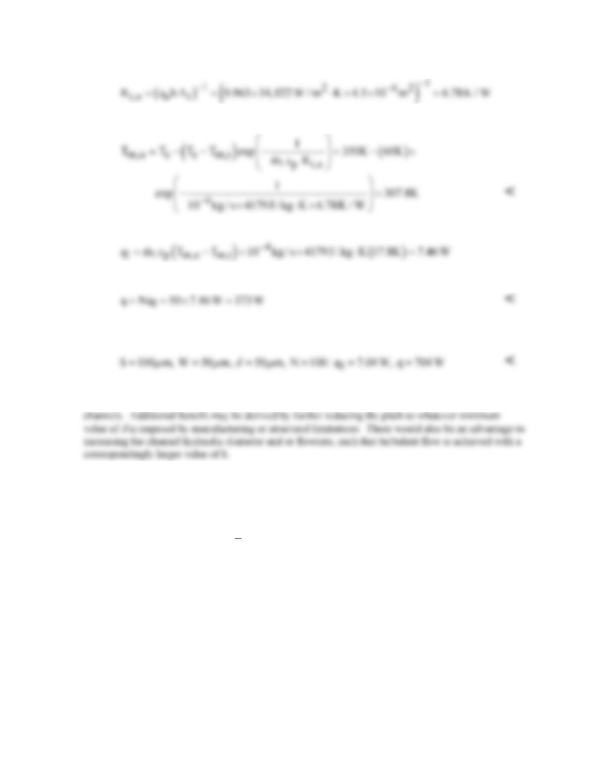
The outlet temperature follows from Eq. (8.45b),
The heat rate per channel is then
and the chip power dissipation is
(b) The foregoing result indicates significant heat transfer from the channel side walls due to the large
value of
h
f. If the pitch is reduced by a factor of 2 (S = 100
µ
m), we obtain
Hence, although there is a reduction in
h
f due to the reduction in
δ
(
h
f = 0.89) and therefore a slight
reduction in the value of ql, the effect is more than compensated by the increase in the number of
COMMENTS: (1) Because electronic devices fail by contact with a polar fluid such as water, great
care would have to be taken to hermetically seal the devices from the coolant channels. In lieu of
water, a dielectric fluid could be used, thereby permitting contact between the fluid and the
electronics. However, all such fluids, such as air, are less effective as coolants. (2) With L/Dh = 125
and L/Dh)fd ≈ 0.05 ReD Pr = 273, fully developed flow is not achieved and the value of h = hfd
underestimates the actual value of
h
in the channel. The coefficient is also underestimated by using a
Nusselt number that presumes heat transfer from all four (rather than three) surfaces of a channel.
PROBLEM 8.86
KNOWN: Temperature and pressure of a gas flowing in a circular tube.
FIND: The critical tube diameter, Dc, below which incompressible turbulent flow cannot exist for (a)
air (b) CO2, and (c) He.
SCHEMATIC:
ASSUMPTIONS: (1) Ideal gas behavior. (2) Fully-developed flow.
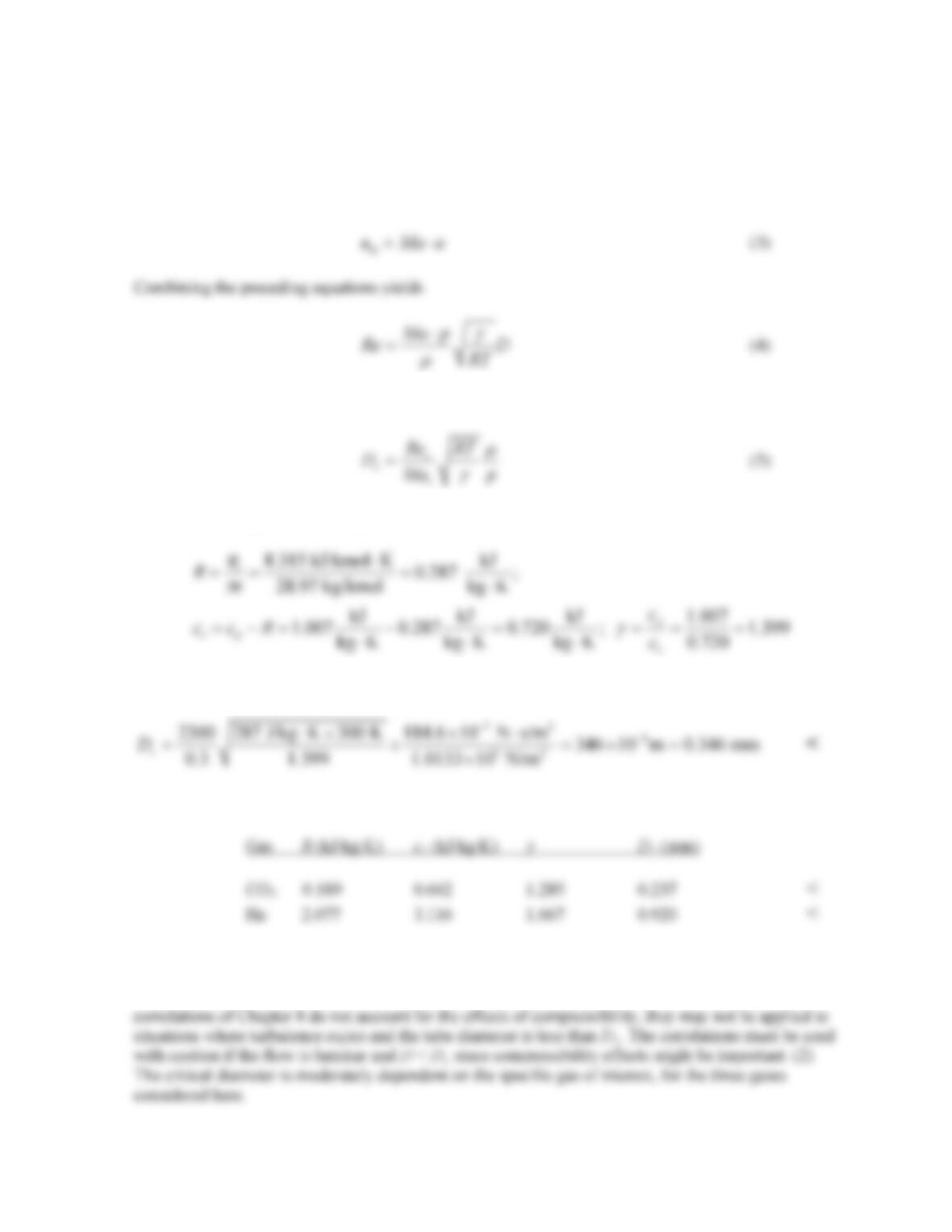
ANALYSIS: The relationship ReD,c = umD/
ν
≈ 2300 may be plotted on a log-log scale, as shown in
the figure below. Laminar flow occurs to the left of the sloped line, while turbulent flow occurs to the
(a) From the ideal gas equation of state,
ρ
= p/RT (1)
and from Section 6.4.2 the speed of sound is
PROBLEM 8.86 (Cont.)
where
g
≡ cp/cv is the ratio of specific heats. The mean velocity may be related to the Mach number,
Ma, and is
Specifying Re = Rec and Ma = Mac leads to the following expression for the critical tube diameter
For air, the ideal gas constant, specific heat at constant volume, and ratio of specific heats are
Therefore,
(b,c) The calculations may be repeated for CO2 and He, yielding the following results.
COMMENTS: (1) Below the critical diameter, Dc, the effects of compressibility must always be
accounted for if the flow is turbulent, and are often important if the flow is laminar. Because the
PROBLEM 8.87
KNOWN: Temperature and pressure of air flowing in a circular tube of known diameter. Thermal
and momentum accommodation coefficients. Fully developed laminar flow with constant heat flux.
SCHEMATIC:
ASSUMPTIONS: (1) Ideal gas behavior. (2) Fully–developed laminar flow.
ANALYSIS: The ideal gas constant, specific heat at constant volume, and ratio of specific heats are:
From Equation 2.11 the mean free path of air is
From Equation 8.78, the Nusselt number may be expressed as
Air
Unknown material
PROBLEM 8.87 (Cont.)
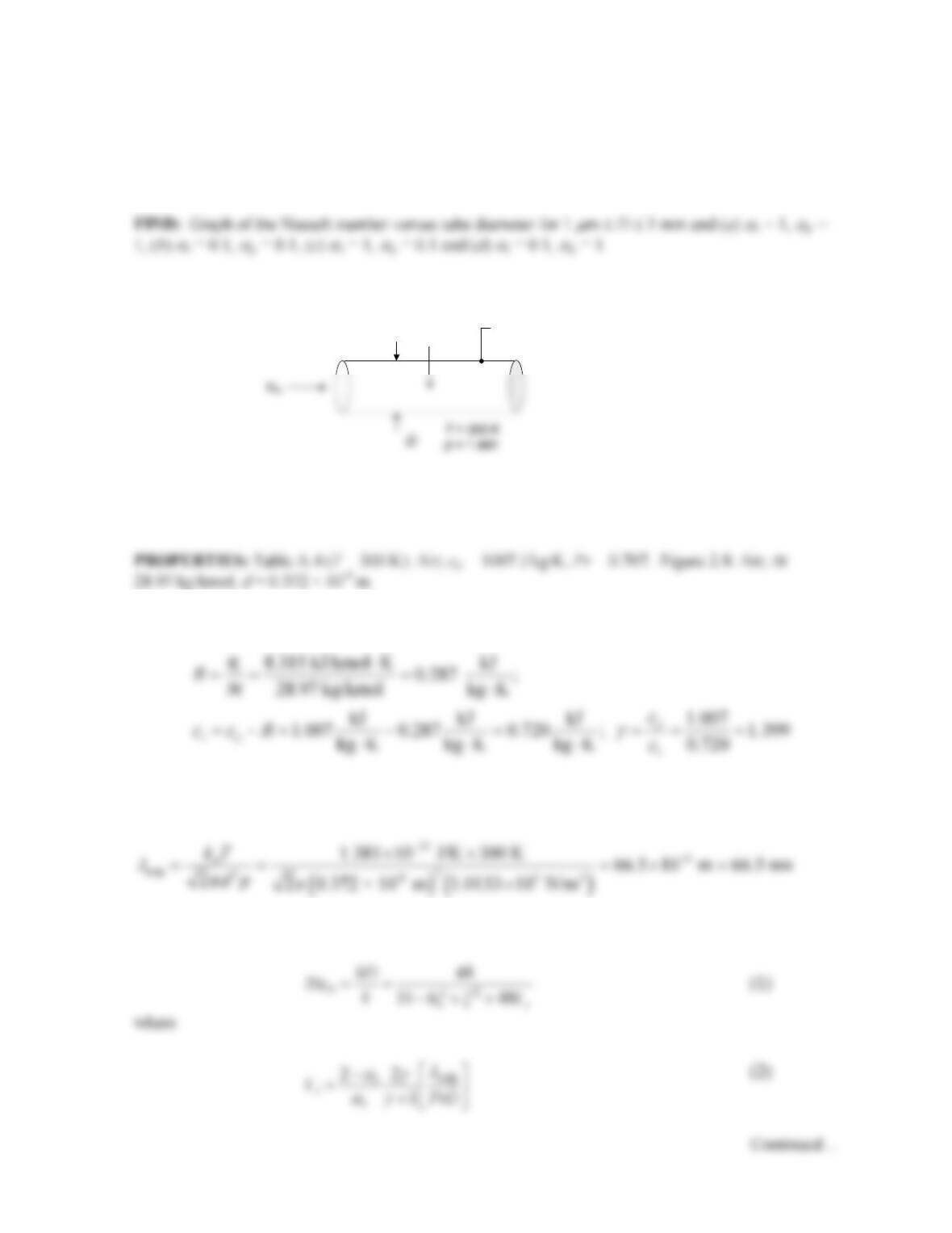
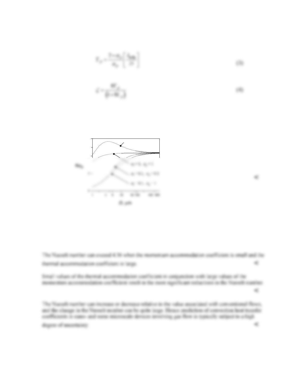
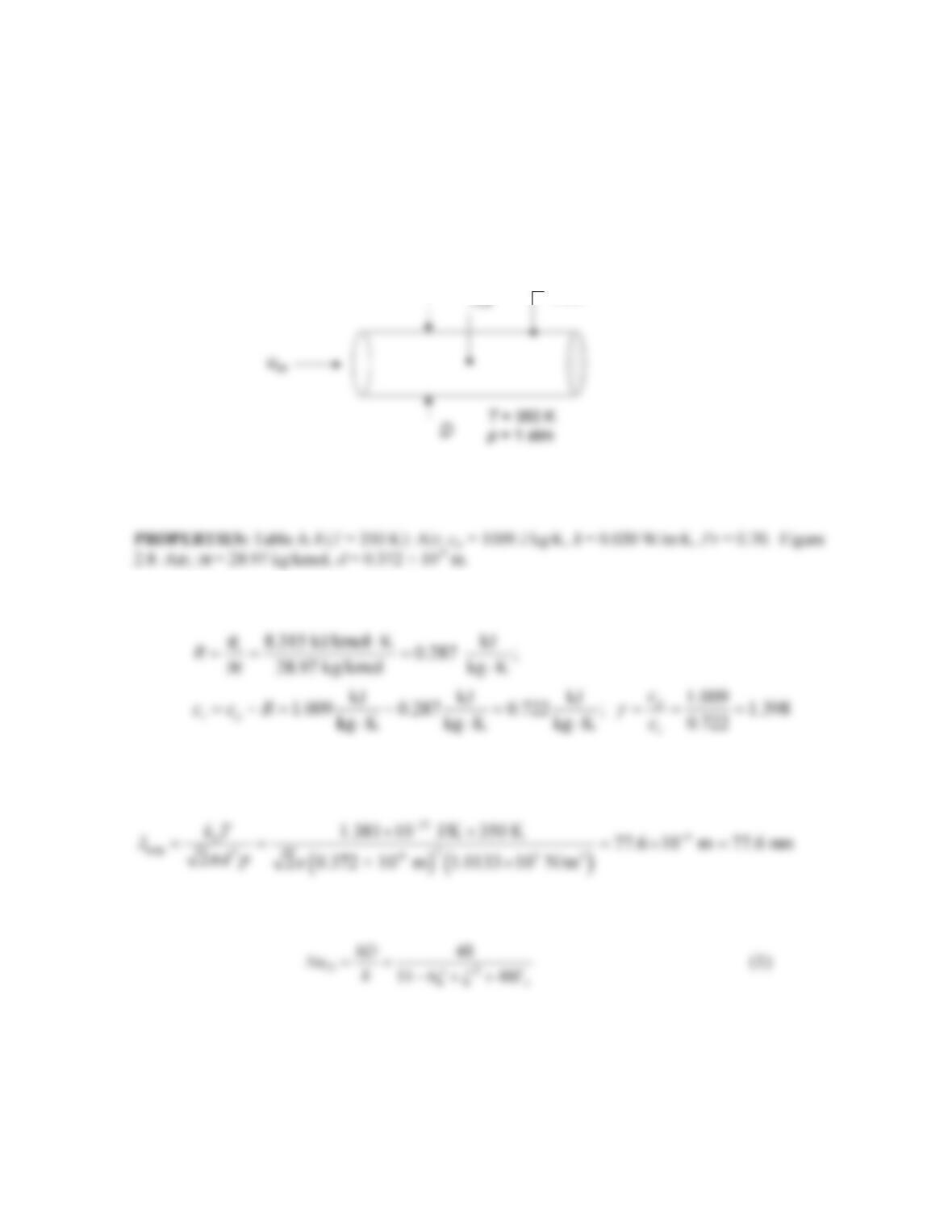
Equations 1 through 4 may be combined to yield the following graph that shows the variation of the
Nusselt number over the tube diameter range 1
µ
m ≤ D ≤ 1000
µ
m.
The accommodation coefficients begin to influence the Nusselt number (and hence the convection heat
transfer coefficient) at diameters less than approximately 400
µ
m. <
The Nusselt number is least sensitive to changes in the tube diameter for
α
t =
α
p = 1. <
Comment: Thermal accommodation coefficients can be of very small value, as discussed in Chapter
3.
alphat = alphap = 1
4
6
alphat = alphap = 0.1
4
6
alphat = 0.1 alphap = 1
4
6
alphat = 1 alphap = 0.1
4
6
α
t= 1,
α
p= 0.1
alphat = alphap = 1
4
6
alphat = alphap = 0.1
4
6
alphat = 0.1 alphap = 1
4
6
alphat = 1 alphap = 0.1
4
6
α
t= 1,
α
p= 0.1
PROBLEM 8.88
KNOWN: Temperature and pressure of a gas flowing in a circular tube of known diameter with
constant surface heat flux. Thermal and momentum accommodation coefficients. Fully developed
laminar flow.
FIND: Graph of the Nusselt number for tube diameters of 1
µ
m ≤ D ≤ 1 mm.
SCHEMATIC:
ASSUMPTIONS: (1) Ideal gas behavior. (2) Fully–developed laminar flow.
ANALYSIS: The ideal gas constant, specific heat at constant volume, and ratio of specific heats are:
From Equation 2.11 the mean free path of air is
From Equation 8.78 the Nusselt number may be expressed as
where
Continued…
Steel
PROBLEM 8.88 (Cont.)
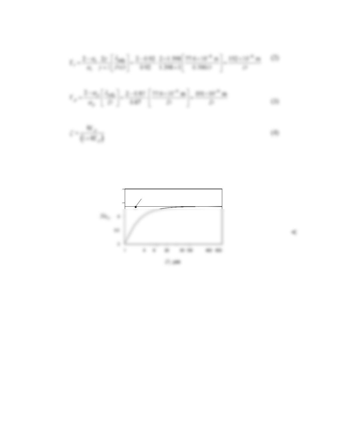
Equations 1 through 4 may be combined to yield the following graph that shows the variation of the
Nusselt number over the tube diameter range 1
µ
m ≤ D ≤ 1000
µ
m.
COMMENTS: (1) The Nusselt number begins to be affected by the tube dimension at a tube
diameter of D ≈ 100 µm. (2) Equation 8.78 is associated with constant heat flux conditions. We would
expect a similar reduction in Nusselt numbers for constant temperature wall conditions.
4.5
5
Nu
D
= 4.36
PROBLEM 8.89
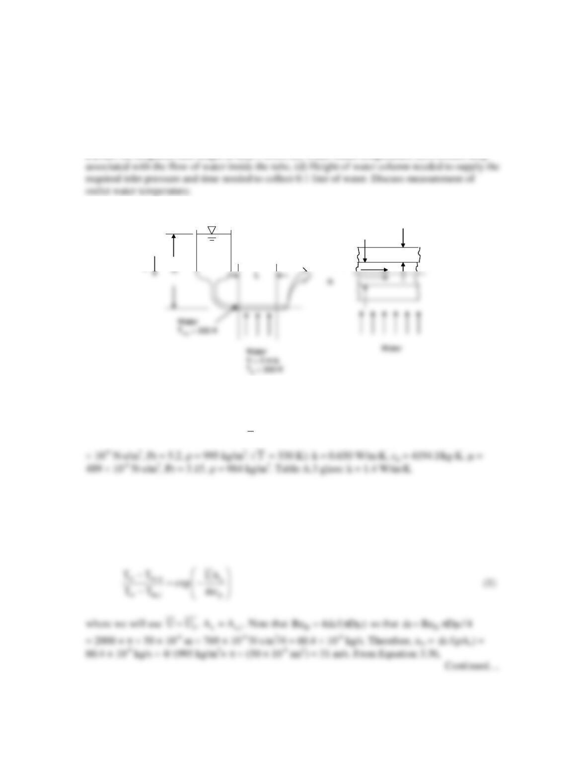
KNOWN: Inner diameter of microscale tube, wall thickness of tube, temperature of water inside
the tube, and temperature of water in cross flow over the tube.
FIND: (a) Required tube length at ReD = 2000, (b) Water outlet temperature, (c) Pressure drop
SCHEMATIC:
g
d = 50 µmt = 1 mm
Water
g
d = 50 µmt = 1 mm
d = 50 µmt = 1 mm
Water
Water
ASSUMPTIONS: (1) Constant properties and steady-state conditions, (2) Incompressible
liquid and negligible viscous dissipation, (3) Negligible microscale or nanoscale effects.
PROPERTIES: Table A.6, water: (
m
T
= 305 K): k = 0.620 W/m⋅K, cp = 4178 J/kg⋅K, µ = 769
ANALYSIS: (a) At ReD = 2000, Equation 8.3 yields xfd,h = 0.05ReDPrD = 0.05 × 2000 × 5.2 ×
50 × 10-6 m = 26 × 10-3 m. Therefore, L = 2xfd,h = 2 × 26 × 10-3 m = 52 × 10-6 m = 52 mm. <
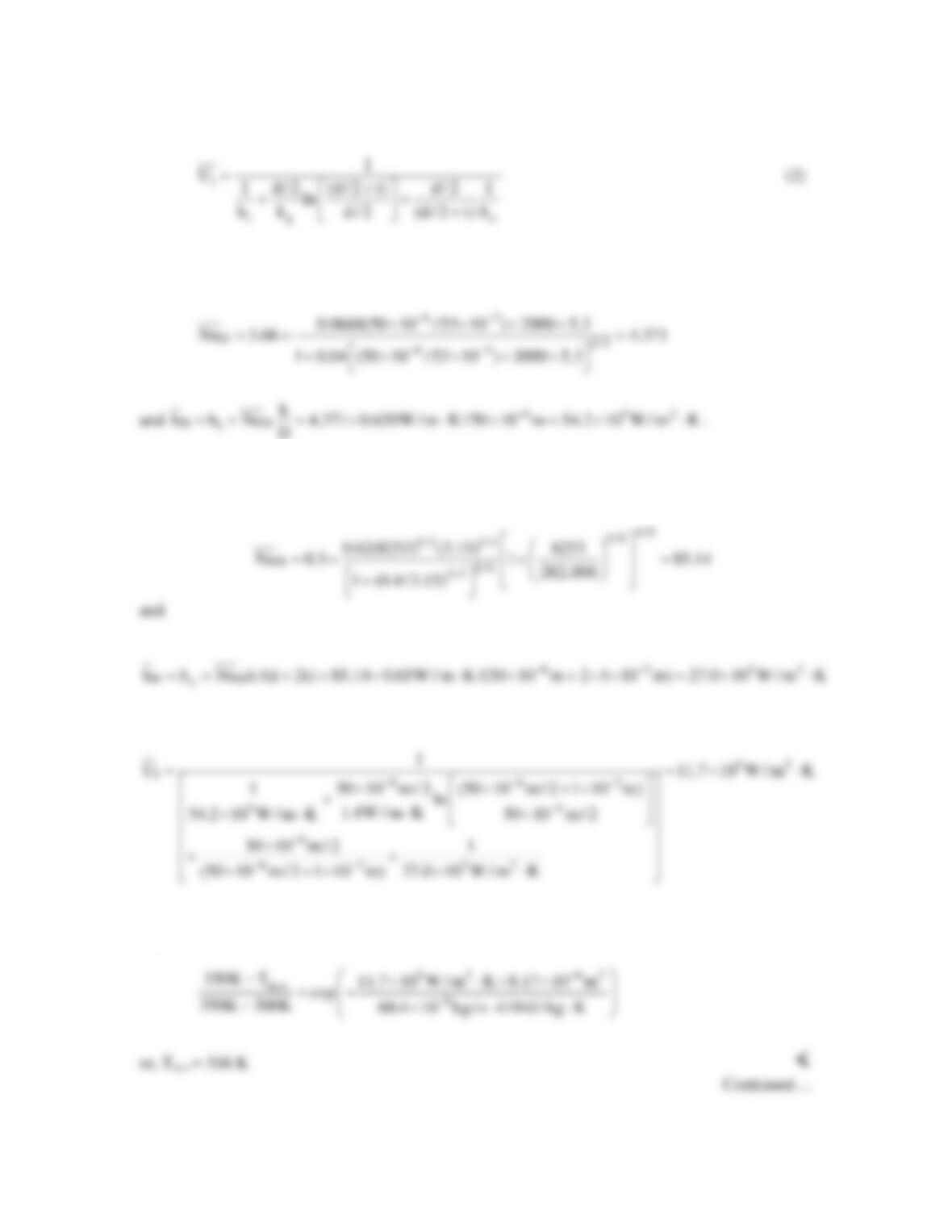
(b) Equation 8.45a is
PROBLEM 8.89 (Cont.)
As,i = pdL = p × 50 × 10-6 m × 52 × 10-3 m = 8.17 × 10⁻⁶ m2. From Equation 8.57,
D
For the cross flow of water over the tube, ReD = VDρ/µ = 2 m/s × (50 × 10-6 m + 2 × 1 × 10-3
m)(984 kg/m3)/489 × 10-6 N∙s/m2 = 8253. From Equation 7.54,
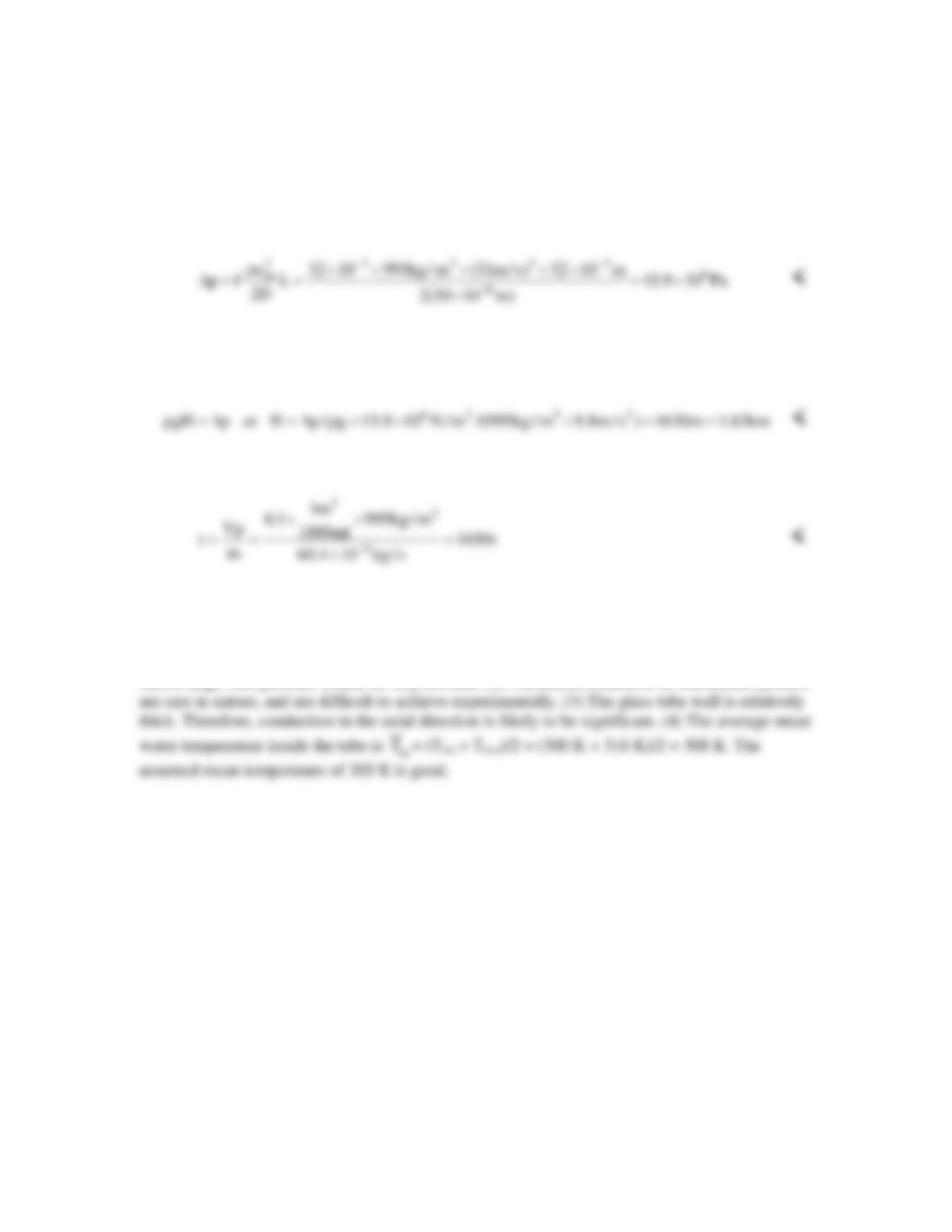
Therefore,
Equation (1) becomes
PROBLEM 8.89 (Cont.)
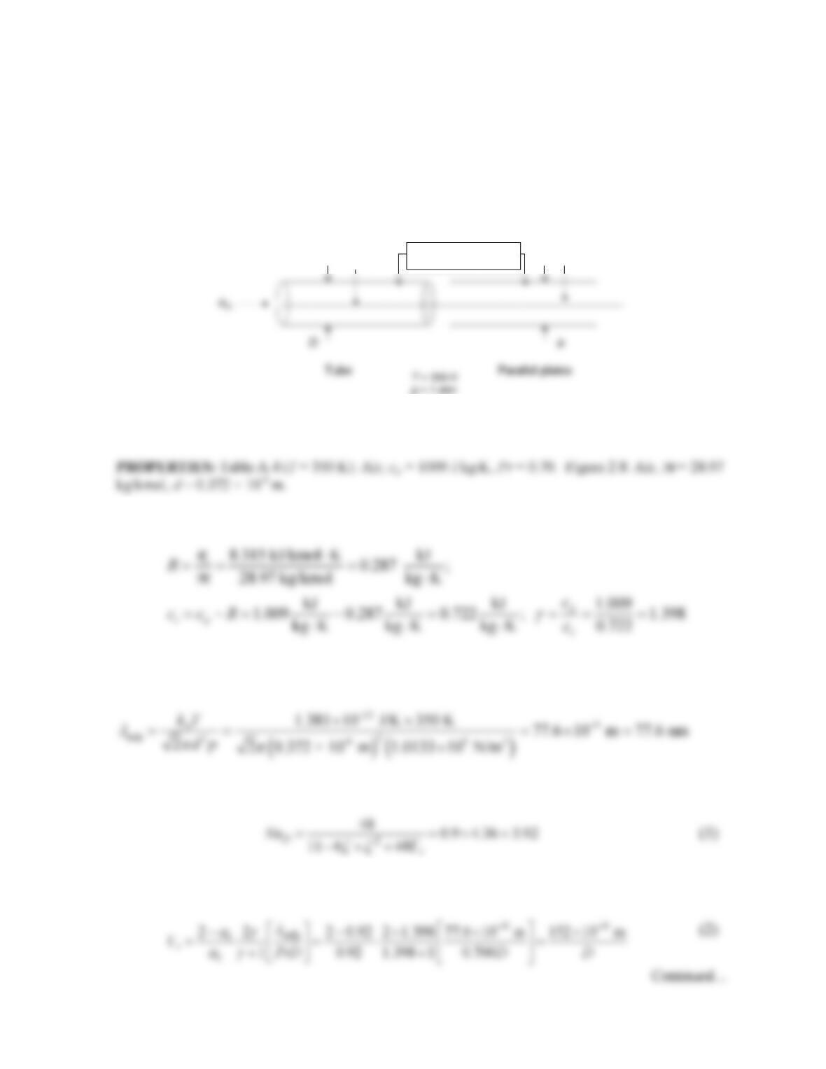
(c) For laminar flow, Equation 8.19 yields f = 64/ReD = 64/2000 = 32 × 10-3. Equation 8.22a
yields
(d) The pressure generated by the water column must offset the pressure drop in the tube.
Therefore,
The time required for a particular volume of water to flow through the system is
COMMENTS: (1) Microscale experimentation is often very difficult to perform. In addition to
the difficulty in measuring the water outlet temperature, establishing a constant flow rate with
such a large inlet pressure would be very difficult. (2) Turbulent conditions in microscale systems
PROBLEM 8.90
KNOWN: Temperature and pressure of air flowing in a circular tube or between parallel plates.
Thermal and momentum accommodation coefficients.
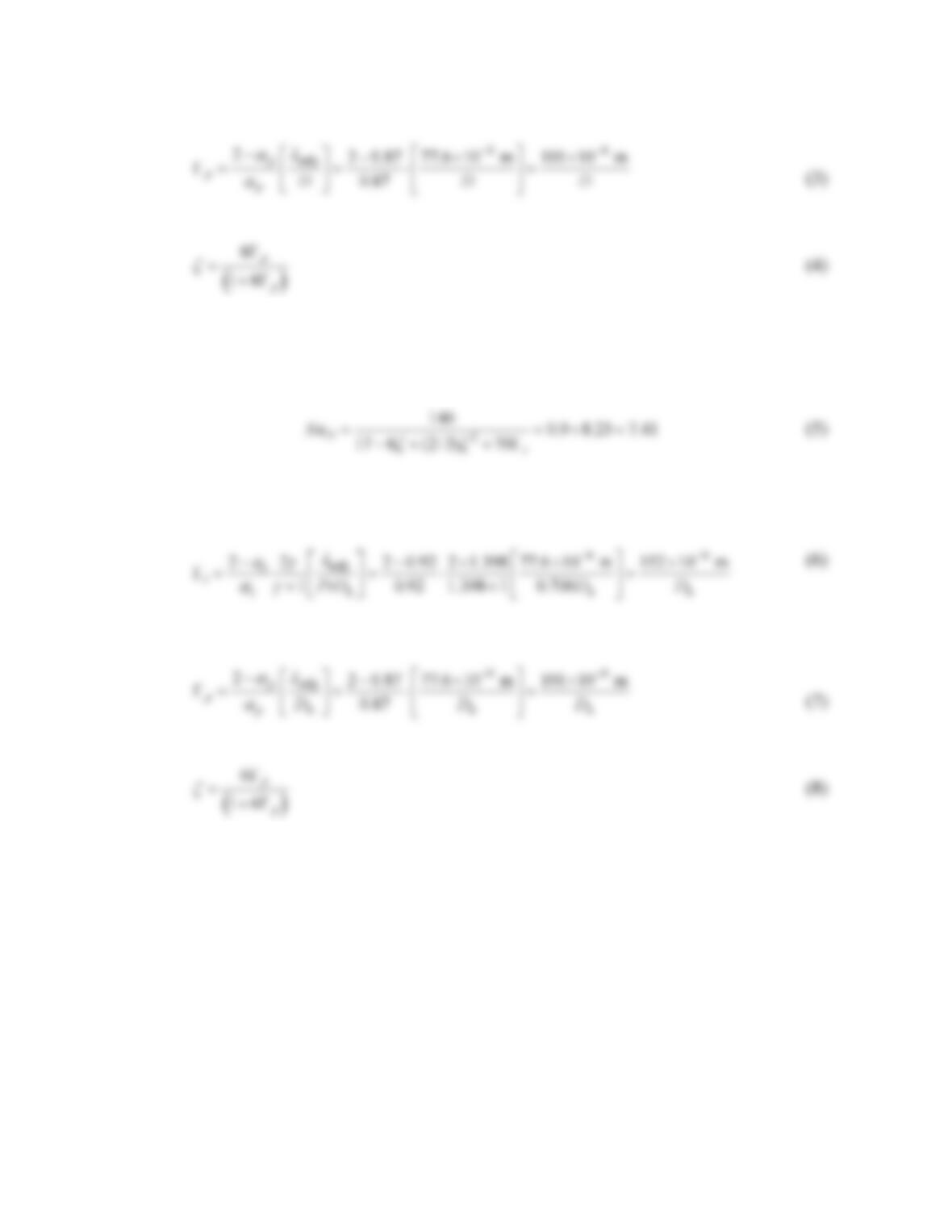
FIND: Tube diameter D and plate spacing a that correspond to a 10 percent reduction in the Nusselt
number.
SCHEMATIC:
ASSUMPTIONS: (1) Ideal gas behavior. (2) Fully–developed laminar flow.
ANALYSIS: The ideal gas constant, specific heat at constant volume, and ratio of specific heats are:
From Equation 2.11 the mean free path of air is
From Equation 8.78 the Nusselt number for the tube may be expressed as
where
Air
Air
α
t= 0.92,
α
p= 0.87
PROBLEM 8.90 (Cont.)
Equations 1 through 4 may be solved by trial-and-error to yield D = 2.94 × 10⁻⁶ m = 2.94 µm. <
From Equation 8.79 the Nusselt number for the parallel plate configuration may be expressed as
where
Equations 5 through 8 may be solved by trial-and-error to yield Dh = 3.97 × 10⁻⁶ m = 3.97 µm. The
plate spacing a = Dh/2 = 3.97 µm/2 = 1.99 µm. <
COMMENTS: The tube diameter and plate spacing required to reduce the Nusselt number by 10
percent are quite small. In situations involving characteristic dimensions that are not extremely small,
the effect of the molecule-wall interaction can typically be neglected.