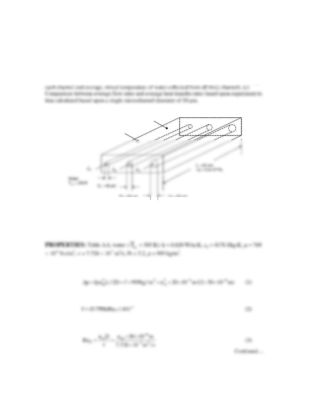
PROBLEM 8.91
KNOWN: Diameters and length of three microchannels machined in a copper block. Inlet
temperature of water flowing through the channels, copper block temperature, pressure difference
from inlet to outlet of the channels.
FIND: (a) Mass flow rate and outlet temperature in each channel, (b) Average flow rate through
SCHEMATIC:
D
3
= 55 mmD
2
= 50 mm
T
cu
= 310 K
Copper block
D
3
= 55 mmD
2
= 50 mm
T
cu
= 310 K
Copper block
ASSUMPTIONS: (1) Constant properties and steady-state conditions, (2) Incompressible
liquid and negligible viscous dissipation, (3) Negligible microscale or nanoscale effects, (4)
Negligible entrance or exit losses in the microchannels, (5) Fully developed flow for purposes of
calculating the mass flow rate in each channel, (6) Isothermal copper block.
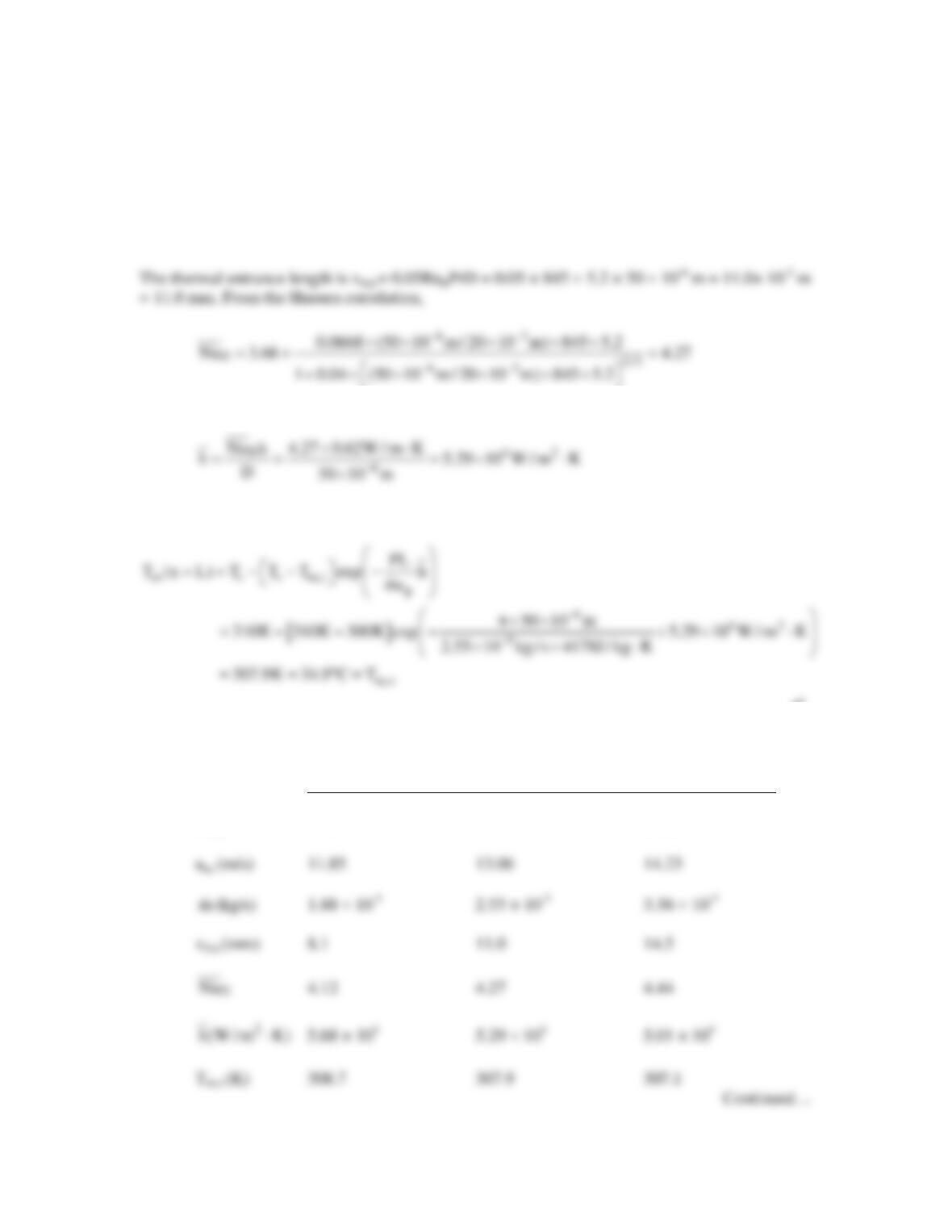
ANALYSIS: (a) For the D = 50 mm channel, from Equation 8.22a,
where the friction factor may be evaluated using the Petukhov expression,
The Reynolds number may be expressed as
PROBLEM 8.91 (Cont.)
Simultaneous solution of Equations (1) through (3) yields, for the D = 50 mm channel, ReD = 845,
um = 13.06 m/s. The mass flow rate is
2 3 62 5
m
m u D / 4 995kg / m 13.06m / s (50 10 m) / 4 2.55 10 kg / s
−−
=r π = × ×π× × = ×
<
Hence,
From Equation 8.41b,
<
Results for the three different channels are shown in the table below. <
D = 45 mm (case 1) D = 50 mm (case 2) D = 55 mm (case 3)
ReD 690 845 1012
PROBLEM 8.91 (Cont.)
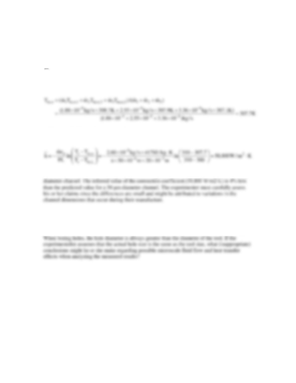
(b) The average mass flow rate is
555 5
123
m (m m m ) / 3 (1.88 10 2.55 10 3.36 10 )kg / s / 3 2.60 10 kg / s
−−− −
=++ = ×+×+× =×
<
The average, mixed outlet temperature is
(c) Equation 8.41b may be re–arranged to
Thus, the inferred value of the mass flow rate is 2% greater than the predicted value for a 50 mm
COMMENTS: (1) Experimentation at the microscale is challenging. Misinterpretation of the
experimental results might occur unless the experimental system is designed very carefully. For
example, the diameters of the channels might need to be measured after their manufacture. (2)
PROBLEM 8.92
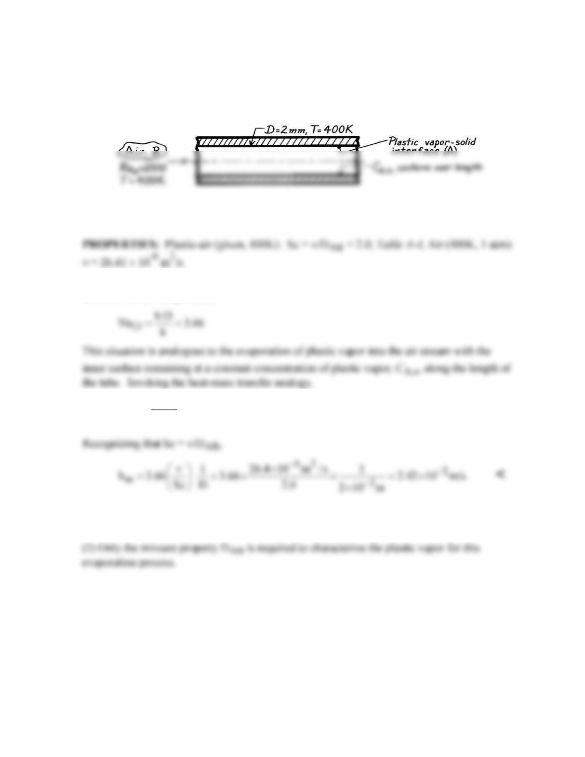
KNOWN: Air flow through a plastic tube in which evaporation occurs.
FIND: Convection mass transfer coefficient, hm.
SCHEMATIC:
ASSUMPTIONS: (1) Steady-state conditions, (2) Constant properties, (3) Heat-mass
transfer analogy applicable, (4) Fully-developed flow and mass transfer conditions.
ANALYSIS: For fully-developed flow and thermal conditions with laminar flow and a
uniform surface temperature,
m
DAB
hD
Sh 3.66.
D
= =
COMMENTS: (1) The heat–mass transfer analogy requires that the vapor (A) have a
negligible effect on the flow. Hence, the flow is that of air (B) and ν = νB.
PROBLEM 8.93
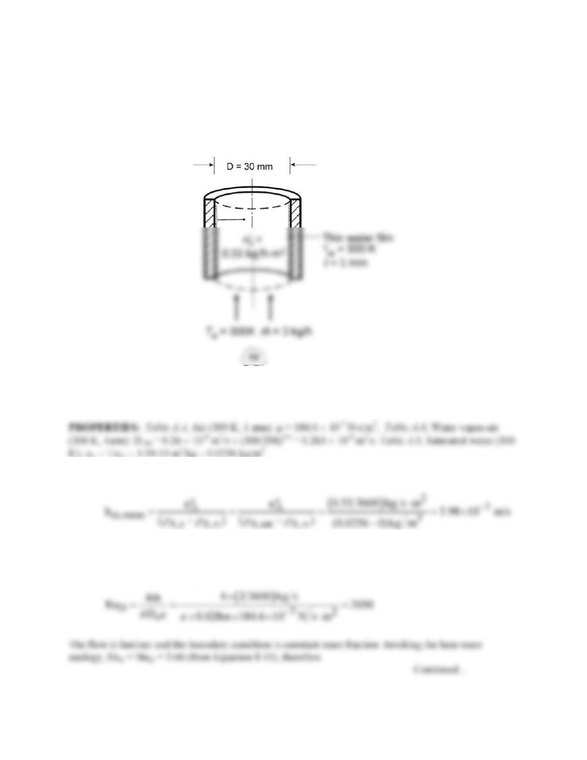
KNOWN: Temperature and flow rate of dry air passing upward through a tube having a rippled water
film flowing downward on its inside surface. Temperature and thickness of film. Tube diameter.
Evaporation rate.
FIND: Percentage change in mass transfer coefficient relative to a smooth, stationary water film.
SCHEMATIC:
ASSUMPTIONS: (1) Steady-state conditions, (2) Constant properties, (3) Heat-mass analogy
applicable, (4) Air is saturated with water at the air–water interface, and (5) Negligible water vapor in the
air stream.
K): rg = 1/υg = 1/39.13 m3/kg = 0.0256 kg/m3.
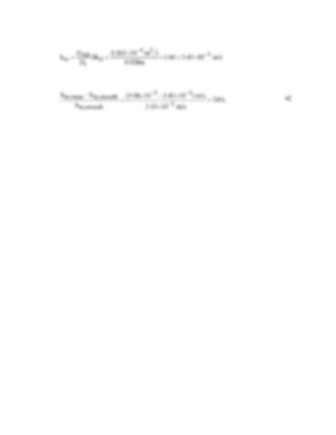
ANALYSIS: We begin by calculating the mass transfer coefficient from the measured evaporation rate:
Next we calculate the mass transfer coefficient for evaporation of water into air for fully developed flow
with a smooth interface. The diameter of the air flow is reduced by the presence of the water film, that is,
Di = D – 2t = 28 mm. The Reynolds number is:
PROBLEM 8.93 (Cont.)
The percentage change in the mass transfer coefficient is:
COMMENTS: (1) The heat–mass analogy requires that the evaporation of water vapor have negligible
effect on the velocity boundary layer. (2) It is important to recognize that the vapor is species (A) and
the air species (B). Furthermore, the properties of the mixture of air and water vapor are approximated as
the properties of pure air, specifically m = mB.
PROBLEM 8.94
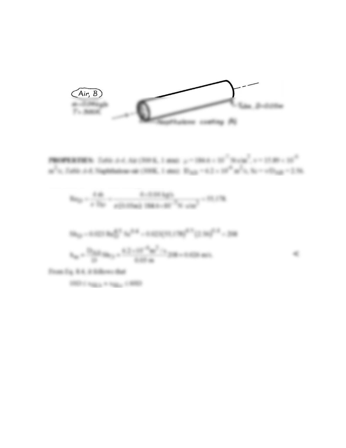
KNOWN: Temperature and flow rate of air in a tube with a naphthalene coated inner surface.
FIND: Convection mass transfer coefficient under fully developed conditions and velocity
and concentration entry lengths.
SCHEMATIC:
ASSUMPTIONS: (1) Heat and mass transfer analogy is applicable, (2) Uniform vapor
concentration along inner surface.
ANALYSIS: For air flow through the tube,
Hence the flow is turbulent and from Eq. 8.88,
or
fd,h fd,c
0.5 m x x 3 m.≤≈≤
<
An entry length of 0.5 m is assumed.
COMMENTS: Note that the flow properties are taken to be those of the air, with the
contribution of the naphthalene vapor assumed to be negligible.
PROBLEM 8.95
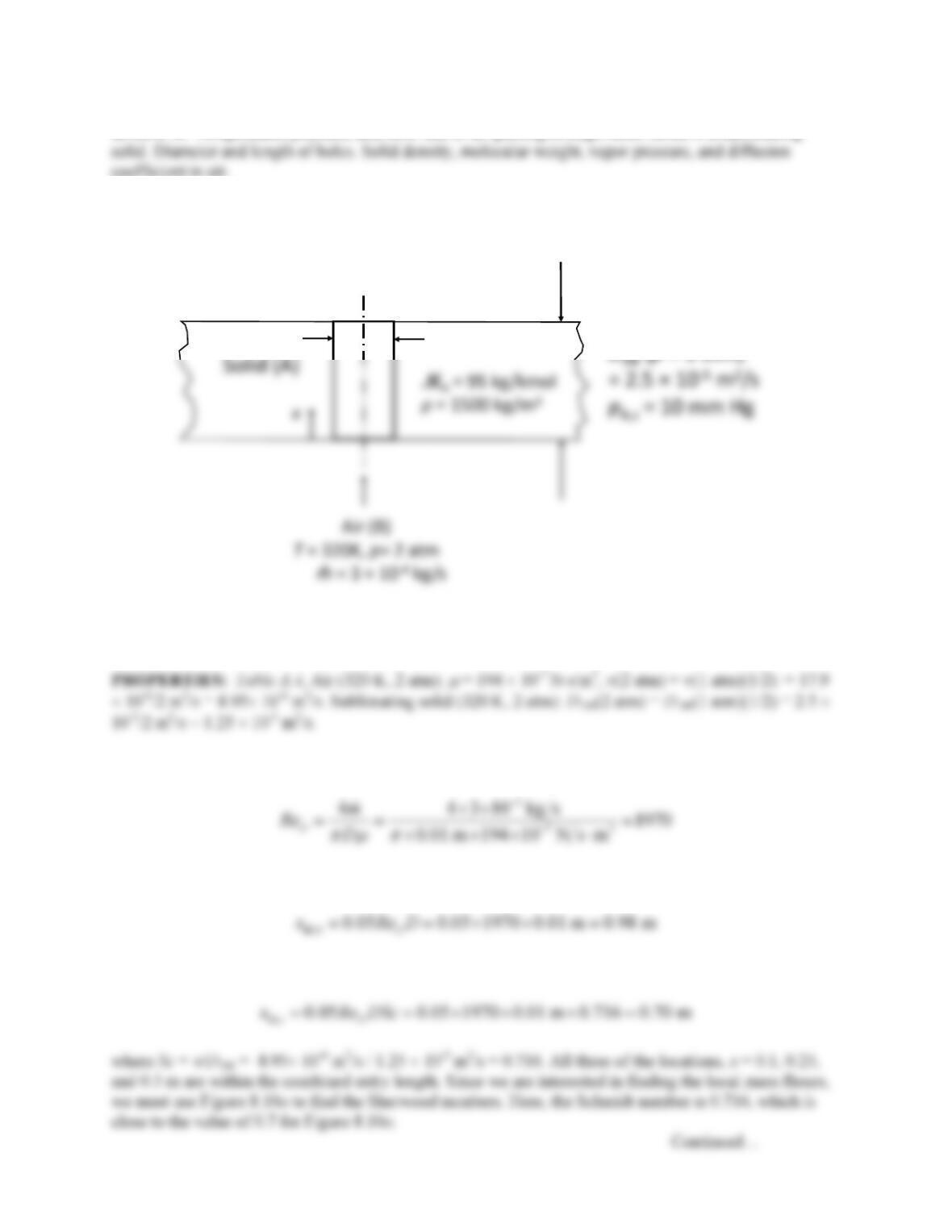
KNOWN: Temperature, pressure, and flow rate of air passing through holes bored in a sublimating
coefficient in air.
FIND: Local mass fluxes from the solid at x = 0.1, 0.25, and 0.5 m. Estimated hole diameters after 30
minutes operation.
SCHEMATIC:
L= 0.5m
D= 10 mm
ASSUMPTIONS: (1) Steady–state conditions, (2) Constant properties, (3) Heat-mass analogy
applicable, (4) Negligible concentration of sublimated vapor in the air (
r
A,m = 0), (5) Sublimated vapor
can be approximated as an ideal gas.
ANALYSIS: The Reynolds number is:
The flow is laminar. From Equation 8.3, the hydrodynamic entry length is:
By analogy with Equation 8.23, the concentration entry length is:
PROBLEM 8.95 (Cont.)
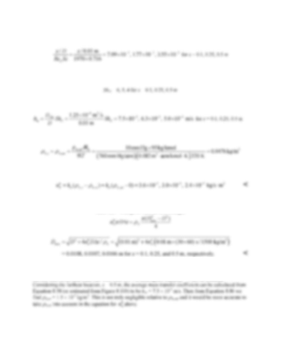
The inverse Graetz numbers for the three locations are:
The Sherwood numbers are roughly estimated from Figure 8.10a for the case of combined entry length
and constant surface temperature (analogous to constant surface concentration):
Then,
The saturation density of the solid can be found from its vapor pressure:
Then the mass fluxes at the three locations are:
The change in diameter can be estimated from the mass flux:
mass loss = change in mass as hole enlarges
COMMENTS: (1) The change in hole diameter is small relative to the diameter. If the change were
larger (for example, over a longer time period), it would be necessary to account for the change in mass
transfer coefficient and mass flux with time. (2) The assumption that
r
PROBLEM 8.96
KNOWN: Air flow over roughened section of tube constructed from naphthalene.
FIND: Mass and heat transfer convection coefficients associated with the roughened section;
contrast these results with those for a smooth section.
ASSUMPTIONS: (1) Steady-state conditions, (2) Heat-mass transfer analogy applicable, (3)
Negligible naphthalene vapor in airstream, rA,m = 0, (4) Constant properties, (5) Naphthalene vapor
behaves as perfect gas.
PROPERTIES: Table A-4, Air (300K, 1 atm): ν = 15.89 × 10⁻⁶ m2/s, k = 0.0263 W/m⋅K, Pr =
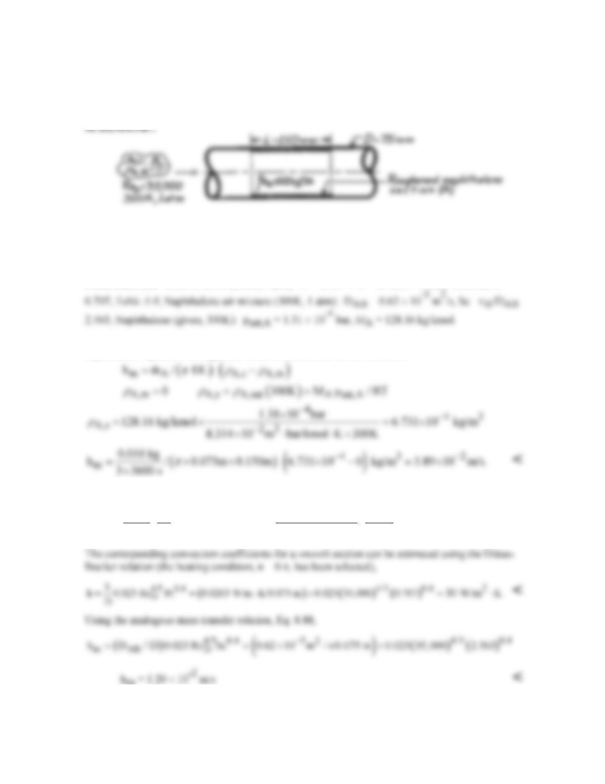
ANALYSIS: Using the rate equation with the experimentally observed sublimination rate of
naphthalene vapor, the average mass transfer coefficient for the section is
Invoking the heat-mass transfer analogy, the associated heat transfer coefficient is
1/3 1/3
22
m52
AB
k Pr 0.0263 W/m K 0.707
h h 3.89 10 m/s 107 W/m K.
D Sc 2.563
0.62 10 m / s
−−
⋅
==×=⋅
×
<
COMMENTS: The effect of roughening is to increase the convection coefficients over the
corresponding value for the smooth condition; in this case, by a factor of approximately 3.5.
PROBLEM 8.97
KNOWN: Density and flow rate of gas through a tube with evaporation or sublimation at the tube
surface.
FIND: (a) Longitudinal distribution of mean vapor density, (b) Total rate of vapor transfer.
SCHEMATIC:
ASSUMPTIONS: (1) Steady, incompressible flow, (2) Flow rate is independent of x, (3) Negligible
chemical reactions, (4) Uniform perimeter P.
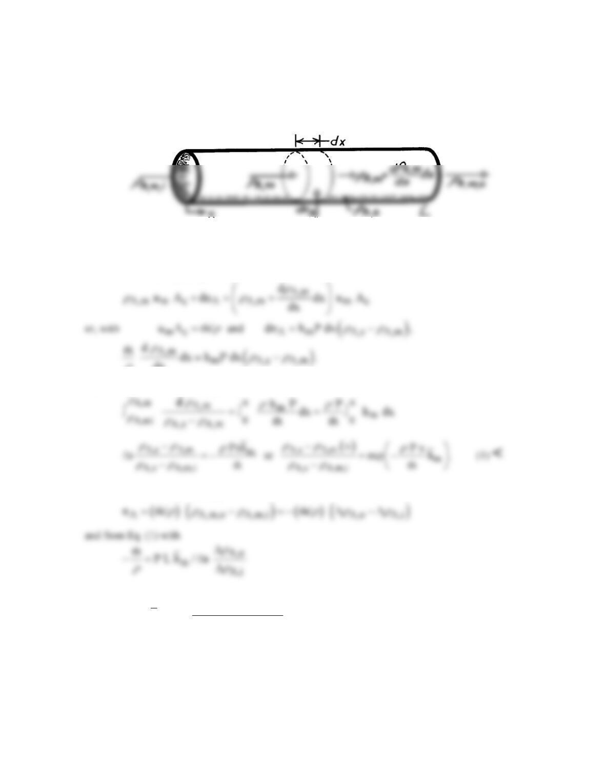
ANALYSIS: (a) Applying conservation of species to a differential control volume
dx
r
Separating variables and integrating,
(b) With
A A,s A,m ,
rr r
∆≡ −
it follows that
( )
A,o A,i
Am
A,o A,i
n h P L .
n/
rr
rr
∆ −∆
=∆∆
<
COMMENTS: Due to the addition of vapor,
m
will actually increase with x. However, if the
specific humidity of the saturated gas–vapor mixture is small (as is usually the case), the change in
m
will be small.
PROBLEM 8.98
KNOWN: Flow rate and temperature of air. Tube diameter and length. Presence of water film on
tube inner surface.
FIND: (a) Vapor density at tube outlet, (b) Evaporation rate.
SCHEMATIC:
ASSUMPTIONS: (1) Steady, incompressible flow, (2) Constant flow rate, (3) Isothermal system
(water film maintained at 25°C).
PROPERTIES: Table A-4, Air (1 atm, 298 K): r = 1.1707 kg/m3, m = 183.6 × 10⁻⁷ N⋅s/m2, ν =
15.71 × 10⁻⁶ m2/s; Table A-6, Water vapor (298 K): rA,sat = 1/vg = (1/44.25 m3/kg) = 0.0226
kg/m3; Table A-8, Air-vapor (298 K): DAB = 26 × 10–6 m2/s; Sc = ν/DAB = 0.60.
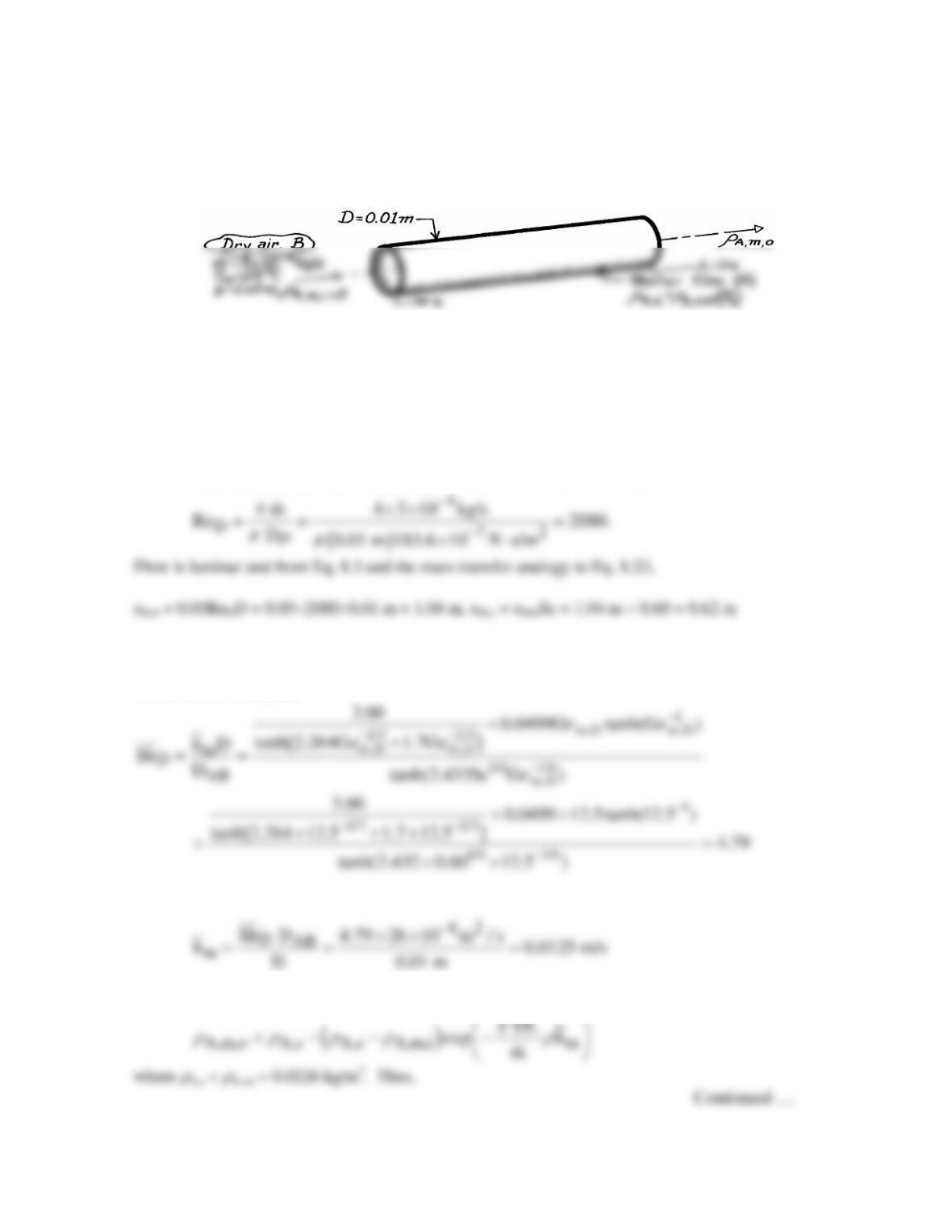
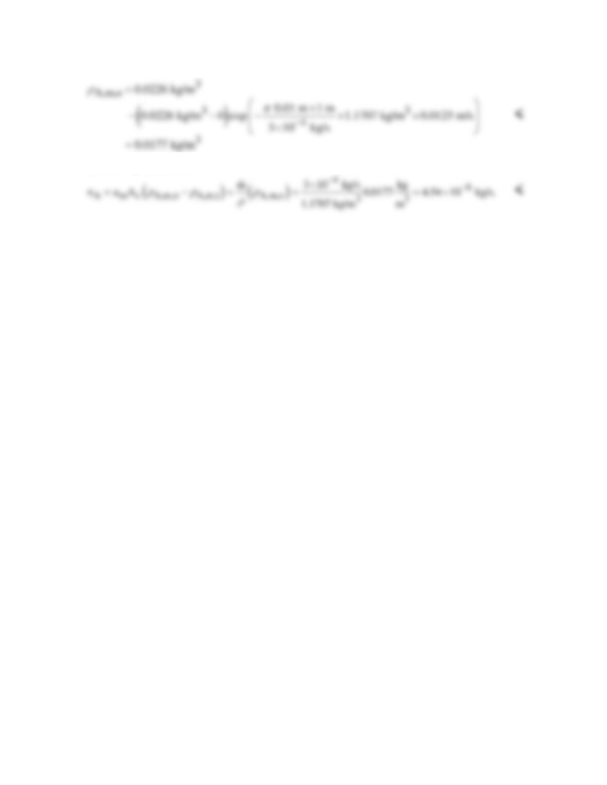
ANALYSIS: (a) We begin by determining the whether the flow is laminar or turbulent.
Thus this is a combined entry length situation and the mass transfer analogy to the Baehr and Stephan
correlation, Eq. 8.58, is appropriate. By analogy to Eq. 8.56, Gzm,D = (D/L)ReDSc = (0.01 m/1 m)
×2080×0.60 = 12.5, and
From Equation 8.86,
PROBLEM 8.98 (Cont.)
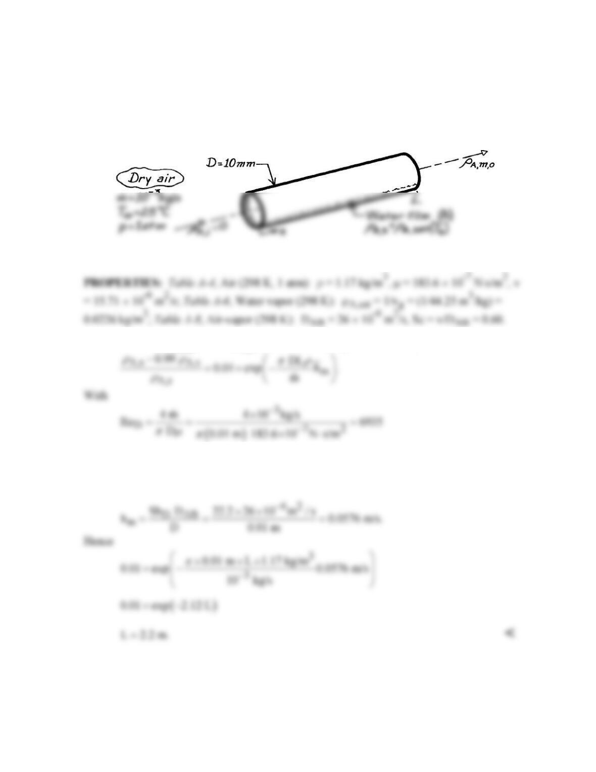
(b) The evaporation rate is
PROBLEM 8.99
KNOWN: Flow rate and temperature of air in circular tube of prescribed diameter. Inner
tube surface is wetted and at same temperature as air. Flow is fully developed and inlet air is
dry.
FIND: Tube length required to reach 99% of saturation.
SCHEMATIC:
ASSUMPTIONS: (1) Steady, incompressible flow, (2) Constant flow rate.
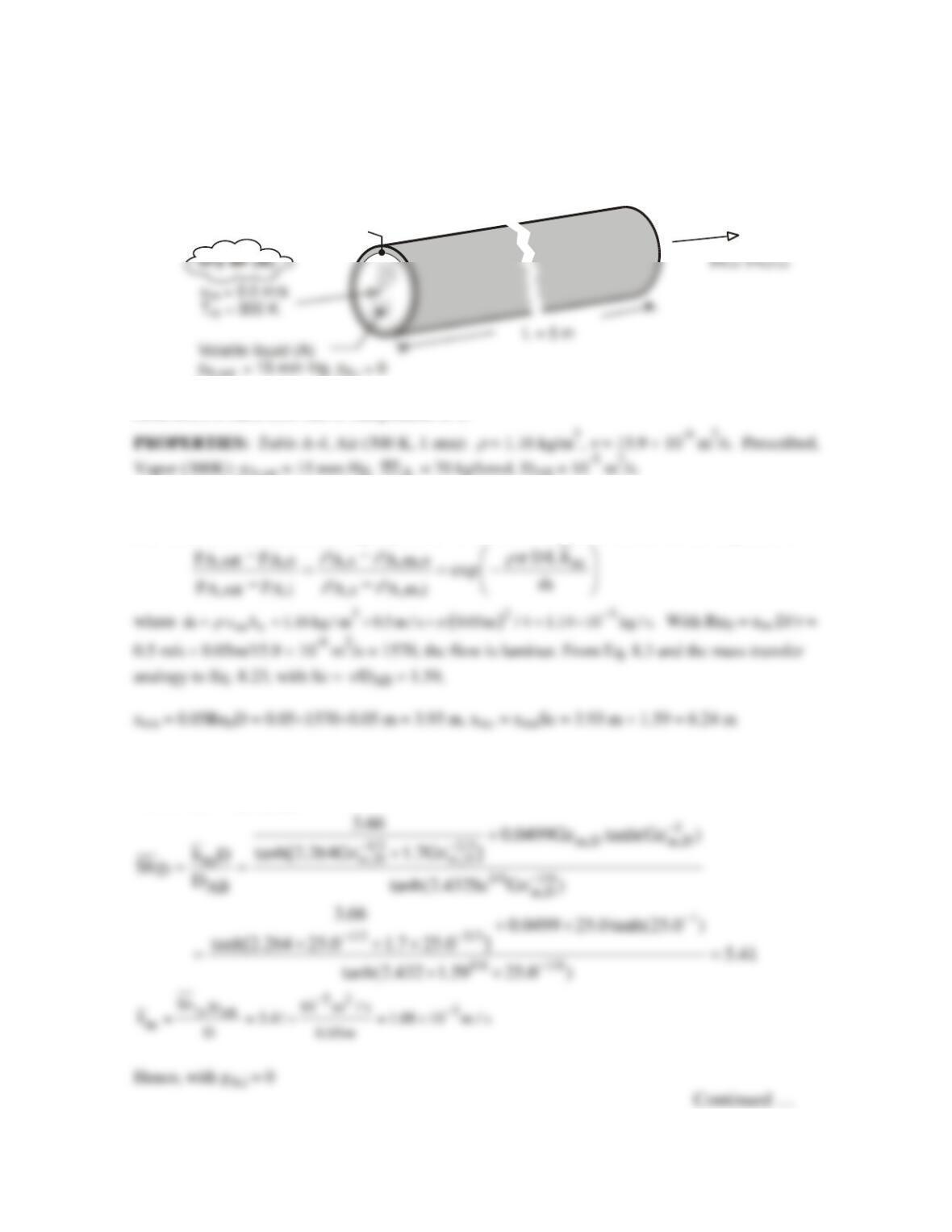
ANALYSIS: If rA,m,o = 0.99 rA,s, it follows from Equation 8.86 that
the flow is turbulent and from Eq. 8.88
( ) ( )
4/5 0.4
4/5 0.4
DD
Sh 0.023 Re Sc 0.023 6935 0.60 22.2= = =
COMMENT: With ReD < 10,000, the mass transfer analog of the Gnielinski correlation would be
preferable.
PROBLEM 8.100
KNOWN: Tube length, diameter and temperature. Air temperature and velocity. Saturation
pressure of thin liquid film and properties of vapor.
FIND: (a) Partial pressure and mass fraction of vapor at tube exit, (b) Mass rate at which liquid is
removed from the tube.
SCHEMATIC:
A,sat A,i
D = 0.05 m
ASSUMPTIONS: (1) System is isothermal at 300K, (2) Steady, incompressible flow, (3) Perfect gas
behavior, (4) Mass flow rate is independent of x.
A
ANALYSIS: (a) With the vapor assumed to behave as an ideal gas, pA = CA
ℜ
T =
r
A
( )
/AT,ℜM
and isothermal conditions, the vapor pressure at the outlet may be obtained from the expression
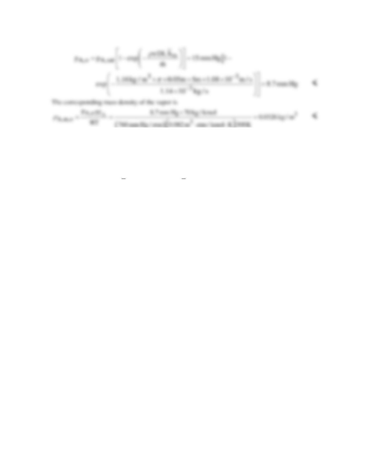
Thus this is a combined entry length situation and the mass transfer analogy to the Baehr and Stephan
correlation, Eq. 8.58, is appropriate. By analogy to Eq. 8.56, Gzm,D = (D/L)ReDSc = (0.05 m/5 m)
×1570×1.59 = 25.0, and
PROBLEM 8.100 (Cont.)
()
(b) The evaporation rate is
( )
32 3 5
A m c A,m,o A,m,i
n u A 0.5m / s 1.96 10 m 0.0326 kg / m 3.20 10 kg / s
rr
−−
= − = ×× × = ×
<
COMMENTS: (1) Since the evaporation rate (nA = 3.2 × 10⁻⁵ kg/s) is much less than the air flow
rate (
m
= 1.14 × 10⁻³ kg/s), the assumption of a fixed flow rate is reasonable. (2) The evaporation
rate is also given by nA =
m
h
π D L ∆
r
A,lm = –
m
h π D L
r
A,m,o/ln [(pA,sat – pA,o)/pA,sat] = 3.22 ×
10-5 kg/s, which agrees with the calculation of part (b).
PROBLEM 8.101
KNOWN: Air flow rate through trachea of diameter D and length L.
FIND: (a) Average mass transfer convection coefficient,
m
h,
and (b) Rate of water loss per day
(liter/day).
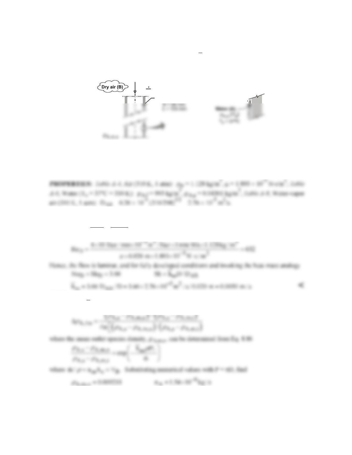
SCHEMATIC:
Trachea
T
m
= 310 K
r
A,m,i
= 0
V = 10 liter/min
B
ASSUMPTIONS: (1) Trachea can be approximated as a smooth tube with uniform surface
temperature, (2) Laminar, fully developed flow, (3) Trachea inner surface is saturated with water at
body temperature, Ts = 37°C, (4) Negligible water vapor in air at 310 K during inhalation, and (5)
Heat–mass analogy is applicable.
ANALYSIS: (a) Begin by characterizing the air (B) flow in the trachea modeled as a smooth tube,
B
D
4m 4
Re DD
r
πm πm
∀
= =
(b) The species (A) transfer rate equation, Eq. 8.83, has the form
A m s A, m
n hA
r
= ∆
A,m,o A
The volumetric rate of water loss on a daily basis, assuming a 12 hour inhalation period, is
()
( )
6 33 3
A
V 1.54 10 kg / s / 993 kg / m 10 liter / m 3600 s / h 24 h / day
−
=× × ××
A
V 0.134 liter / day=
<
PROBLEM 8.102
KNOWN: Air (species B) is in fully developed, laminar flow as it enters a circular tube wetted with
liquid A (water). Tube length and diameter. Flow rate of air and system temperature.
FIND: (a) Governing differential equation for species transfer, (b) Heat transfer analog and an
expression for
Sh
D
, (c) General expression for rA,m,o, (d) Value of rA,m,o for prescribed conditions.
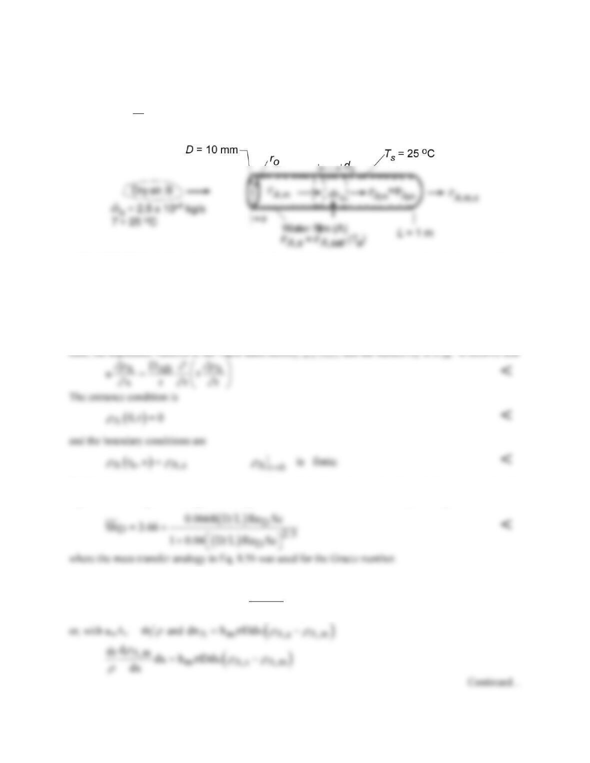
SCHEMATIC:
ASSUMPTIONS: (1) Steady, incompressible flow, (2) Flow rate is independent of x, (3) Laminar, fully
developed flow (hydrodynamically), (4) Isothermal conditions, (5) Dry air at inlet.
PROPERTIES: Table A.4, Air (298 K, 1 atm): r = 1.1707 kg/m3, m = 183.6 × 10⁻⁷ N⋅s/m2, ν = 15.71 ×
10-6 m2/s; Table A.6, Water vapor (298 K): rA,sat = 1/vg = 0.0266 kg/m3; Table A.8, Air-vapor (298 K):
DAB = 26 × 10-6 m2/s, Sc = ν/DAB = 0.60.
ANALYSIS: (a) The governing differential equation may be inferred by analogy to Eq. 8.48. In this
(b) The foregoing conditions are analogous to those of the thermal entry length condition associated with
Eq. 8.57. Invoking this analogy the average Sherwood number for laminar, fully developed flow is
(c) Applying conservation of species to the differential control volume,
A,m
A,m m c A A,m m c
d
u A dn dx u A
dx
r
rr
+= +
PROBLEM 8.102 (Cont.)
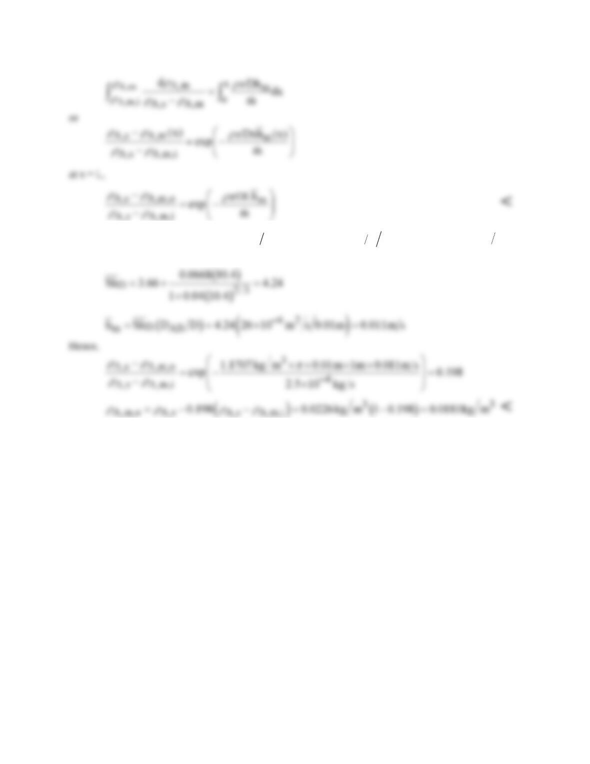
(d) For the prescribed conditions, ReD =
4m D
πm
=
4 2 5 10 0 01 183 6 10
4 7 2
. . .× × ⋅
− −
kg s m N s m
c h af
π
=
1734 and (D/L)ReDSc = (0.01 m/1 m)1734(0.6) = 10.4. Hence,
COMMENTS: Due to evaporation,
m
actually increases with increasing x. However, the increase is
small, and the assumption of fixed
m
is good.