PROBLEM 8.72
KNOWN: Inner and outer tube surface conditions for an annulus.
FIND: (a) Velocity profile, (b) Temperature profile and expression for inner surface Nusselt number.
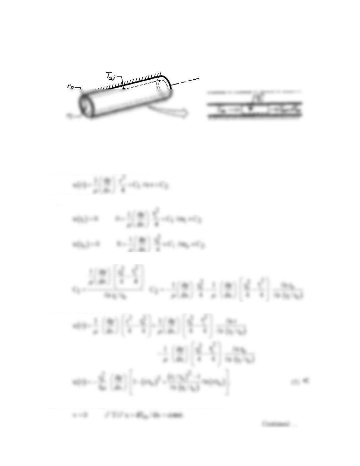
SCHEMATIC:
ASSUMPTIONS: (1) Steady-state conditions, (2) Laminar, fully developed flow, (3) Uniform heat
flux at inner surface, (4) Adiabatic outer surface, (5) Constant properties, (6) Applicability of Eq.
8.34.
ANALYSIS: (a) From Section 8.1.3, the general solution to Eq. 8.12, which also applies to annular
flow as represented in Figure 8.11, is
Applying the boundary conditions,
Hence,
and the velocity distribution is
(b) For fully developed conditions with uniform surface heat flux,
PROBLEM 8.72 (Cont.)
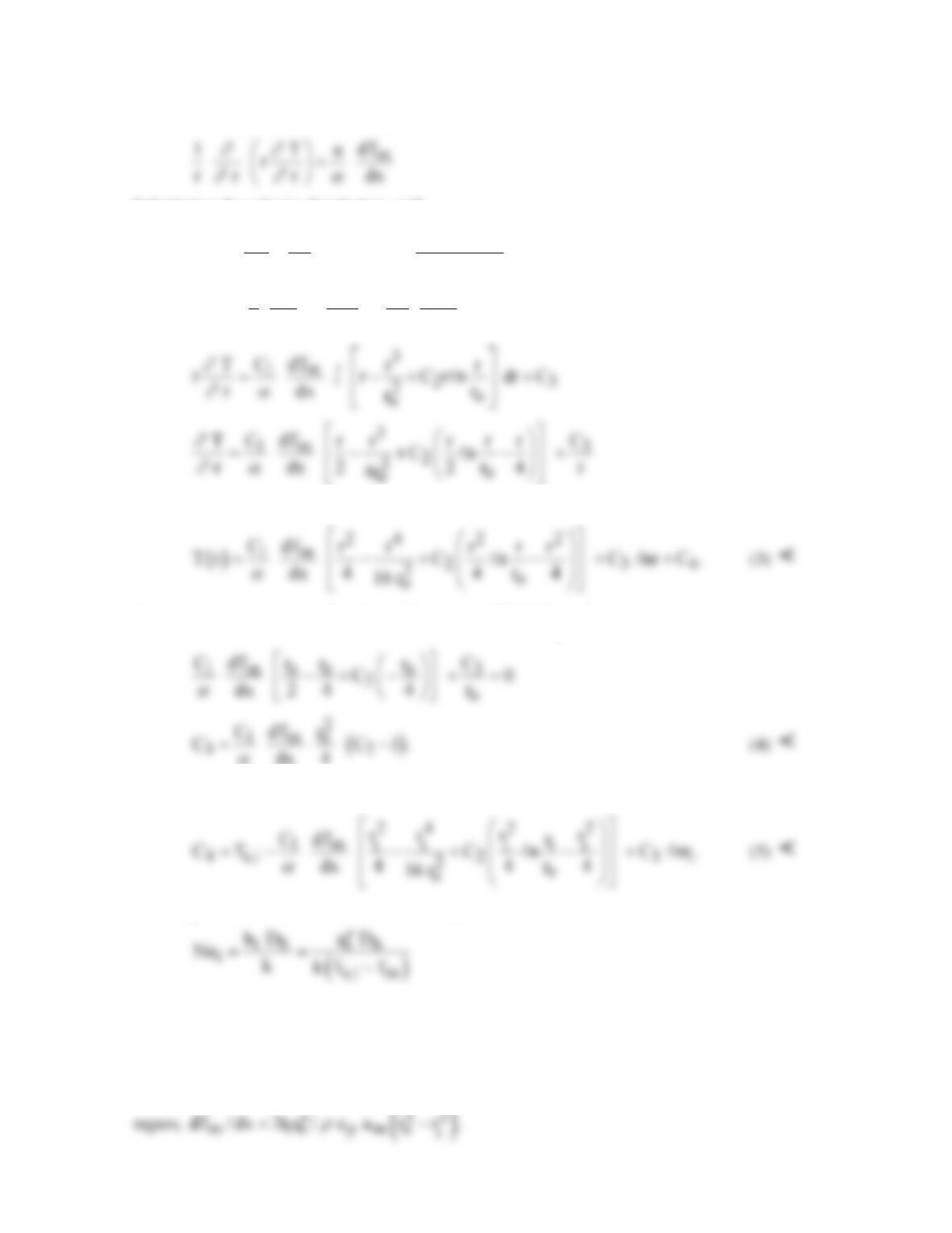
Hence, from Eq. 8.48, which also applies for annular flow,
Substituting the velocity distribution, with
( )
( )
2
2io
o
12
io
r /r 1
rdp
C C
4 dx n r / r
m
−
=−=
(2)
it follows that
( ) ( )
2
1m o2o
1 T C dT
r 1 r/r C n r/r .
r r r dx
∂∂
∂∂α
= −+
and the temperature distribution is
From the requirement that
o
q 0,
′′ =
it follows that
)
o
r
T/ r 0.
∂∂
=
Hence,
dx 4
α
From the condition that T(ri) = Ts,i, it follows that
From Eqs. 8.67 and 8.69, the inner surface Nusselt number is
where Dh = 2(ro – ri). To obtain a workable form of Nui, the mean temperature Tm must be
evaluated. This may be done by substituting Eqs. (1) and (3) into Eq. 8.26 and evaluating um by
substituting Eq. (1) into Eq. 8.8. Since the integrations are long and tedious, they are not provided.
COMMENTS: From an energy balance performed for a differential control volume in the annular
PROBLEM 8.73
KNOWN: Dimensions and surface thermal conditions for a concentric tube annulus. Water flow
rate and inlet temperature.
FIND: (a) Tube length required to achieve desired outlet temperature, (b) Inner tube surface
temperature at outlet.
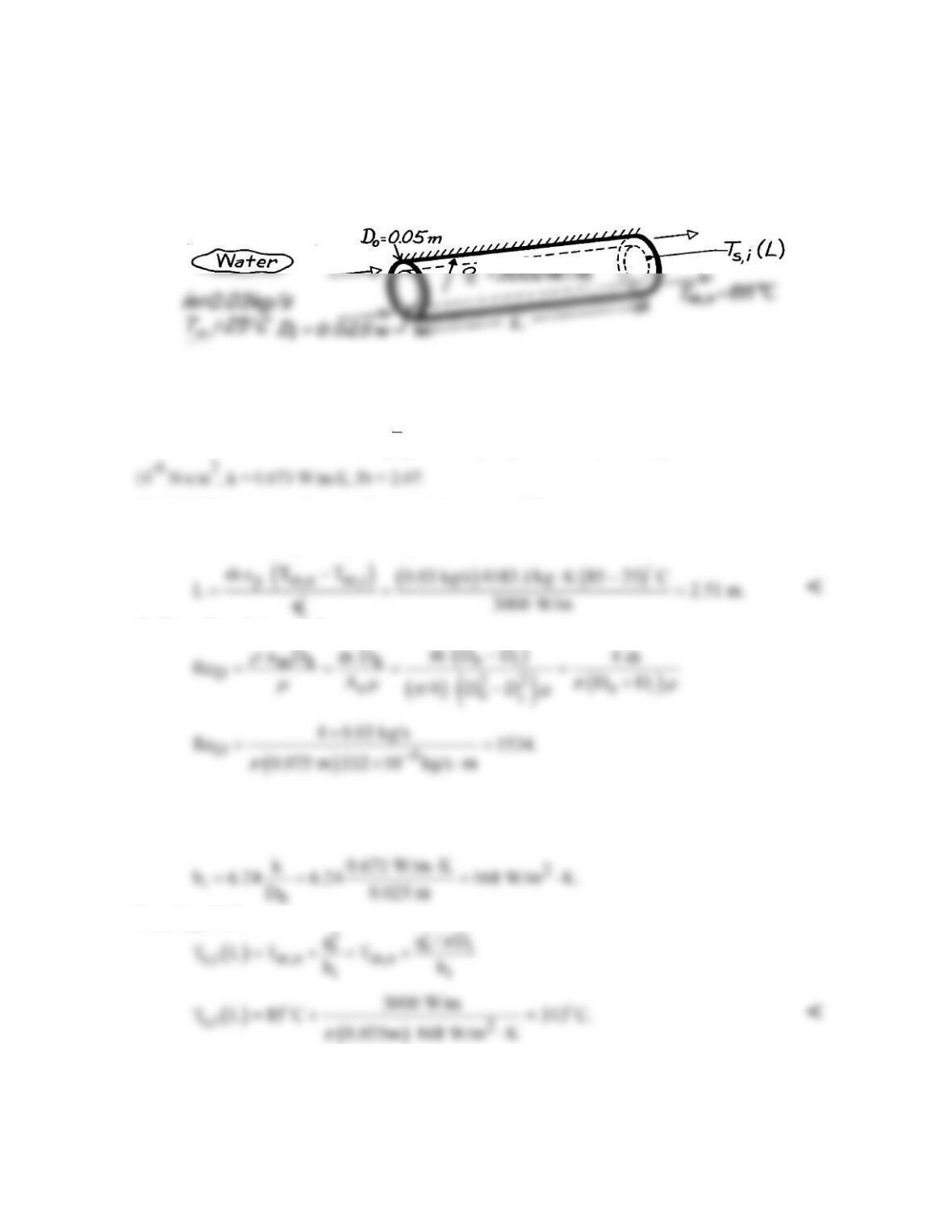
SCHEMATIC:
ASSUMPTIONS: (1) Steady-state conditions, (2) Uniform heat flux at inner surface, (3) Adiabatic
outer surface, (4) Fully developed flow at exit, (5) Constant properties, (6) Incompressible liquid with
negligible viscous dissipation.
PROPERTIES: Table A-6, Water
( )
m
T 328K :=
cp = 4183 J/kg⋅K; (Tm,o = 358K): m = 332 ×
ANALYSIS: (a) From the overall energy balance, Eq. 8.34,
( )
i p m,o m,i
q q L m c T T
′
= = −
(b) From Eqs. 8.1 and 8.5,
Hence the flow is laminar, and with Di/Do = 0.5, it follows from Eq. 8.72 and Table 8.3
i ii
Nu Nu 6.24= =
From Eq. 8.67,
COMMENTS: Unless the water is pressurized, local boiling would occur at the tube surface,
causing hi to be larger.
PROBLEM 8.74
KNOWN: A concentric tube arrangement for removing heat generated from a biochemical reaction
in a settling tank. Water is supplied to the annular region at rate of 0.2 kg/s.
FIND: (a) The inlet temperature of the supply water that will provide for an average tank surface
temperature of 37°C; assume and then justify fully developed flow and thermal conditions; and (b)
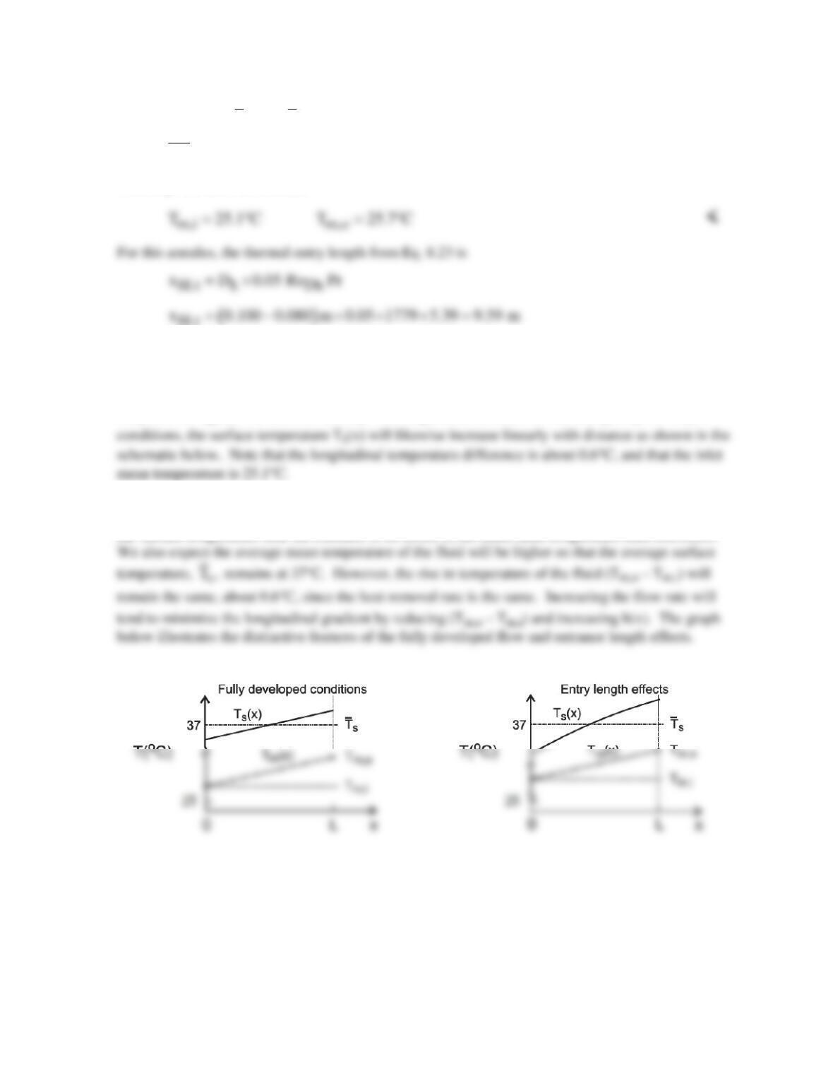
Sketch the water and surface temperatures along the flow direction for two cases: the fully developed
conditions of part (a), and when entrance effects are important. Comment on the features of the
temperature distributions, with particular attention to the longitudinal gradient on the tank surface.
What change to the system or operating conditions would you make to reduce the gradient?
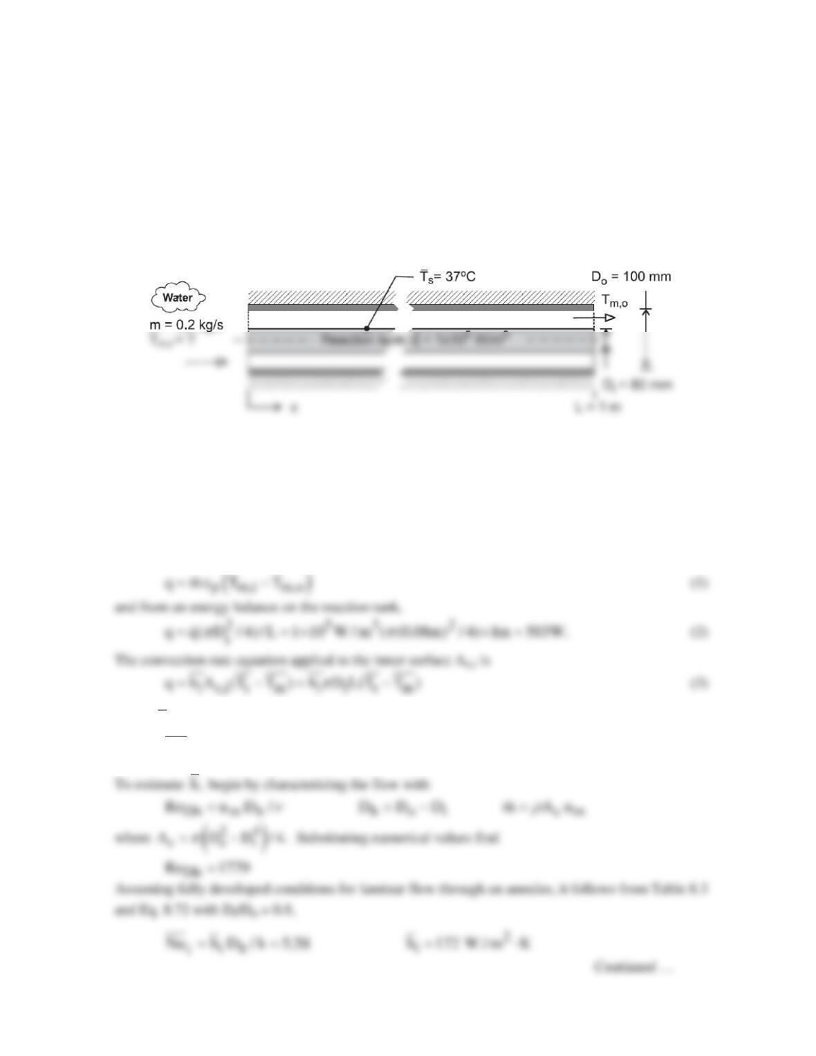
SCHEMATIC:
ASSUMPTIONS: (1) Fully developed flow and thermal conditions, (2) Inner annulus surface has
uniform heat flux, while outer surface is insulated, (3) Constant properties, (4) Incompressible liquid
with negligible viscous dissipation.
PROPERTIES: Table A-6, Water (Tm = 304 K): r = 995.6 kg/m3, cp = 4178 J/kg⋅K, ν = 7.987 ×
10-7 m2/s, k = 0.618 W/m⋅K, Pr = 5.39.
ANALYSIS: (a) The overall energy balance on the fluid passing through the concentric tube is
where
s
T
is the average inner surface temperature and
( )
m m,i m,o
T T T / 2.= +
(4)
PROBLEM 8.74 (Cont.)
Using Eq. (3) with
i
h,
and
s
T 37 C,= °
and q from Eq. (2), find
m
T 25.4 C= °
From Eqs. (1) and (4), calculate
Since L = 1 m, we conclude that entry length effects are significant, and the fully developed flow
assumption is approximate.
(b) Since the fluid is being heated by flow over a surface with uniform heat flux, the mean fluid
temperature, Tm(x), will increase linearly with longitudinal distance x. Assuming fully developed
Considering now entrance length effects, the convection coefficient is no longer uniform, and will be
largest near the entrance, and larger than for the fully developed flow everywhere. Hence, we expect
the surface temperature near the entrance to be closer to the mean fluid temperature than elsewhere.
s
COMMENTS: The thermophysical properties required in the convection correlation and the energy
equations should be evaluated at Tm = (Tm,i + Tm,o)/2 ≈ 298 K.
PROBLEM 8.75
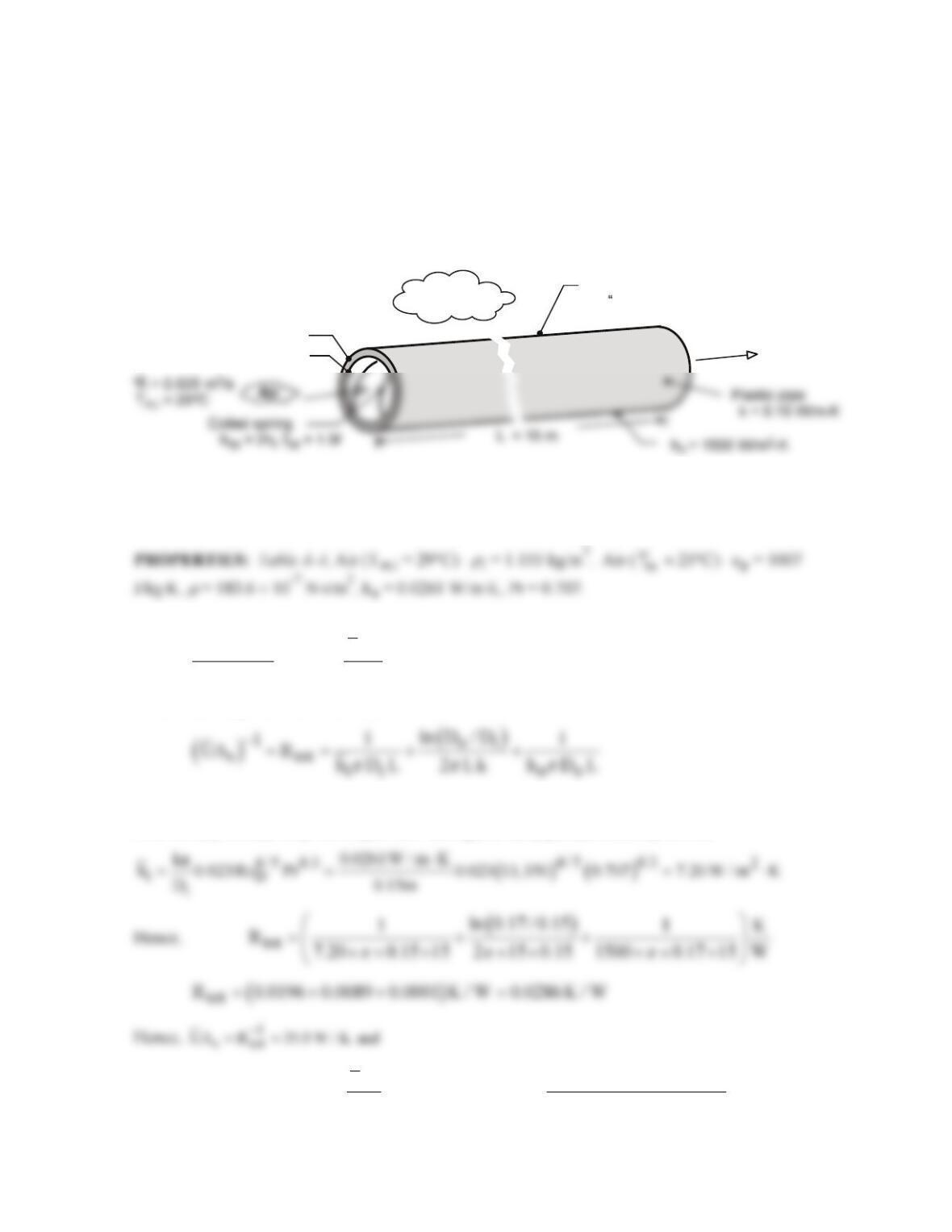
KNOWN: Dimensions and thermal conductivity of plastic pipe. Volumetric flow rate and
temperature of inlet air. Enhancement of inner convection coefficient and friction factor associated
with coiled spring. Thermal resistance of coating on outer surface.
FIND: (a) Air outlet temperature and fan power requirement without coating and coiled spring, (b)
Effect of coiled spring on air outlet temperature and fan power, (c) Effect of coating on outlet
temperature.
SCHEMATIC:
R = 0.050 -K/W
t,c
m
2
Thin film
Water
T = 17 C
o
oo
T
m,o
D
o
= 0.17 m
D
i
= 0.15 m
ASSUMPTIONS: (1) Steady-state, (2) Negligible heat transfer from air in vertical pipe sections, (3)
Air is ideal gas with negligible viscous dissipation and pressure variation, (4) Smooth interior surface
without spring, (5) Negligible coating thickness, (6) Constant properties.
ANALYSIS: (a) From Eq. (8.45a),
m,o s
m,i p
TT UA
exp
T T mc
∞
∞
−= −
−
where, from Eqs. (3.36) and (3.37),
With
ii
m 0.0289 kg / s
r
= ∀=
and
Di
Re 4m / D 13, 350,
πm
= =
the pipe flow is turbulent. With L/Di =
100, we may assume fully developed flow throughout the pipe, and from Eq. (8.60),
( )
( )
s
m,o m,i
p
UA 35.0 W / K
T T T T exp 17 C 12 C exp 20.6 C
m c 0.0289 kg / s 1007 J / kg K
∞∞
= + − − = °+ ° − = °
×⋅
<
Continued …
PROBLEM 8.75 (Cont.)
From Eq. (8.21), f = [0.790ln(ReD) – 1.64]– 2 = 0.0291. Hence, from Eqs. (8.22a) and (8.22b), with
m,i
u
ic
/ A 1.415 m / s,=∀=
(b) With hcp = 2hi = 14.4 W/m2⋅K, the inner convection resistance is reduced from 0.0196 K/W to
0.0098 K/W and hence the total resistance from 0.0286 K/W to 0.0188 K/W. It follows that
s
UA 53.2 W / K=
and
(c) With the coating of organic matter, there is an additional thermal resistance of the form Rt,c =
COMMENTS: (1) The fan power requirement is small, and the process is economical, with or
without the coiled spring. (2) Heat transfer enhancement associated with the coiled spring is
manifested by a 34% reduction in the total thermal resistance and a 1.7°C reduction in the outlet
temperature. (3) Fouling of the outer surface increases the total resistance by 22% and the outlet
temperature by 0.9°C. The penalty is not severe but could be ameliorated by periodic cleaning of the
surface.
PROBLEM 8.76
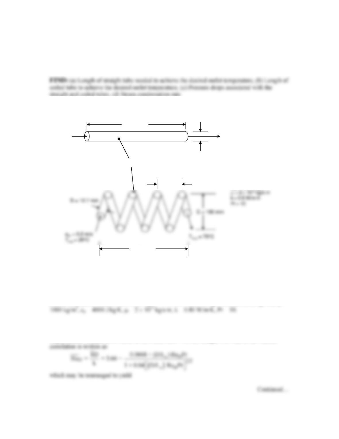
KNOWN: Inlet and desired outlet temperature of a pharmaceutical fluid flowing in a straight
tube or coiled tube of known diameter. Inlet velocity and tube surface temperature.
straight and coiled tubes, (d) Steam condensation rate.
SCHEMATIC:
L
cl
S = 25 mm
(b)
(a)
u
m
= 0.2 m/s
T
m,i
= 25°C
L
s
D = 12.7 mm
T
s
= 100°C
T
m,o
= 75°C
r= 1000 kg/m
3
c
p
= 4000 J/kg·K
Fluid properties
L
cl
S = 25 mm
(b)
(a)
u
m
= 0.2 m/s
T
m,i
= 25°C
L
s
D = 12.7 mm
T
s
= 100°C
T
m,o
= 75°C
r= 1000 kg/m
3
c
p
= 4000 J/kg·K
Fluid properties
Fluid properties
r= 1000 kg/m
3
c
p
= 4000 J/kg·K
.
ASSUMPTIONS: (1) Constant properties, (2) Incompressible liquid and negligible viscous
dissipation, (3) Steady-state conditions, (4) fully developed hydrodynamic conditions at the
entrance.
PROPERTIES: Steam (Table A.6): hfg (T = 100°C) = 2257 kJ/kg. Pharmaceutical (given): r =
ANALYSIS:
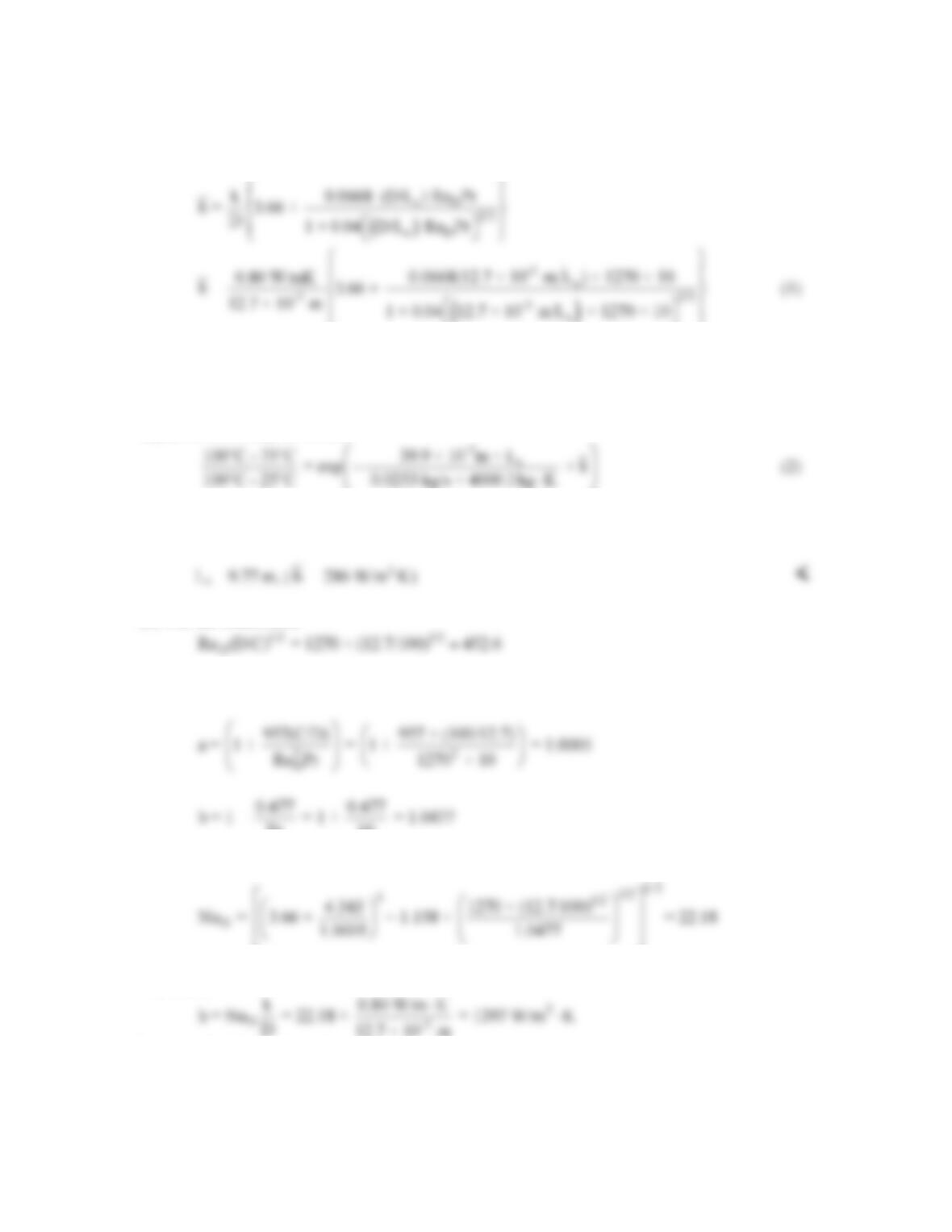
(a) From Problem 8.21, ReD = rumD/m=1270 and the flow is laminar for both cases. Hence,
augmentation is expected to occur in the coiled tube. For the straight tube case a, the Hausen
PROBLEM 8.76 (Cont.)
From Problem 8.21 m
= 0.0253 kg/s and the tube perimeter is
-3 -3
P = πD = π × 12.7 × 10 m = 39.9 × 10 m
Equation 8.41b may be written
Equations (1) and (2) may be solved simultaneously to yield
(b) For the coiled tube,
Therefore, C/D = 100/12.7 = 7.87 > 3, Equation 8.77 yields
Pr 10
Therefore Equation 8.76 becomes
Therefore,
Equation 8.41b may be written
Continued…
PROBLEM 8.76 (Cont.)
-3 2
c
100°C – 75°C 3.99 × 10 m × L
= exp × 1397 W/m K
100°C – 25°C 0.0253 kg/s × 4000 J/kg K
−⋅
⋅
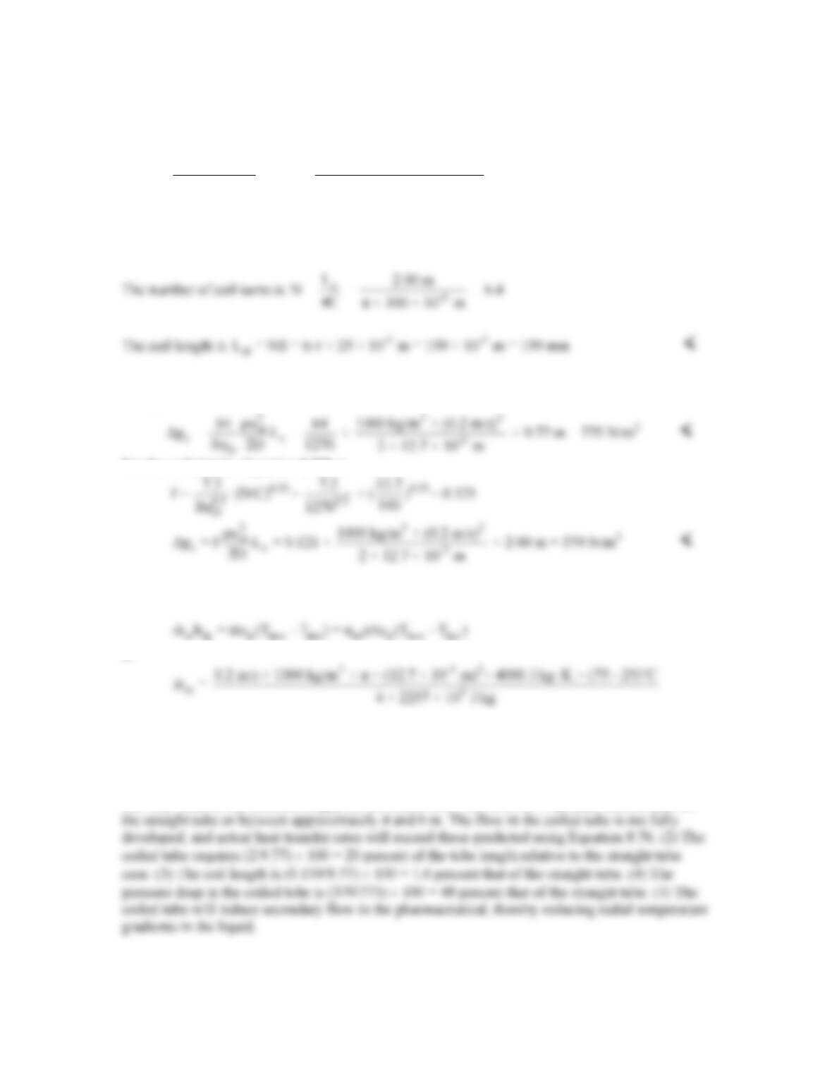
or Lc = 2.00 m
(c) The flow is hydrodynamically fully-developed in the straight tube. From Equations 8.19 and
8.22a,
For the coiled tube, Equation 8.75b is
(d) The steam condensation rate, st
m
, is
or
-3
st
m = 2.25 × 10 kg/s
<
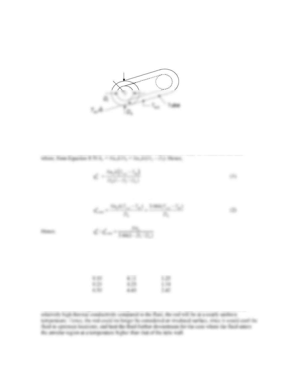
COMMENTS: (1) For the straight tube, xfd,t = 0.05ReDPrD = 0.05 × 1270 × 10 × 12.7×10-3 m =
8m. The value of the entrance length for the coiled tube will be 20 to 50 percent shorter than for
PROBLEM 8.77
KNOWN: Laminar flow within a tube of diameter Do. Inner rod diameter, Di. Mean fluid
temperature, Tm, and tube wall temperature, Ts,o.
FIND: Ratio of heat transfer from the fluid to the tube wall for Di/Do = 0, 0.10, 0.25 and 0.50.
SCHEMATIC:
ASSUMPTIONS: (1) Fully developed, laminar flow, (2) Constant properties, (3) Negligible
conduction in the rod.
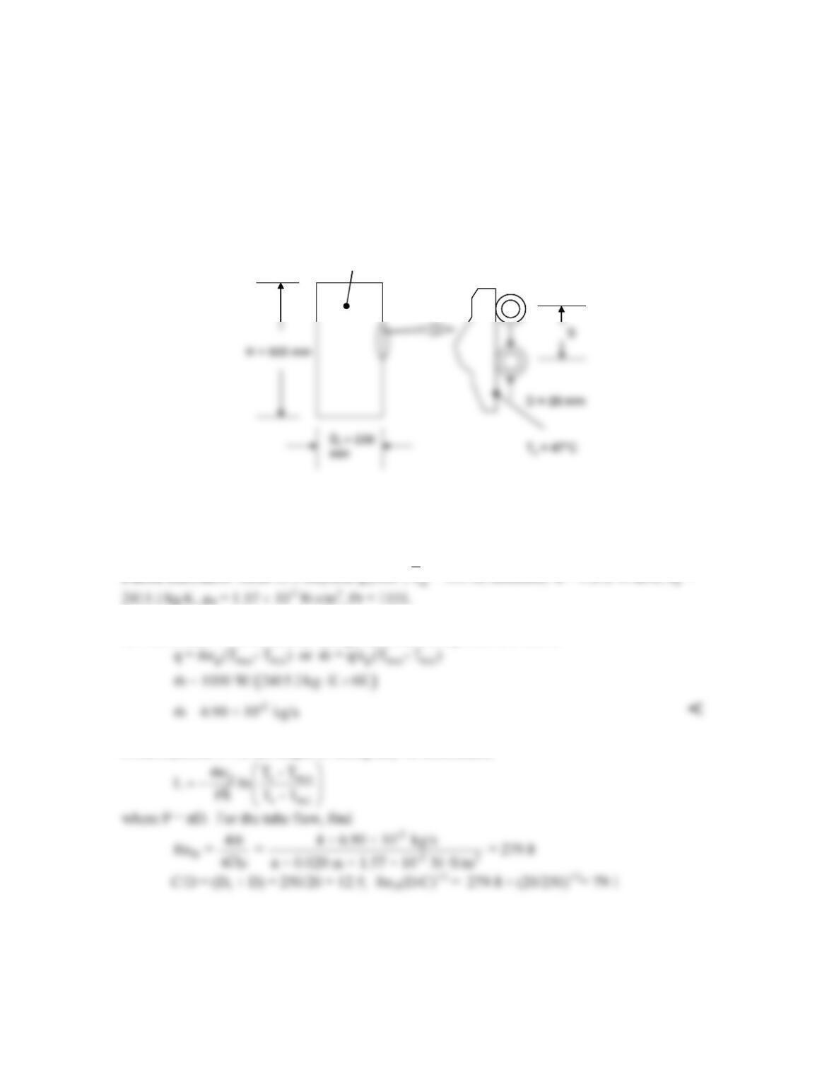
ANALYSIS: A control volume analysis about the inner rod reveals that there is no heat transfer to
or from the rod. Hence, it acts as an insulated surface. Equation 8.68 may be written for the tube
Without the rod, Di/Do = 0 and Nuo = 3.66, yielding
From Table 8.2,
Di/Do Nuo
,wo
/
oo
qq
′′ ′′
<
0 3.66 1
COMMENTS: (1) The proposed scheme enhances the heat transfer between the fluid and the tube
wall, (2) The fluid temperature will change as the fluid flows in the axial direction. If the rod is of
Rod
Rod
PROBLEM 8.78
KNOWN: Tubing with ethylene glycol welded to transformer to remove dissipated power.
Maximum allowable coolant temperature rise of 6°C.
FIND: Required coolant flow rate, tube length and lateral spacing of turns.
SCHEMATIC:
Transformer, 1000 W
Ethylene glycol, Tm,i = 24°C
Transformer, 1000 W
Ethylene glycol, Tm,i = 24°C
ASSUMPTIONS: (1) Constant properties, (2) Incompressible liquid and negligible viscous
dissipation, (3) Steady-state conditions, (4) Negligible tube wall thermal resistance, (5) Fully-
developed flow, (6) All heat dissipated by transformer is transferred to ethylene glycol.
PROPERTIES: Table A.5, ethylene glycol: (
T = 300 K, assumed): k = 0.252 W/m⋅K, cp =
ANALYSIS: From an overall energy balance, the required flow rate is
From Equation 8.41a the length of tubing may be determined,
Equation 8.77 yields
Continued…
PROBLEM 8.78 (Cont.)
Therefore, Equation 8.76 is
Equation 8.41a becomes
COMMENT: (1) Coiling the tube results in a convective heat transfer coefficient that is
10.99/3.66 = 3 times larger than the fully-developed value for a straight tube. (2) For a straight
tube, the thermal entrance length is xfd,t = 0.05ReDPrD = 0.05 × 279.8 × 1151 × 0.02 m = 322 m.
The flow will not be fully–developed, and care must be taken when using the predictions.
PROBLEM 8.79
KNOWN: Geometry and dimensions of a tube with straight and coiled sections. Temperature and
convection coefficient of coolant flowing outside the tube. Inlet temperature, mass flow rate, and
properties of pharmaceutical fluid in tube.
FIND: (a) Outlet temperature of pharmaceutical, (b) Outlet temperature with inner heat transfer
coefficient doubled in straight sections, (c) Effect of left– or right-handed spiral.
SCHEMATIC:
ASSUMPTIONS: (1) Tube wall thermal resistance is negligible. (2) Flow is fully–developed in
coiled section. (3) Flow in last straight section is unaffected by swirl introduced in coiled section. (4)
Constant properties.
PROPERTIES: Pharmaceutical fluid (given): ρ = 1200 kg/m3, μ = 4 × 10⁻³ N∙s/m2, cp = 2000
J/kg∙K, k = 0.5 W/m∙K, Pr = μcp/k = 16.
ANALYSIS:
(a) The Reynolds number is
Thus the flow is laminar.
The flow is thermally developing. With Pr > 5, we can use Equation 8.57 with Equation 8.56,
Pharmaceutical
T
m,i
= 90°C
T
m,o
D = 10 mm
.=
m 0 005 kg/s
Pharmaceutical
T
m,i
= 90°C
T
m,o
D = 10 mm
.=
m 0 005 kg/s
PROBLEM 8.79 (Cont.)
The mean temperature at the end of the first straight section can be found from Equation 8.45a,
Coiled Section. The critical Reynolds number in the coiled section is given by Equation 8.74,
0.5
D,C,h D,C
Re = Re 1 + 12(D/C)
where ReD,C = 2300. Since this must be greater than 2300, the flow in the coiled section, with ReD =
and b = 1 + 0.477/Pr = 1+ 0.477/16 = 1.030. Note that ReD (D/C)1/2 = 58, therefore the criteria for
using Equations 8.76 and 8.77 are satisfied. Thus assuming μs = μ,
and hi = NuDk/D = 498 W/m2∙K.
The outlet temperature of the coiled section can be found from Equation 8.45a, with
As = (π D)(6.5 π C) = 0.048 m2, and the inlet temperature is the outlet temperature of the straight
section:
PROBLEM 8.79 (Cont.)
2nd Straight Section. The overall heat transfer coefficient would be the same as in the 1st straight
section. The outlet temperature can be calculated from Equation 8.45a with the inlet temperature
equal to the outlet temperature of the coiled section.
(b) Repeating the calculations with hi in the straight sections doubled, in the 1st straight section:
-1
22 2
U = 1/730 W/m K + 1/500 W/m K = 297 W/m K
⋅⋅ ⋅
(c) Yes, the orientation of the springs could have an effect, because they introduce swirl that interacts
with the swirl introduced in the coiled section. However, the effect is probably small.
COMMENTS: The analysis is only approximate. In particular, the flow in the last section would be
affected by the swirl introduced in the coiled section, which would in turn affect the heat transfer.
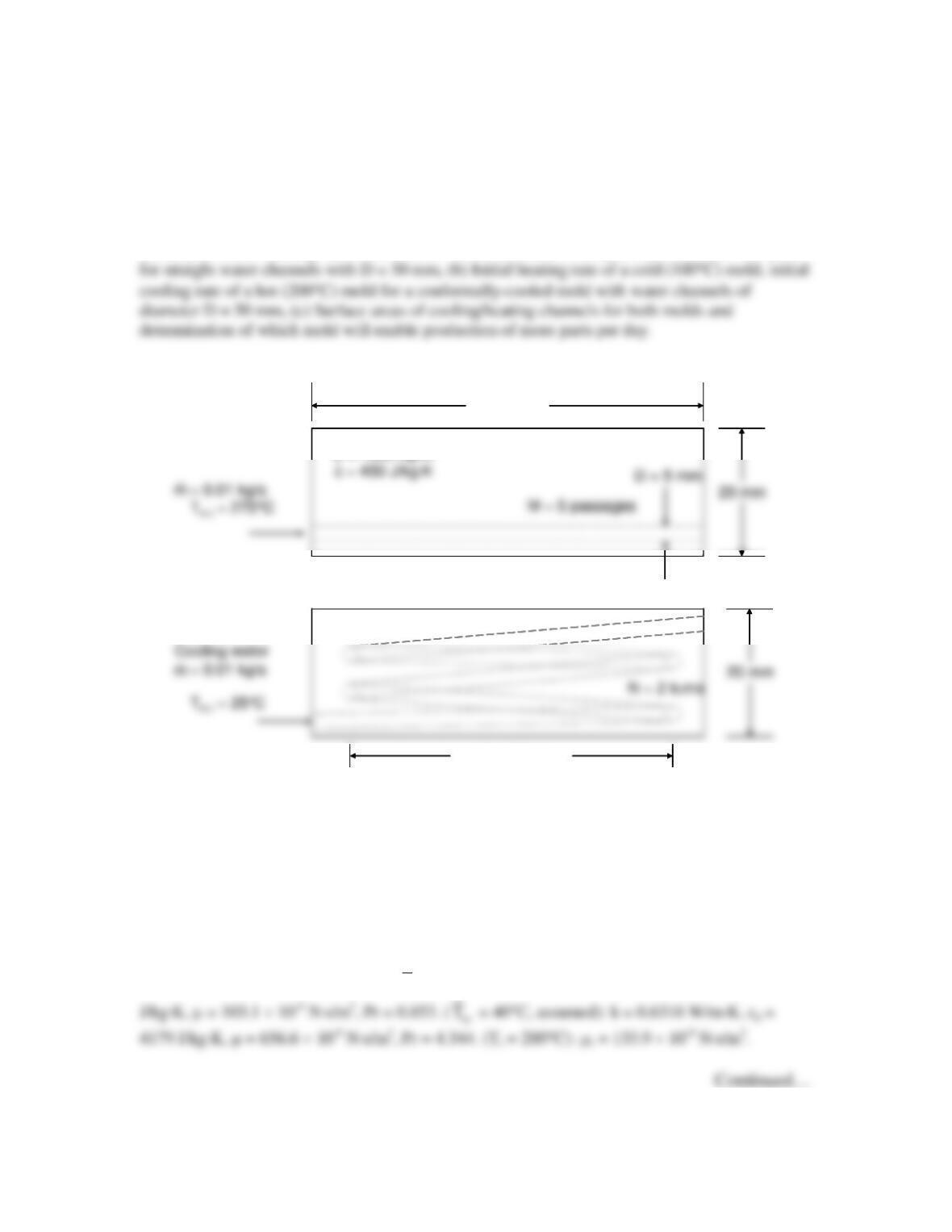
PROBLEM 8.80
KNOWN: Pressurized water inlet temperature and total mass flow rate for mold cooling and
heating. Water channel dimensions for conventional and conformally-cooled mold. Initial hot and
cold mold temperatures, mold dimensions and mold properties.
FIND: (a) Initial heating rate of a cold (100°C) mold, initial cooling rate of a hot (200°C) mold
SCHEMATIC:
Heating water
(a)
(b)
60 mm
Conventional mold (top half is shown)
Conformally–cooled mold (bottom half is shown)
C = 50 mm
r= 7800 kg/m
3
Heating water
(a)
(b)
60 mm
Conventional mold (top half is shown)
Conformally–cooled mold (bottom half is shown)
C = 50 mm
r= 7800 kg/m
3
ASSUMPTIONS: (1) Constant properties, (2) Incompressible liquid and negligible viscous
dissipation, (3) Fully developed hydrodynamic conditions at the entrance, (4) Negligible part
mass, (5) Water sufficiently pressurized to prevent boiling, (6) Negligible heat transfer in short
straight sections of the channel for the conformally-cooled case.
PROPERTIES: Table A.6, water: (
m
T
= 260°C, assumed): k = 0.6038 W/m⋅K, cp = 4989
PROBLEM 8.80 (Cont.)
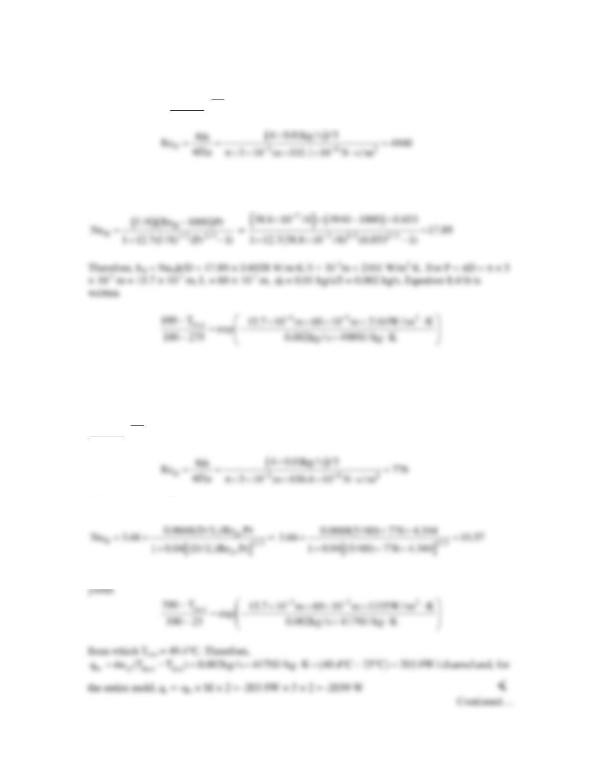
ANALYSIS: (a) Heating,
m
T 260 C.= °
The Reynolds number is
From the Gnielinski correlation, with f = (0.790lnReD – 1.64)-2 = (0.790ln4940 – 1.64)-2 = 38.8 ×
10-3,
from which Tm,o = 243°C. Therefore,
w p m,o m,i
q mc (T T ) 0.002kg / s 4989J / kg K (243 C 275 C) 319W / channel= − = × ⋅ × °− ° =
and, for
the entire mold, qh = –qw × M × 2 = 319W × 5 × 2 = 3190 W <
Cooling,
m
T 40 C.= °
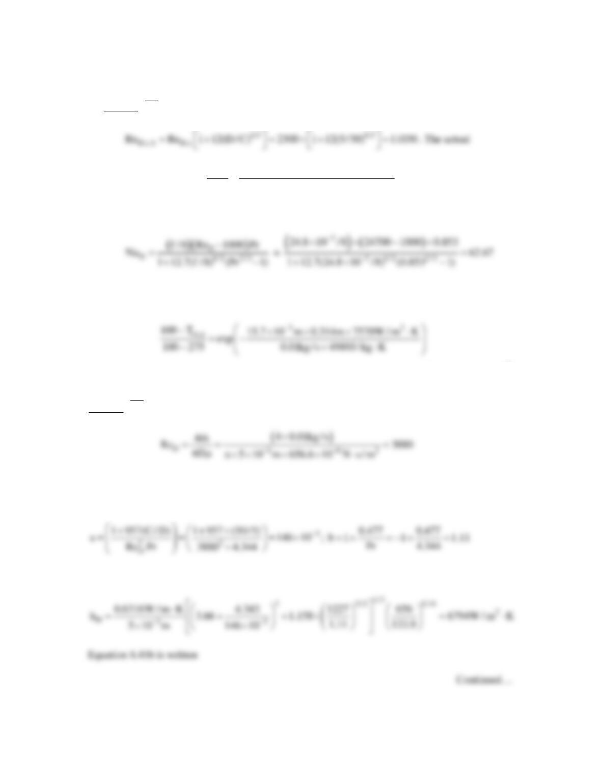
The Reynolds number is
Using Equation 8.57,
Therefore, hD = NuDk/D = 10.57× 0.6316 W/m∙K/5 × 10-3m = 1335 W/m2∙K. Equation 8.41b
PROBLEM 8.80 (Cont.)
(b) Heating,
m
T 260 C.= ° The critical Reynolds number is
Reynolds number is
D3 62
4m 4 0.01kg / s
Re 24700
D5 10 m 103.1 10 N s / m
−−
×
= = =
πm π× × × × ⋅
and the flow is
turbulent. Using the Gnielinski correlation, with f = (0.790lnReD – 1.64)-2 = (0.790 ln24700 –
1.64)-2 = 24.8 × 10⁻³,
Therefore, hD = NuDk/D = 62.67 × 0.6038 W/m∙K/5 × 10-3m = 7570 W/m2∙K. For P = 15.7 × 10⁻³
m, L = 2πC = 2 × π × 50 × 10-3 m = 0.314 m, and
m
=0.01 kg/s, Equation 8.41b is written as
from which Tm,o = 182.8°C. Then, qh = 0.02 kg/s × 4989 J/kg∙K × (182.8°C – 275°C) = 9197 W <
Cooling,
m
T 40 C.= °
The Reynolds number is
Since ReD < ReD,c,h, the flow is laminar and ReD(D/C)1/2 = 3880 ×(5/50)1/2 = 1227. The values of a
and b for use in Equation 8.76 are
Equation 8.76 is rearranged to yield
PROBLEM 8.80 (Cont.)
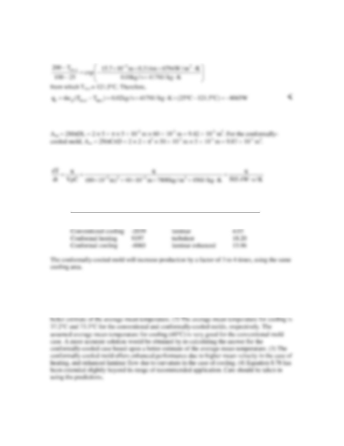
(c) For the conventional mold,
The time rate of change of the mold temperature is
The results are summarized in the following table.
Mold Type q (W) Flow Regime dT/dt (K/s)
Conventional heating 3190 turbulent 6.51
COMMENTS: (1) The average mean temperature for heating is 258.8°C and 230°C for the
conventional and conformally–cooled molds, respectively. The assumed average mean
temperature (260°C) is very good for the conventional mold case. A more accurate solution
would be obtained by re-calculating the answer for the conformally-cooled case based upon a