Problem 8.92
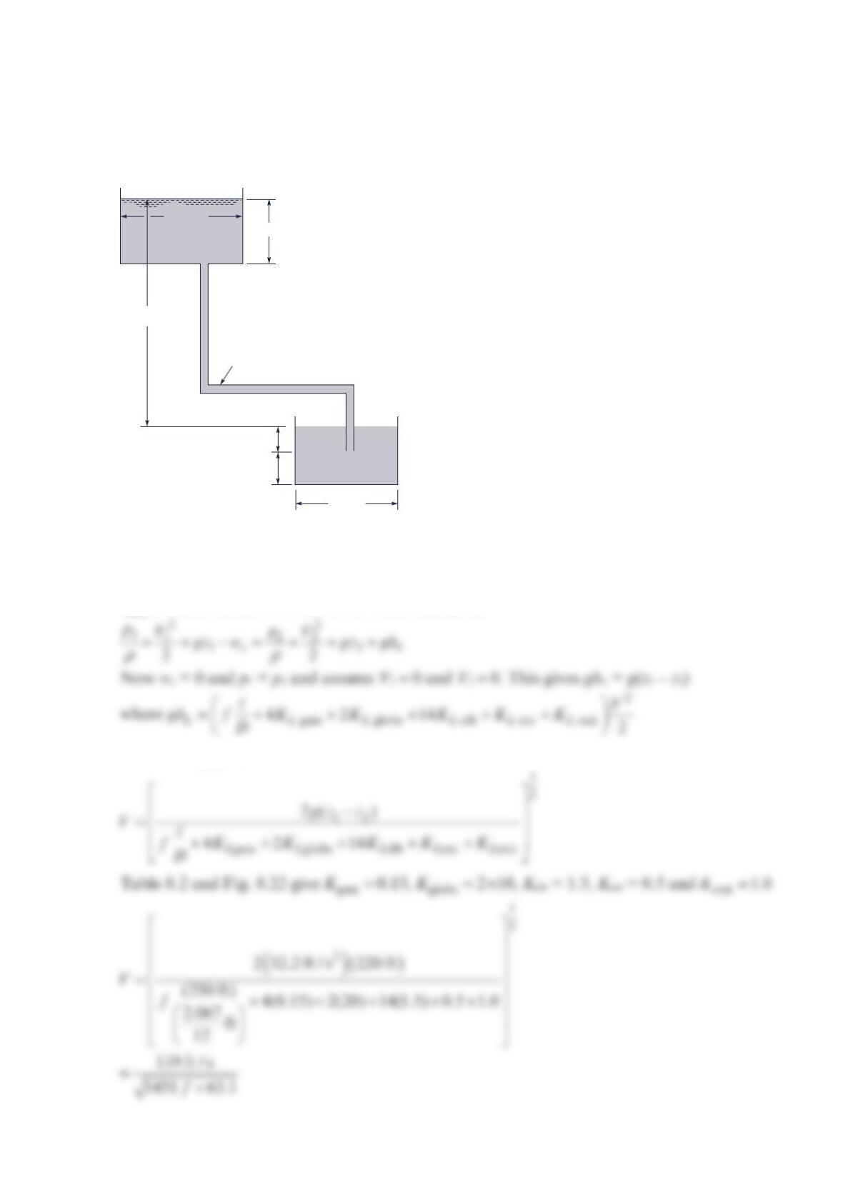
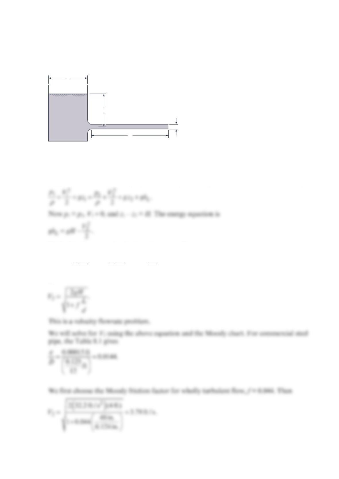
Calculate the water flowrate in the system shown in the figure below. The piping system
includes four gate valves, two half-open globe valves, fourteen 90° regular elbows, and 250
ft of 2-in. schedule 40 commercial steel pipe (with an actual inside diameter of 2.067 in.).
Assume threaded connections and a square-edged pipe entrance.
Solution 8.92
Assume steady state, and constant density. Apply the mechanical energy equation from the
upper water surface 1 to the lower water surface 2,
Substituting gives
220 ft
60 ft
Piping system
144 ft2
72 ft2
20 ft
30 ft
The velocity V must be found by trial and error. Assuming wholly turbulent, the Moody
chart gives f = 0.019 so
119 ft / s 12.5 ft / s,
1451(0.019) 63.1
V
==
+
and
V
and
()
()
45
Re 1.42 10 s /ft 12.3ft/ s 1.75 10=× =×
The Moody chart gives f = 0.0207 so convergence is obtained and
Problem 8.93
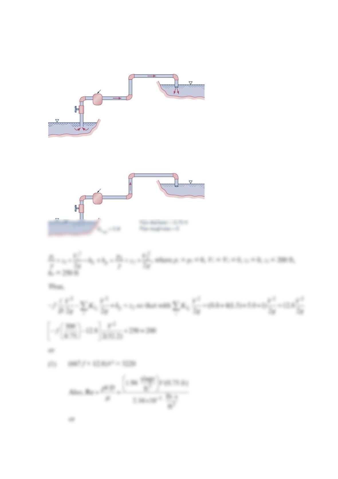
The pump shown in the figure below delivers a head of 250 ft to the water. Determine
the power that the pump adds to the water. The difference in elevation of the two ponds
is 200 ft.
Solution 8.93
K
L
valve
= 5.0
K
L
elbow
= 1.5
Pipe length = 500 ft
Pipe diameter = 0.75 ft
Pipe roughness = 0
K
L
ent
= 0.8
K
L
exit
= 1.0
Pump
K
L
valve
= 5.0
K
L
elbow
= 1.5
V
Pipe length = 500 ft
K
L
exit
= 1.0
Pump
(2)
•
(2) Re = 6.22 ×10⁴V
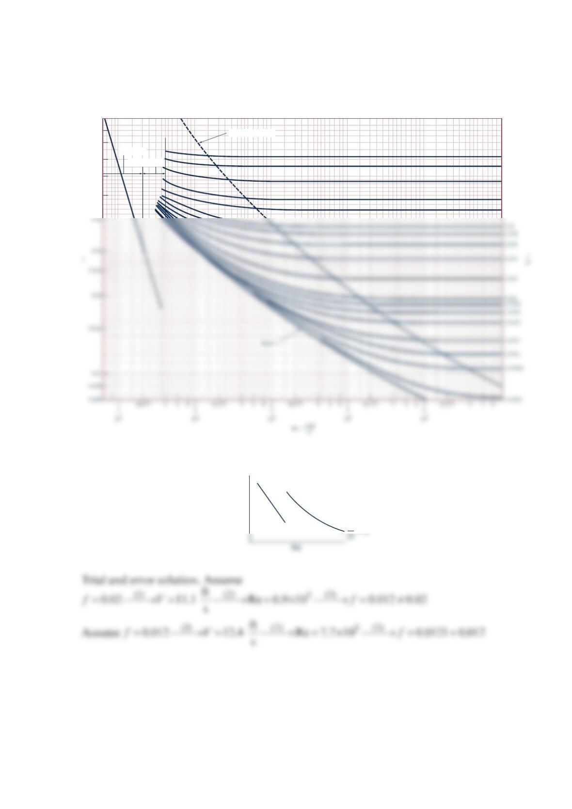
And from the figure below:
(1)
Transition range
Laminar flow
Wholly turbulent flow
0.1
0.09
0.08
0.07
0.06
0.05
0.05
0.04
0.03
0.02
0.015
f
ε
Thus, ft
12.4 s
V= and
Alternatively, we could replace Eq. (3) (the Moody chart) by equation
12.51
2.0 log 3.7 Re
D
ff
ε
=− +
(the Colebrook equation) and obtain
V
as follows.
From Eq. (1),
(3) 12.51
2.0 log Reff
=−
By combining Eqs. (4) and (5), we obtain a single equation involving only f:
Problem 8.94
For the standpipe system shown in the figure below, calculate the flowrate for H = 4.0 ft, D
= 6.77 in., d = 0.125 in., and L = 48 in. The fluid is 70°F water. Assume steady flow and
neglect the energy loss in the entrance nozzle. The pipe is commercial steel.
Solution 8.94
Apply the mechanical energy equation from point 1 to point 2. Assume constant density.
Neglecting the energy loss in the entrance nozzle,
222
222
,
,
222
L
VVV
LL
gh f f gH
dd
==−
or
D
H
Ld
(2)
(1)
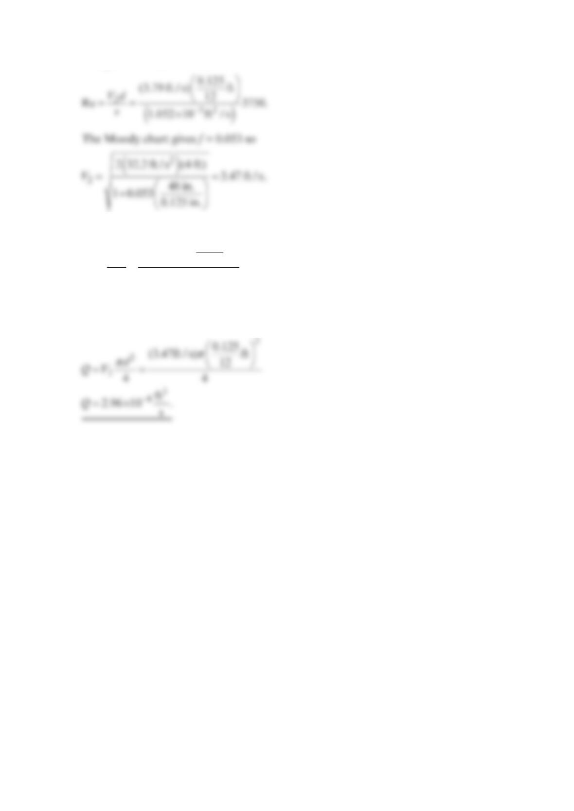
Using Table B.1, v = 1.052 × 10⁻⁵ ft2/s and
Then
()
2
52
0.125
(3.47 ft / s) ft
12
Re 3436.
1.052 10 ft / s
Vd
v−
==
×
And the Moody chart gives f = 0.054
Another iteration indicates convergence has been obtained,
Problem 8.95
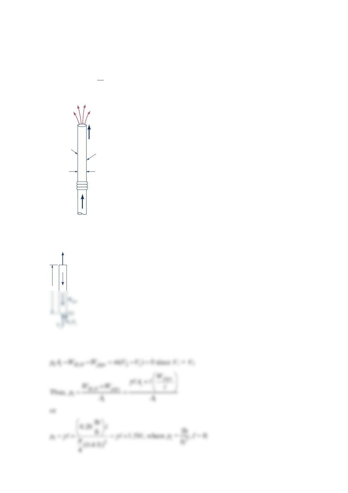
Water flows through two sections of the vertical pipe shown in the figure below. The
bellows connection cannot support any force in the vertical direction. The 0.4-ft-diameter
pipe weighs lb
0.2 ft , and the friction factor is assumed to be 0.02. At what velocity will the
force, F, required to hold the pipe be zero?
Solution 8.95
From the momentum equation applied to the control volume indicated
F
V
Free jet
f
= 0.020 Pipe weighs
0.20 lb/ft
Bellows
D
= 0.40 ft
(2)
W
H2O
V
2
Also,
22
2
11 2 2
12
222
pV p V V
zzf
ggDg
γγ
++=+++
, where p2 = 0, V1 = V2 = V, z1 = 0, and z2 = ℓ
Thus,
Problem 8.96
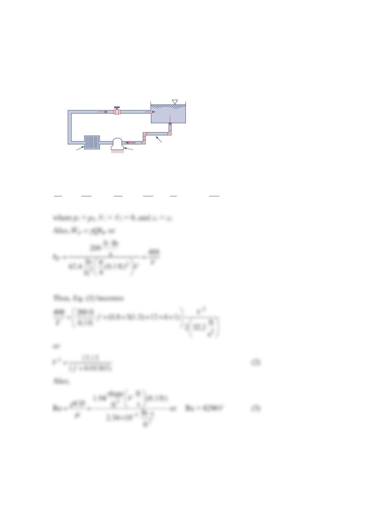
Water is circulated from a large tank, through a filter, and back to the tank as shown in the
figure below. The power added to the water by the pump is 200 ft ∙ lb/s. Determine the
flowrate through the filter.
Solution 8.96
++ + = + + + +
22 2
11 2 2
12
22 2
l
PL
i
pV p V V
zh z fK
ggDg
γγ
(1)
Pump
Filter
KL
elbow = 1.5
KL
exit = 1.0
KL
ent = 0.8
KL
valve = 6.0
KL
filter = 12.0
200 ft. of 0.1-ft-diameter
pipe with
ε
/
D
= 0.01
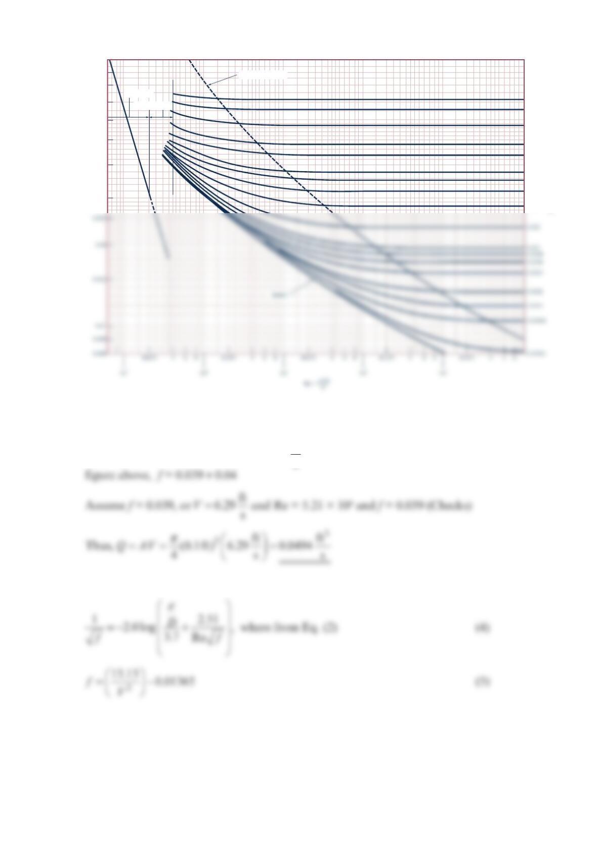
Trial and error solution:
Assume f = 0.04. From Eq. (2), ft
6.26 s
V
=; from Eq. (3), Re = 5.20 × 10⁴. Thus, from the
Alternatively, the Colebrook equation could be used rather than the Moody chart. Thus,
Transition range
Laminar flow
Wholly turbulent flow
0.1
0.09
0.08
0.07
0.06
0.05
0.04
0.03
0.05
0.04
0.03
0.02
0.015
0.01
0.008
0.006
0.004
_
_
D
ε
f