PROBLEM 8.25
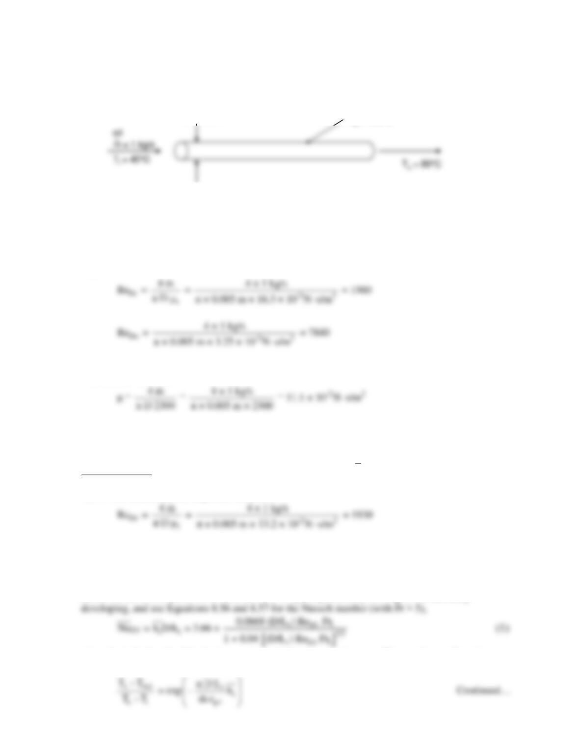
KNOWN: Oil flow rate. Pipe diameter. Inlet, outlet, and pipe surface temperatures.
FIND: Length of tube required to achieve desired outlet temperature.
SCHEMATIC:
ASSUMPTIONS: (1) Steady–state, (2) Incompressible flow, (3) Negligible viscous dissipation.
PROPERTIES: Table A-5, Engine oil (Ti = 45°C = 318 K): μi = 16.3 × 10⁻² N∙s/m2; (To = 80°C =
353 K): μo = 3.25 × 10⁻² N∙s/m2.
ANALYSIS: We begin by calculating the Reynolds numbers at the inlet and outlet, from Equation
8.6,
Therefore the flow is laminar at the inlet and turbulent at the outlet. The transition occurs when ReD
= 2300, that is, where
From Table A-5, this occurs at a transition temperature of Tm,t = 325 K = 52°C. Now we proceed to
analyze separately the heat transfer in the laminar and turbulent regions.
Laminar Region. The mean temperature in the laminar region is
m1
T
= (45°C + 52°C)/2 = 48.5°C =
321.5 K. The properties are cp1 = 1999 J/kg∙K, μ1 = 13.2 × 10⁻² N∙s/m2, k1 = 0.143 W/m∙K, Pr1 =
1851. We recalculate the Reynolds number,
The hydrodynamic and thermal entry lengths are given by
fd,h Di
x = 0.05 Re D = 0.05 × 1930 × 0.005 m = 0.48 m
fd,t fd,h i
x = x Pr = 0.48 m × 1851 = 890 m⋅
Based on this information, we assume the flow is hydrodynamically developed but thermally
where L1 is the length of the laminar region, which is as yet unknown. We can also use Equation
8.41b for the mean temperature variation:
D = 5 mm
Ts= 150°C
D = 5 mm
Ts= 150°C
PROBLEM 8.25 (Cont.)
Solving for
1
h
L1, we have
We can solve by iterating between Equations (1) and (2). Beginning with the estimate
D1
Nu = 3.66,
D1
D1
Turbulent Range. The mean temperature in the turbulent region is
m2
T
= (52°C + 80°C)/2 = 66°C =
339 K. The properties are cp2 = 2072 J/kg∙K, μ2 = 5.62 × 10⁻² N∙s/m2, k2 = 0.139 W/m∙K, Pr2 = 834.
where from Equation 8.21,
f = (0.790 ln ReD2 – 1.64)-2 = (0.790 ln (4530) – 1.64)-2 = 0.0398
and h2 = NuD2k2/D = 5120 W/m2 ∙K. Then the required length L2 can be found from Equation 8.41b,
expressed between the transition point and the outlet,
The total required length is L = L1 + L2 = 26.8 m. <
COMMENTS: (1) If we had simply calculated the properties based on the mean temperature of
m
T
=
PROBLEM 8.26
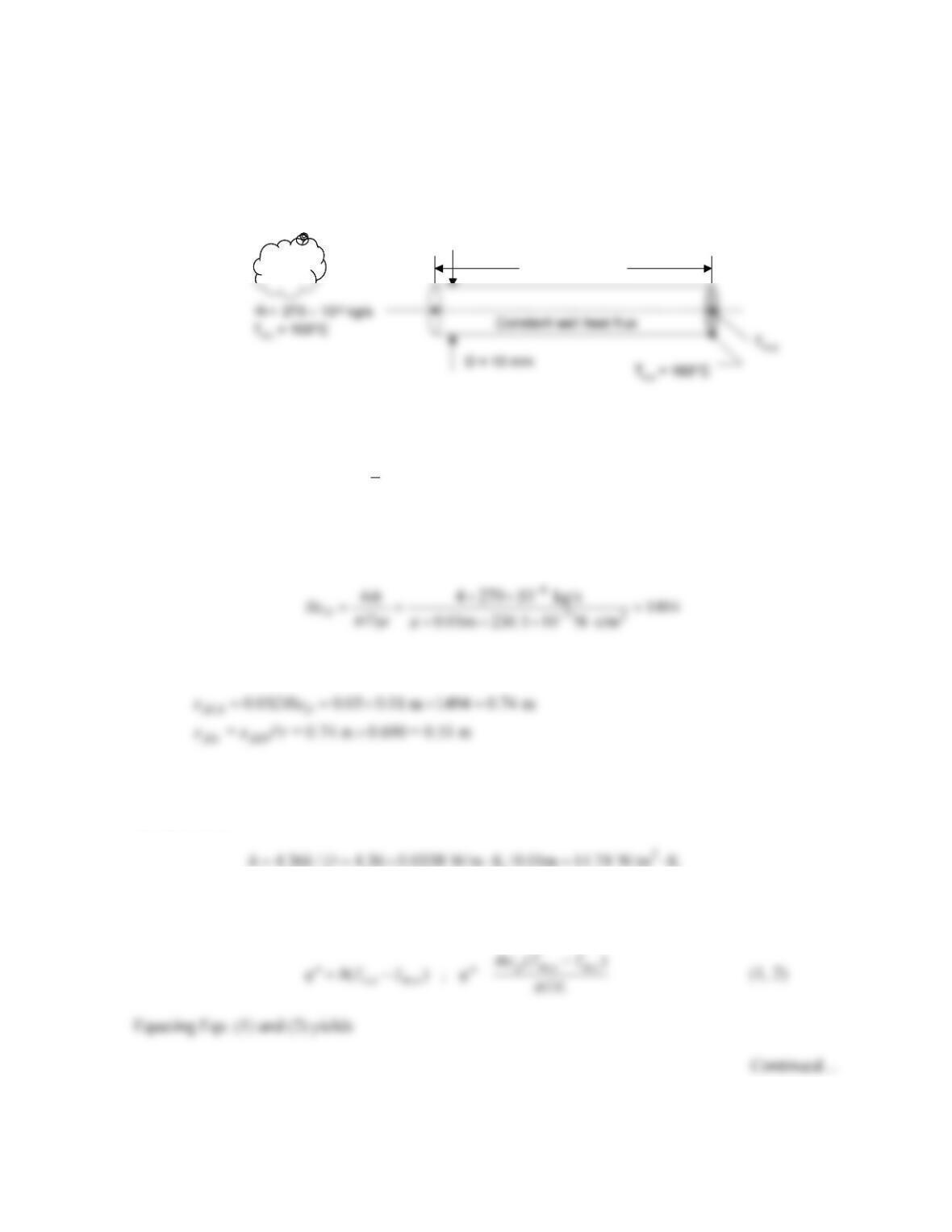
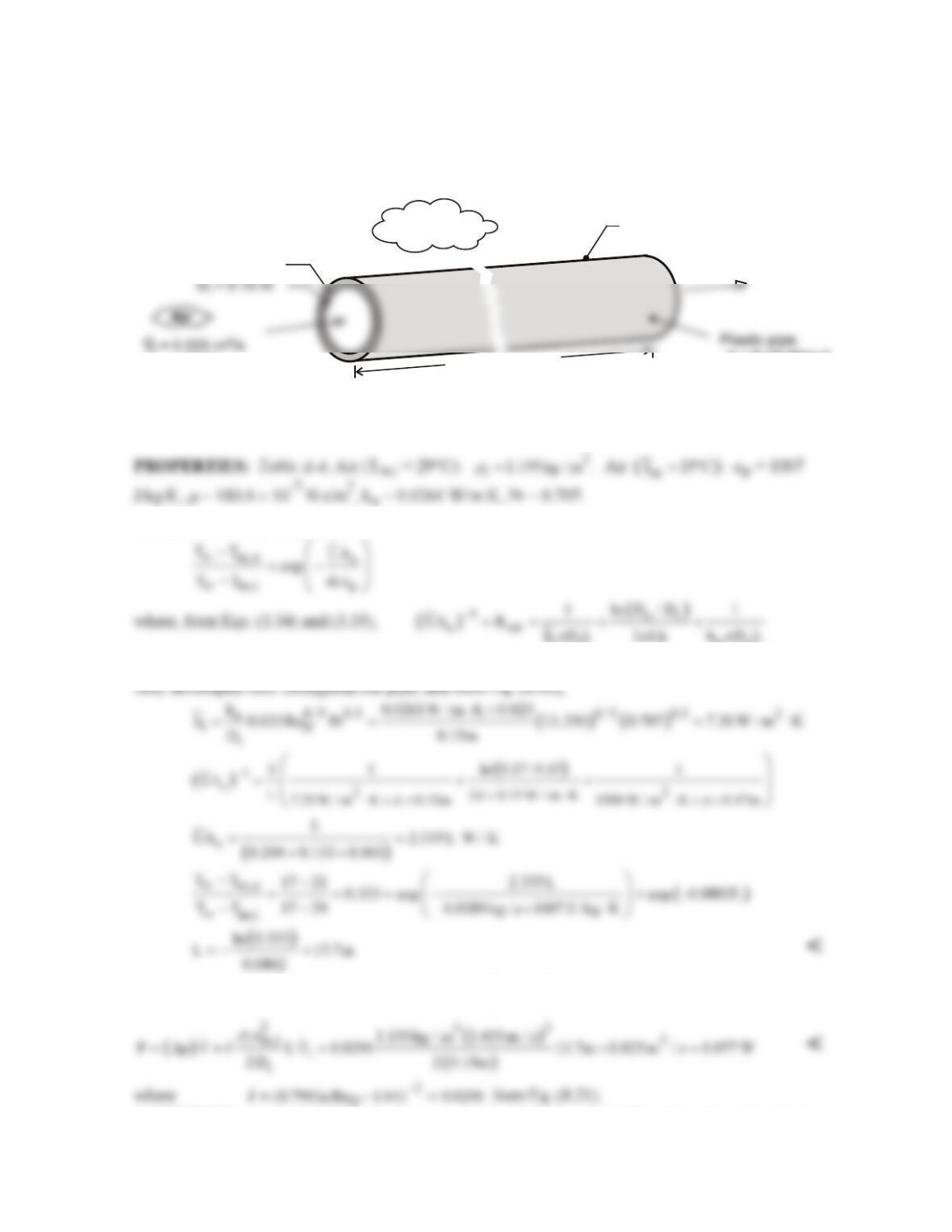
KNOWN: Diameter and length of tube, air flow rate, air temperature and pressure at the tube inlet.
Surface temperature at the tube exit.
FIND: (a) The heat transfer rate of the problem. (b) Conditions at the tube exit for reduced tube
length. (c) Conditions at the tube exit for increased air flow rate.
SCHEMATIC:
ASSUMPTIONS: (1) Steady–state conditions, (2) Constant properties, (3) Negligible viscous
dissipation.
PROPERTIES: Table A.4, Air (
m
T
≈ 400 K, p = 1 atm):
m
= 230.1×10⁻⁷ N⋅s/m2, Pr = 0.690, k =
0.0338 W/m⋅K, cp = 1014 J/kg⋅K.
ANALYSIS: (a) We begin by calculating the Reynolds number
Therefore, the flow is laminar. The hydrodynamic and thermal entrance lengths are
Therefore, the flow is fully-developed at the tube exit. For fully–developed laminar flow with constant
heat flux conditions, the Nusselt number is NuD = 4.36. Therefore, the local heat transfer coefficient at
the tube exit is
Two independent expressions for the heat flux may be written based upon application of Newton’s law
of cooling at the tube exit and an overall energy balance.
Air
L = 2 m
AirAir
L = 2 m
PROBLEM 8.26 (Cont.)
= 146.3°C
Hence, the heat rate is
(c) If the flow rate is increased by an order of magnitude, the Reynolds number will increase to ReD =
14,940, and the flow will be turbulent at the tube exit. Since L/D = 2 m / 0.01 m = 200, the turbulent
flow at the tube exit will also be fully developed. The heat transfer coefficient at the tube exit would
exceed that of part (a).
COMMENTS: In part (b), the local heat transfer coefficient would exceed h = 14.74 W/m2 at the
tube exit and could be estimated using Fig. 8.10a. Specifically, for Gz-1 = (x/D)/(ReDPr) = (0.2 m/ 0.01
PROBLEM 8.27
KNOWN: Thermal conductivity and inner and outer diameters of plastic pipe. Volumetric flow rate and inlet
and outlet temperatures of air flow through pipe. Convection coefficient and temperature of water.
FIND: Pipe length and fan power requirement.
SCHEMATIC:
k = 0.15 W/m-K
L
Water
T = 17 C
o
oo
TC
m,o o
= 21
h
o
= 1500 W/m -K
2
i
m,i o
T = 29 C
D
o
= 0.17 m
ASSUMPTIONS: (1) Steady-state, (2) Negligible heat transfer from air in vertical legs of pipe, (3)
Ideal gas with negligible viscous dissipation and pressure variation, (4) Smooth interior surface, (5)
Constant properties.
ANALYSIS: From Eq. (8.45a)
ii oo
With
ii
m 0.0289 kg / s
ρ
= ∀=
and
Di
Re 4m / D 13, 350,
πm
= =
flow in the pipe is turbulent. Assuming
From Eqs. (8.22a) and (8.22b) and with
( )
2
m,i i i
u / D / 4 1.415 m / s,
π
=∀=
the fan power is
COMMENTS: (1) With L/Di = 91, the assumption of fully developed flow throughout the pipe is
justified. (2) The fan power requirement is small, and the process is economical. (3) The resistance
to heat transfer associated with convection at the outer surface is negligible.
PROBLEM 8.28
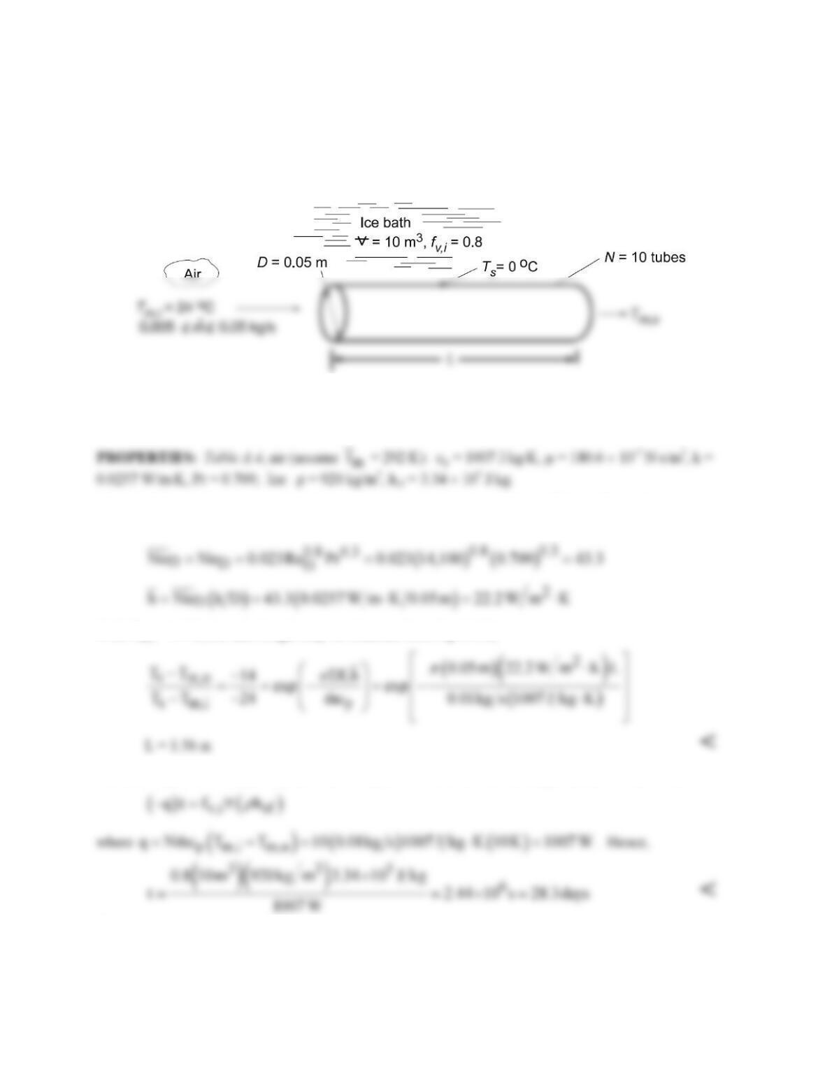
KNOWN: Diameter and surface temperature of ten tubes in an ice bath. Inlet temperature and flowrate
per tube. Volume (∀) of container and initial volume fraction, fv,i, of ice.
FIND: (a) Tube length required to achieve a prescribed air outlet temperature Tm,o and time to
completely melt the ice, (b) Effect of mass flowrate on Tm,o and suitable design and operating conditions.
SCHEMATIC:
ASSUMPTIONS: (1) Steady-state, (2) Ideal gas with negligible viscous dissipation and pressure
variation, (3) Constant properties, (4) Fully developed flow throughout each tube, (5) Negligible tube
wall thermal resistance.
ANALYSIS: (a) With ReD = 4
m
/πDm = 4(0.01 kg/s)/π(0.05 m)180.6 × 10⁻⁷ N⋅s/m2 = 14,100 for
m
=
0.01 kg/s, the flow is turbulent, and from Eq. 8.60,
With Tm,o = 14°C, the tube length may be obtained from Eq. 8.41b,
The time required to completely melt the ice may be obtained from an energy balance of the form,
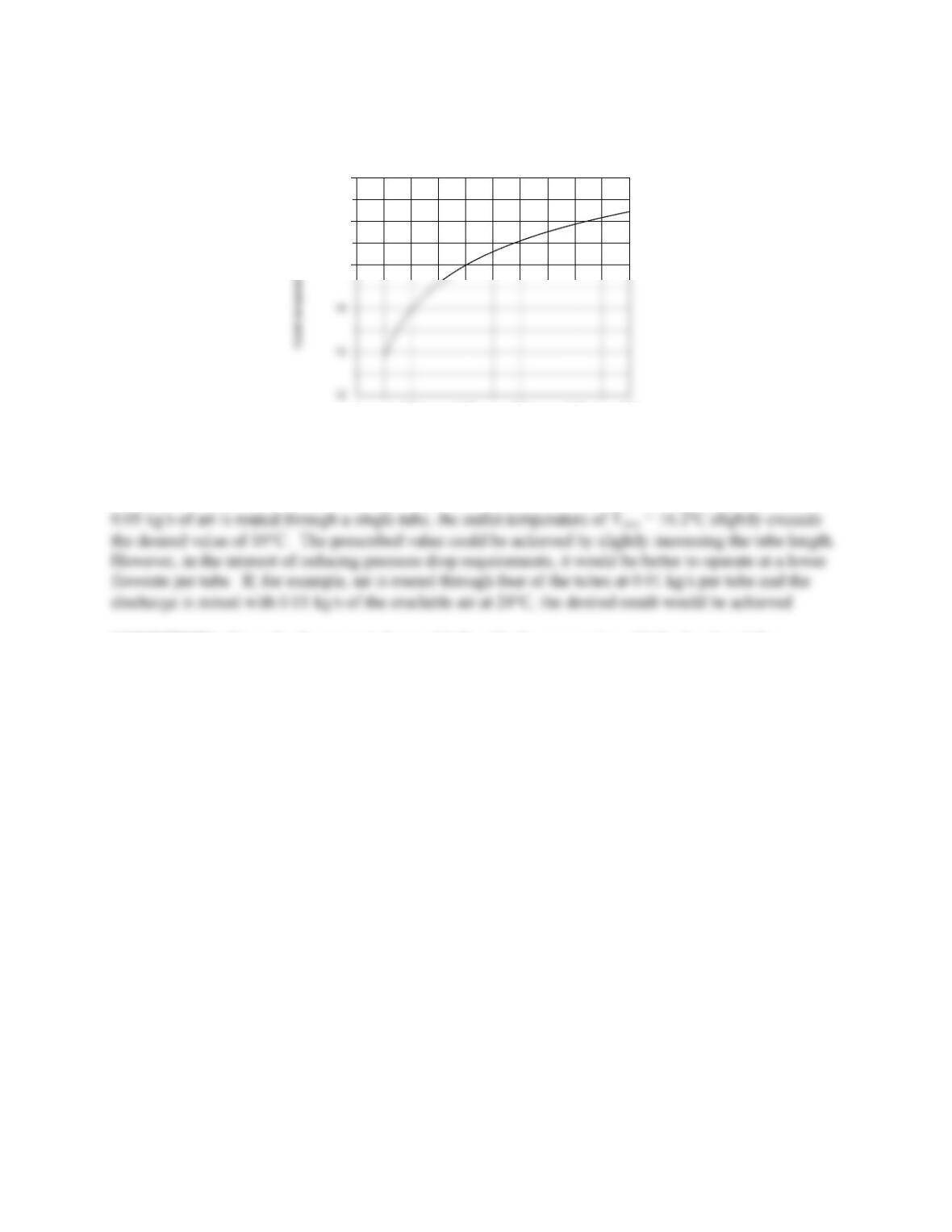
(b) Using the appropriate IHT Correlations and Properties Tool Pads, the following results were
obtained.
Continued…
PROBLEM 8.28 (Cont.)
00.01 0.02 0.03 0.04 0.05
Mass flowrate per tube, mdot(kg/s)
15
16
17
Although heat extraction from the air passing through each tube increases with increasing flowrate, the
increase is not in proportion to the change in
m
and the temperature difference (Tm,i – Tm,o ) decreases. If
COMMENTS: Since the flow is turbulent and L/D = 31, the assumption of fully developed flow
throughout a tube is marginal and the foregoing analysis overestimates the discharge temperature.
PROBLEM 8.29
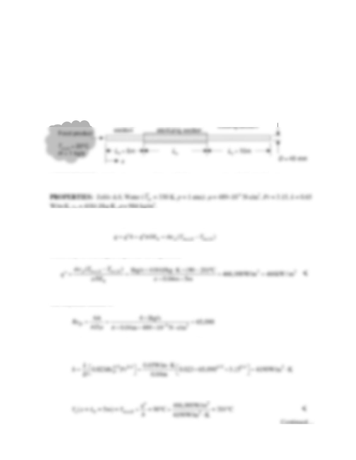
KNOWN: Initial food temperature and mass flow rate. Length of heating and cooling sections in a
food sterilizer. Diameter of sterilizer tube. Time-at-temperature constraint, and constraint on local
maximum food temperature.
FIND: (a) Heat flux in the heating section. (b) Maximum local product temperature and its location.
(c) Minimum required sterilizing section length. (d) Sketch of the axial distributions of the mean,
surface, and centerline food temperatures from entrance to exit of sterilizer.
SCHEMATIC:
ASSUMPTIONS: (1) Steady-state conditions, (2) Constant properties, (3) Negligible viscous
dissipation.
W/m⋅K, cp = 4184 J/kg⋅K,
ρ
= 984 kg/m3.
ANALYSIS: (a) An energy balance applied to the heating section yields
which may be rearranged to provide the expression
(b) The maximum local product temperature occurs at the tube wall at the end of the heating section.
The Reynolds number is
Hence, the flow is turbulent. Since Lh/D = 5m/0.04m = 125, the flow is fully-developed. Using the
Dittus-Boelter correlation,
From Newton’s law of cooling,
Heating
Insulated
PROBLEM 8.29 (Cont.)
The second constraint is satisfied. <
(c) The minimum length of the sterilizing section is
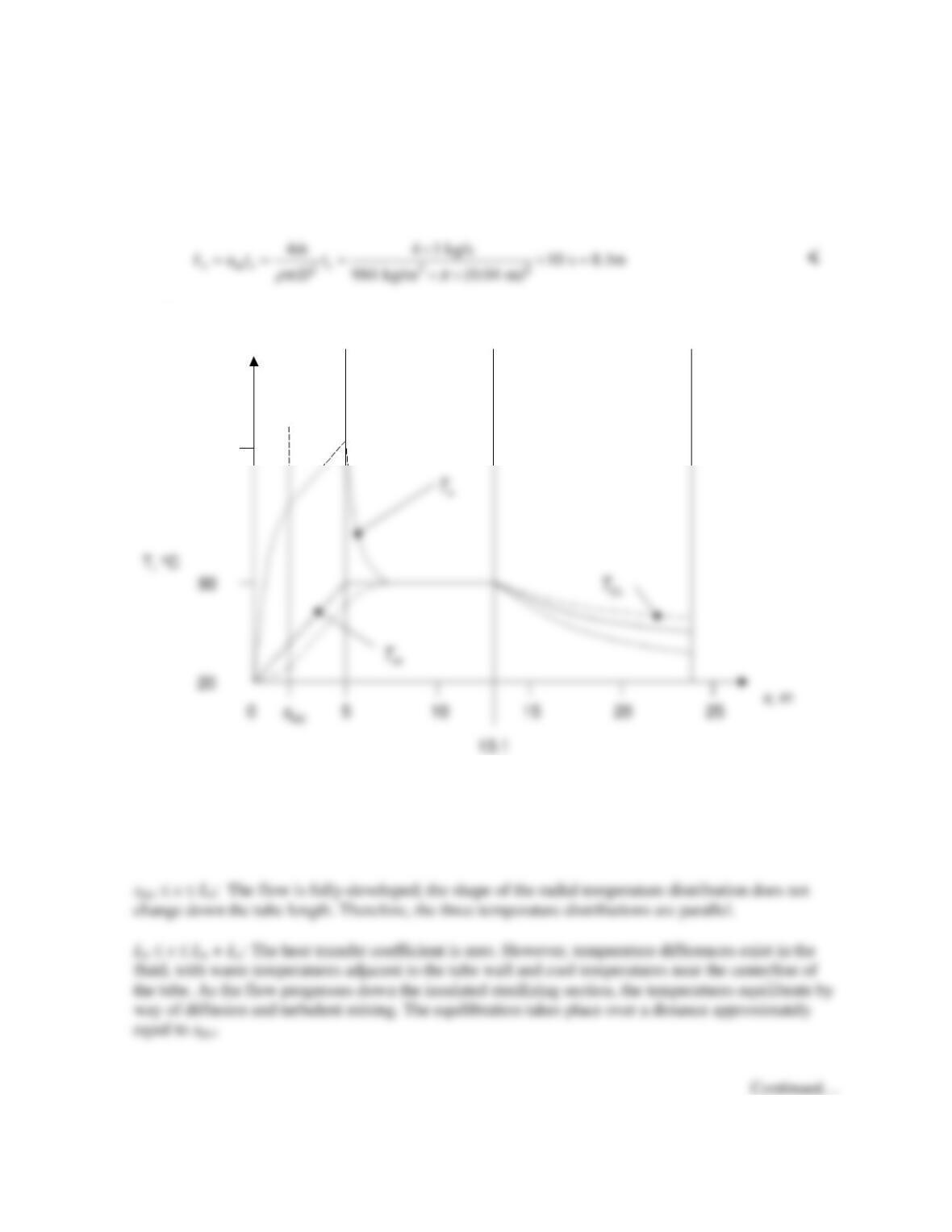
(d) The axial distributions of the mean, surface, and centerline temperatures are shown below.
Important features of the temperature distribution are as follows.
0 x xfd,t: Near the tube entrance, the heat transfer coefficient is theoretically infinite, and all three
temperatures are nearly the same value.
200
Cooling sectionInsulated
sterilizing
section
Heating
section

PROBLEM 8.29 (Cont.)
Lh + Ls x Lh + Ls + Lc: The fluid is cooled. Hence, the warmest temperature fluid is at the
COMMENTS: (1) The velocity of the fluid at the centerline exceeds velocities at any other radial
location. Hence, the fluid at the centerline of the tube will not satisfy the time-at-temperature criterion.
Therefore, use of a coiled tube or other heat transfer enhancement devices (Section 8.7) would be
appropriate in this application. (2) The insulation thickness in the sterilizing section should be much
greater than the critical insulation thickness.
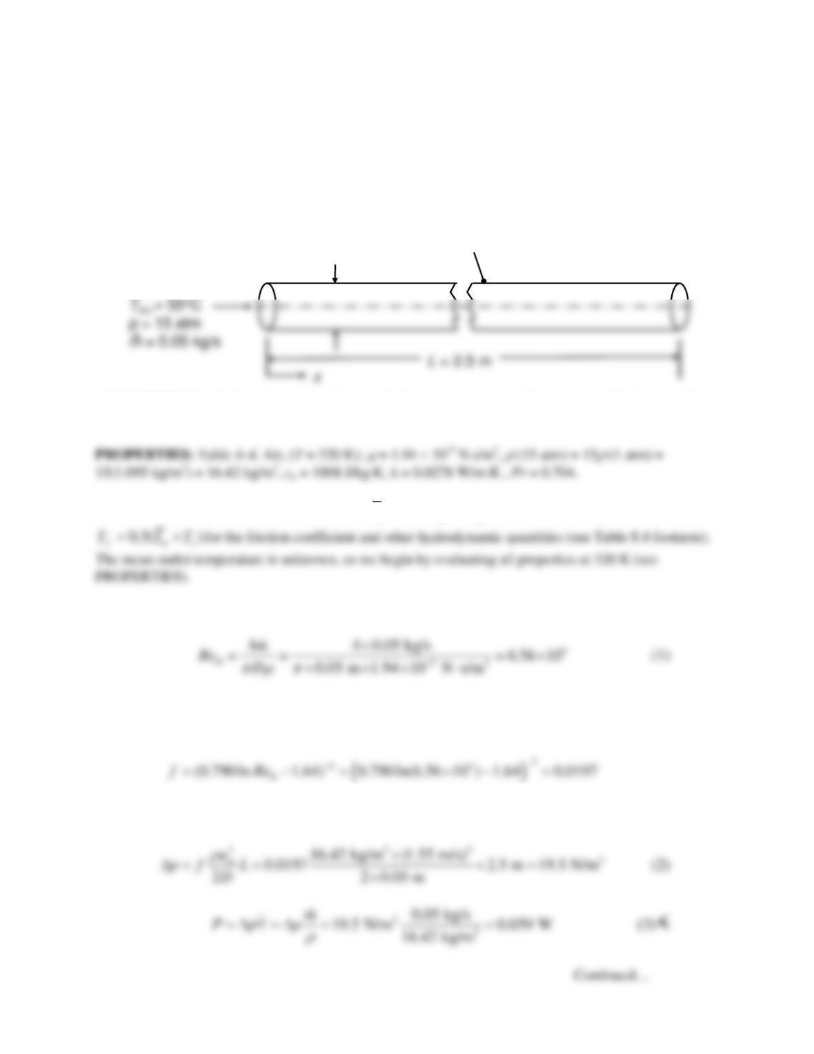
PROBLEM 8.30
KNOWN: Mass flow rate, pressure, and inlet temperature of dry, compressed air. Diameter, length, and
surface temperature of tube.
FIND: (a) Outlet mean temperature, heat transfer rate, and pumping power for 50–mm-diameter tube. (b)
Required tube length and pumping power for 40-mm–diameter tube to achieve the same heat transfer rate
as 50–mm–diameter tube.
SCHEMATIC:
D= 50 mm
Dry air
T
s
= 25°C
ASSUMPTIONS: (1) Steady-state conditions, (2) Constant properties, (3) Incompressible liquid with
negligible viscous dissipation.
ANALYSIS: Properties must be evaluated at
,,
0.5( )
m mi mo
T TT= +
for heat transfer quantities, and at
(a) The Reynolds number is:
The flow is turbulent and it is fully developed since L/D > 10. The velocity is
2
/ ( / 4)
m
um D
ρπ
=
=
1.55 m/s. The friction coefficient can be found from Equation 8.21:
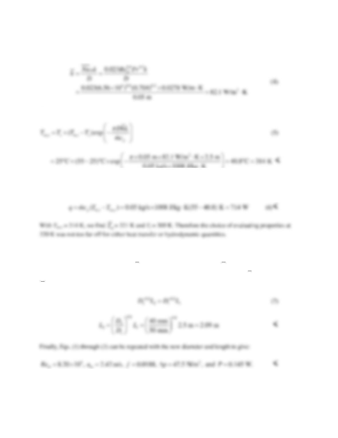
Then from Equations 8.22ab, the pressure drop and pumping power are:
PROBLEM 8.30 (Cont.)
The heat transfer coefficient can be found from the Dittus-Boelter equation, Equation 8.60, with n = 0.3
for Ts < Tm:
The mean outlet temperature can be found from Equation 8.41b:
0.05 kg/s 1008 J/kg K
×⋅
The heat transfer rate can be calculated from Equation 8.34 (with a change in sign to calculate heat
transfer from the air to the tube wall):
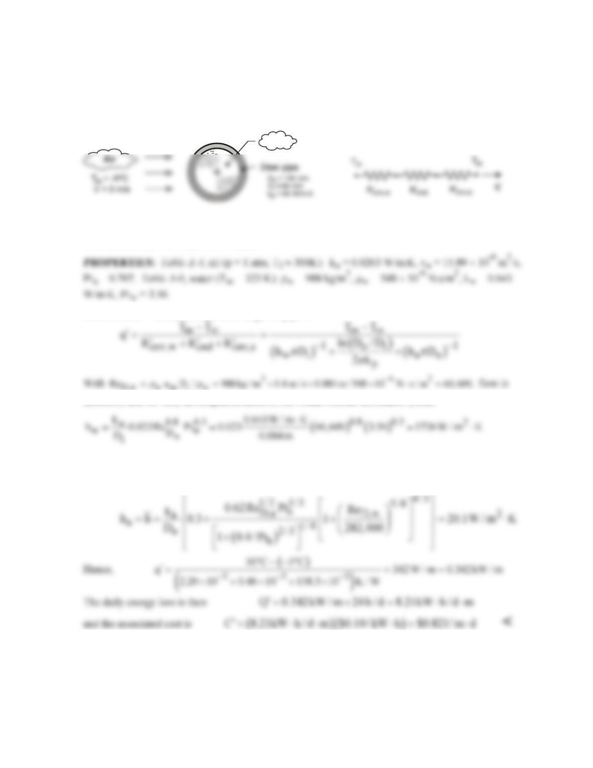
(b) We wish to achieve the same q when the diameter is reduced to 40 mm. From Eq. (6) it can
be seen that the outlet mean temperature must be the same. From Eq. (5), the same mean outlet
temperature will be achieved when
hDL
is the same (that is, the same
h
× surface area will achieve
the same heat transfer rate). From Eq. (4) and the fact that
1
~
D
Re D
−
(see Eq.(1)),
1.8
~,hD
−
therefore
0.8
~.hDL D L
−
Finally, we can relate the diameters and lengths for the two cases:
COMMENTS: (1) The use of the Dittus–Boelter correlation facilitated an analytical solution for L in part
(b). Use of the Sieder and Tate or Gnielinski correlation would yield similar results for L but less physical
insight. (2) In fully developed laminar flow, the Nusselt number is independent of D, therefore a change
in diameter doesn’t change the heat transfer rate. The same q would be achieved for the same length.
PROBLEM 8.31
KNOWN: Diameters and thermal conductivity of steel pipe. Temperature and velocity of water flow
in pipe. Temperature and velocity of air in cross flow over pipe. Cost of producing hot water.
FIND: Daily cost of heat loss per unit length of pipe.
SCHEMATIC:
ASSUMPTIONS: (1) Steady state, (2) Constant properties, (3) Negligible radiation from outer
surface, (4) Fully-developed flow in pipe.
ANALYSIS: The heat loss per unit length of pipe is
turbulent, and for fully developed conditions, the Dittus-Boelter correlation yields
With
( )
62
D,a o a
Re VD / 3 m / s 0.1m / 15.89 10 m / s 18, 880,
ν
−
==× ×=
the Churchill-Bernstein
correlation yields
COMMENTS: Because
cnv,a cnv,w
R R,
′′
>>
the convection resistance for the water side of the pipe
could have been neglected, with negligible error. The implication is that the temperature of the pipe’s
inner surface closely approximates that of the water. If
cnv,w
R′
is neglected, the heat loss is
q 346 W / m.
′=
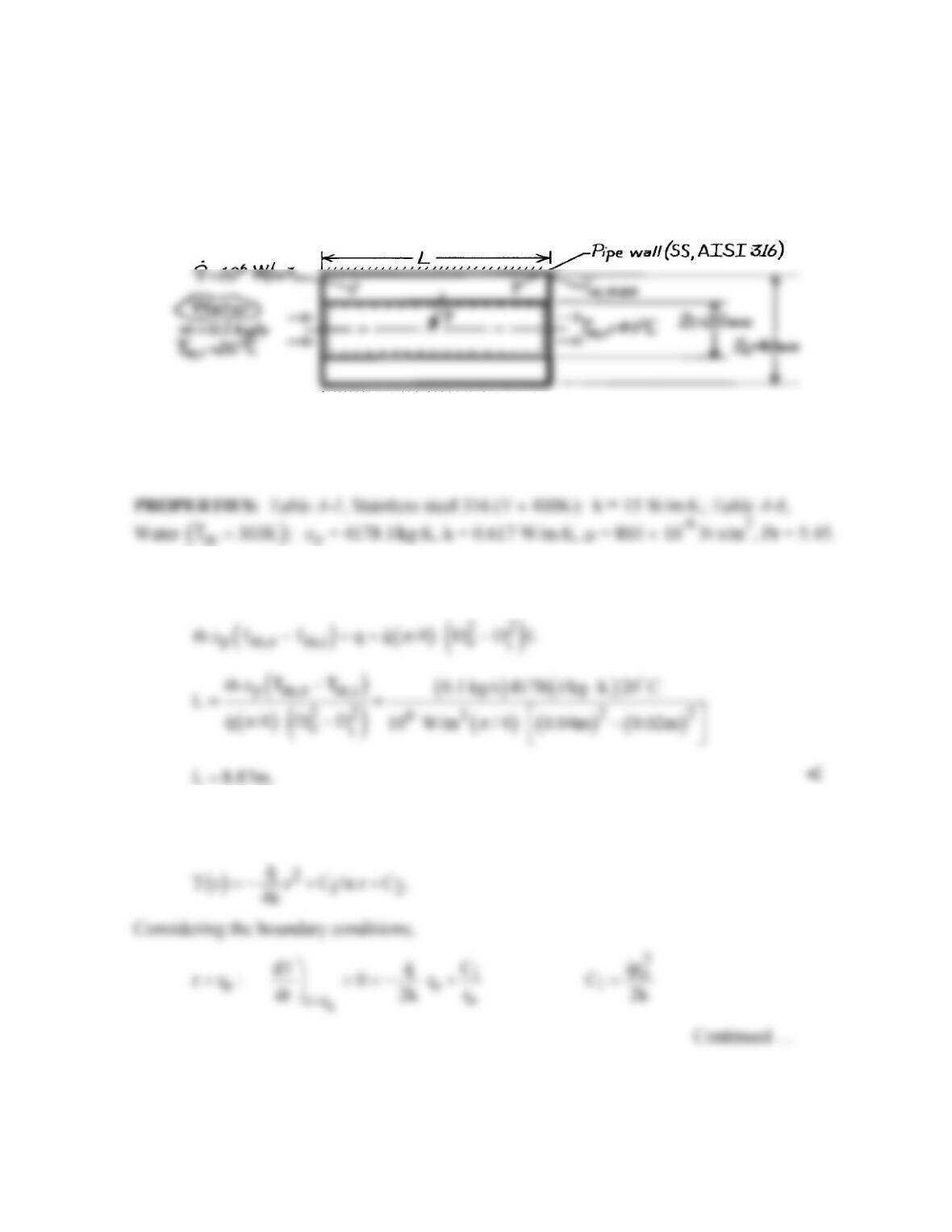
Water T C, u = 0.5 m/s
m om
= 50
u
m
= 0.4 m/s
PROBLEM 8.32
KNOWN: Inner and outer diameter of a steel pipe insulated on the outside and experiencing
uniform heat generation. Flow rate and inlet temperature of water flowing through the pipe.
FIND: (a) Pipe length required to achieve desired outlet temperature, (b) Location and value
of maximum pipe temperature.
SCHEMATIC:
ASSUMPTIONS: (1) Steady-state conditions, (2) Constant properties, (3) Incompressible
liquid with negligible viscous dissipation, (4) One-dimensional radial conduction in pipe wall,
(5) Outer surface is adiabatic.
ANALYSIS: (a) Performing an energy balance for a control volume about the inner tube, it
follows that
(b) The maximum wall temperature exists at the pipe exit (x = L) and the insulated surface (r
= ro). From Eq. 3.56, the radial temperature distribution in the wall is of the form
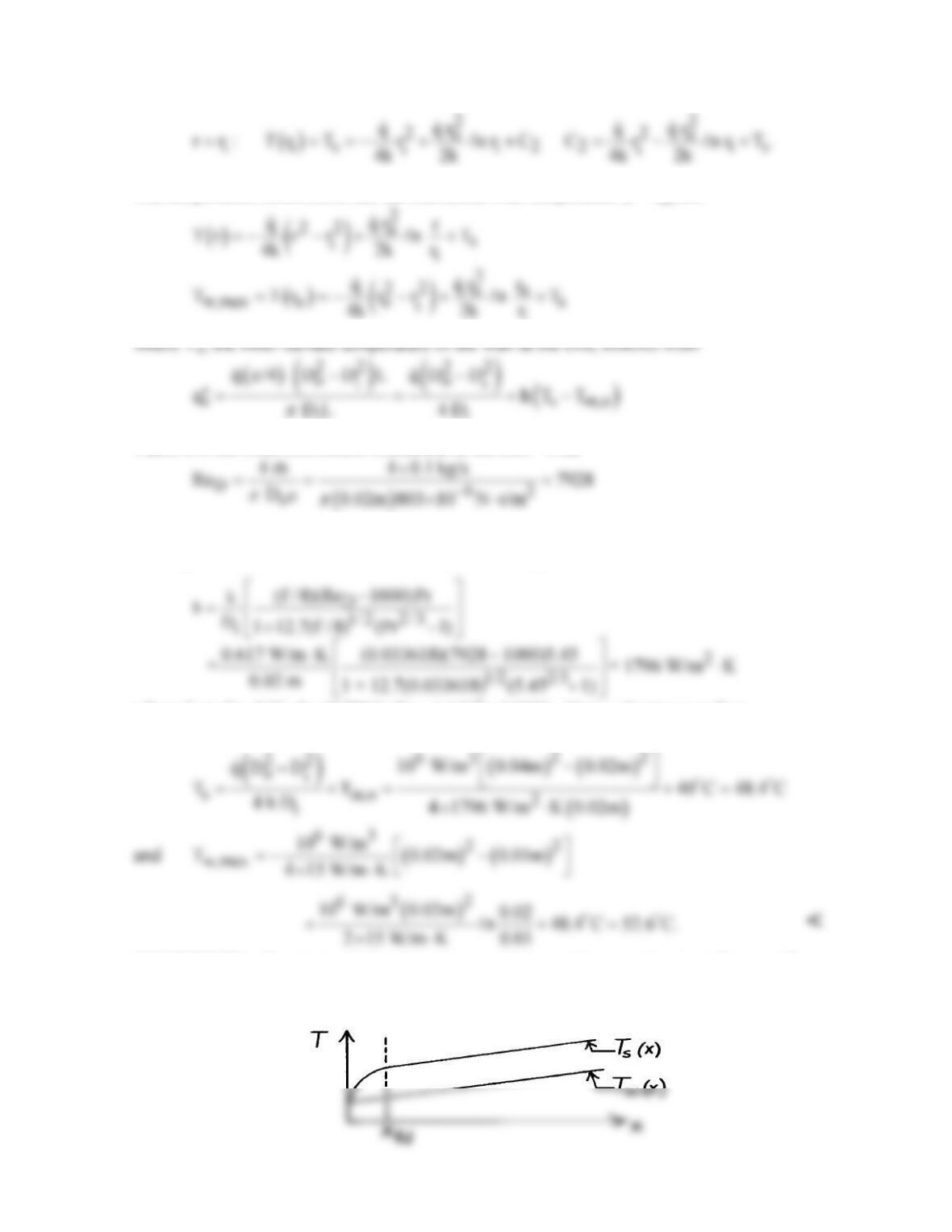
PROBLEM 8.32 (Cont.)
The temperature distribution and the maximum wall temperature (r = ro) are
ii
where h is the local convection coefficient at the exit. With
the flow is turbulent and, with (L/Di) = (8.87 m/0.02m) = 444 >> (xfd/D) ≈ 10, it is also fully
developed. Hence, from the Gnielinski correlation, Eq. 8.62,
where from Eq. 8.21, f = (0.790 ln ReD-1.64)–2 = 0.0336. Hence, the inner surface
temperature of the wall at the exit is
COMMENTS: The physical situation corresponds to a uniform surface heat flux, and Tm
increases linearly with x. In the fully developed region, Ts also increases linearly with x.
PROBLEM 8.33
KNOWN: Fully–developed conditions for laminar or turbulent flow characterized by a fixed mass
flow rate. Constant surface temperature conditions with Ts < Tm.
FIND: Determine whether a small or large diameter tube will be more effective in minimizing heat
loss from the flowing fluid.
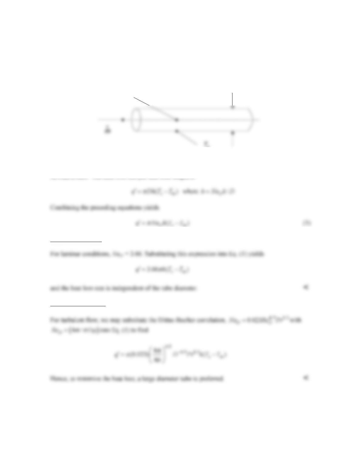
SCHEMATIC:
ASSUMPTIONS: (1) Fully-developed, (2) Constant properties, (3) Negligible viscous dissipation.
ANALYSIS: The heat loss rate per unit tube length is
Laminar Conditions
Turbulent Conditions
COMMENTS: The large diameter tube will result in reduced heat loss, but will be more expensive
relative to a small diameter tube. If the cool surface temperature is induced by heat losses to the
environment, a more effective approach to minimize heat loss would be to insulate the exterior of the
tube.
TmD
PROBLEM 8.34
KNOWN: Flow rate of NaK (56%/44%), NaK inlet and outlet temperatures, tube wall temperature,
tube diameter.
FIND: Tube length, and local convective flux at the tube exit.
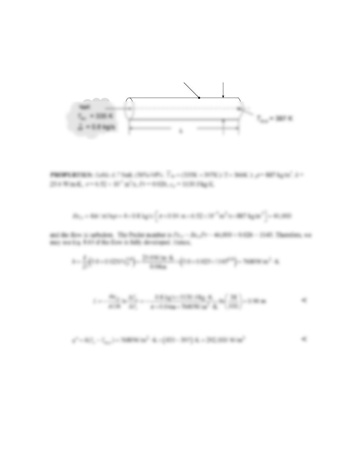
SCHEMATIC:
ASSUMPTIONS: (1) Constant properties, (2) Negligible viscous dissipation, (3) Fully developed
flow.
ANALYSIS: The Reynolds number is
The required tube length is, from Eq. 8.41a,
The local convective heat flux at x = L = 0.90 m is
COMMENTS: The dimensionless tube length is L/D = 0.90m/0.04m = 22.5. The flow is therefore
fully developed, and use of Eq. 8.65 is appropriate.
T
s
= 450 K
D = 50 mm
T
s
= 435 K D= 40 mm
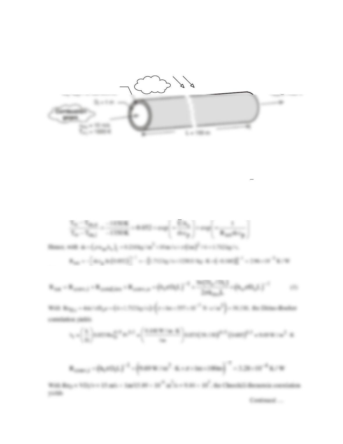
PROBLEM 8.35
KNOWN: Duct diameter and length. Thermal conductivity of insulation. Gas inlet temperature and
velocity and minimum allowable outlet temperature. Temperature and velocity of air in cross flow.
FIND: Minimum allowable insulation thickness.
SCHEMATIC:
Ambient
air T = 250 K
oo
V = 15 m/s
Insulation
ASSUMPTIONS: (1)Combustion gases are ideal with negligible viscous dissipation and pressure
variation, (2) Fully developed flow throughout duct, (3) Negligible duct wall conduction resistance,
(4) Negligible effect of insulation thickness on outer convection coefficient and thermal resistance,
(5) Properties of gas may be approximated as those of air.
PROPERTIES: Table A-4, air (p = 1 atm). Tm,i = 1600K: (
ρ
i = 0.218 kg/m3).
m
T
= (Tm,i +Tm,o)/2
= 1500K: (
ρ
= 0.232 kg/m3, cp = 1230 J/kg⋅K,
m
= 557 × 10-7 N⋅s/m2, k = 0.100 W/m⋅K, Pr = 0.685).
Tf ≈ 300K (assumed):
ν
= 15.89 × 10⁻⁶ m2/s, k = 0.0263 W/m⋅K, Pr = 0.707.
ANALYSIS: From Eq. (8.45b),
The total thermal resistance is
The internal resistance is then
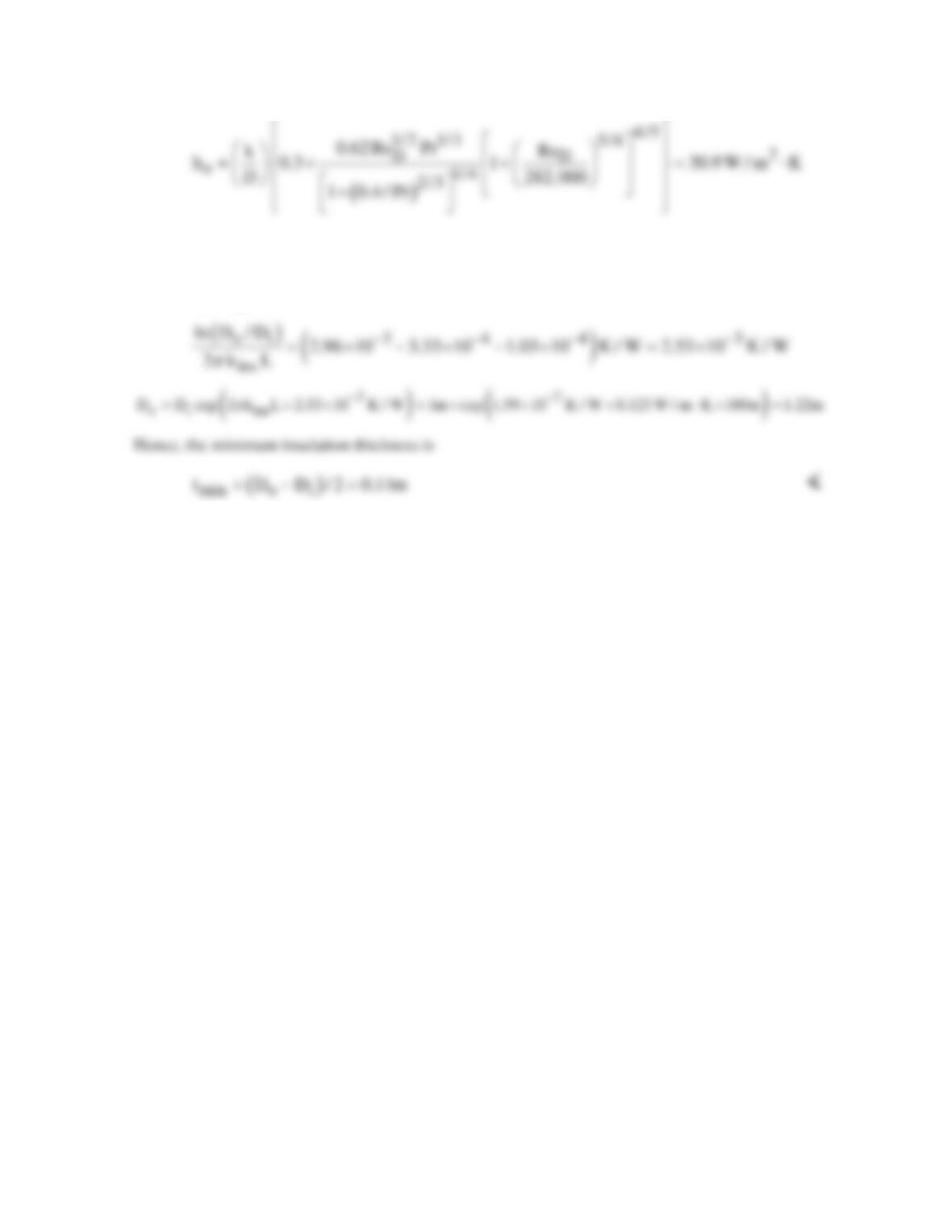
PROBLEM 8.35 (Cont.)
( )
()
1
124
conv,o o i
R h D L 30.9 W / m K 1m 100m 1.03 10 K / W
ππ
−
−−
≈ = ⋅×× × = ×
Hence, from Eq. (1)
COMMENTS: With Do = 1.22m, use of Di = 1m to evaluate the outer convection coefficient and
thermal resistance is a reasonable approximation. However, improved accuracy may be obtained by
using the calculated value of Do to determine conditions at the outer surface and iterating on the
solution.
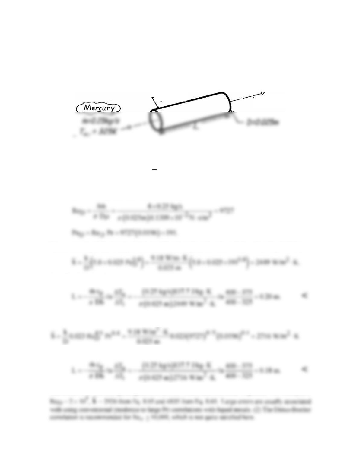
PROBLEM 8.36
KNOWN: Flow rate, inlet temperature and desired outlet temperature of liquid mercury flowing
through a tube of prescribed diameter and surface temperature.
FIND: Required tube length and error associated with use of a correlation for moderate to large Pr
fluids.
SCHEMATIC:
T
s
=400K T
m,o
=375K
ASSUMPTIONS: (1) Steady-state conditions, (2) Constant properties, (3)Incompressible liquid with
negligible viscous dissipation, (4) Fully developed flow.
PROPERTIES: Table A-5, Mercury
T K
m=350
cT:
cp = 137.7 J/kg⋅K, m = 0.1309 × 10⁻² N⋅s/m2,
k = 9.18 W/m⋅K, Pr = 0.0196.
ANALYSIS: The Reynolds and Peclet numbers are
Hence, assuming fully developed turbulent flow throughout the tube, it follows from Eq. 8.65 that
From Eq. 8.41a, it follows that
If the Dittus–Boelter correlation, Eq. 8.60, is used in place of Eq. 8.65,
and the required tube length is
COMMENTS: (1) Such good agreement between results does not occur in general. For example, if