PROBLEM 8.37
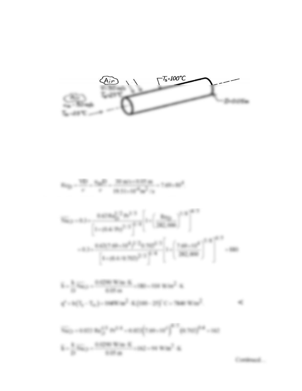
KNOWN: Surface temperature and diameter of a tube. Velocity and temperature of air in
cross flow. Velocity and temperature of air in fully developed internal flow.
FIND: Convection heat flux associated with the external and internal flows.
SCHEMATIC:
ASSUMPTIONS: (1) Steady-state conditions, (2) Uniform cylinder surface temperature, (3)
Fully developed internal flow, (4) For internal flow, air is an ideal gas with negligible viscous
dissipation and pressure variations.
PROPERTIES: Table A-4, Air (336 K): ν = 19.51 × 10⁻⁶ m2/s, k = 0.0290 W/m⋅K, Pr =
0.702.
ANALYSIS: For the external and internal flows,
From the Churchill-Bernstein relation for the external flow,
Hence, the convection coefficient and heat flux are
Using the Dittus-Boelter correlation, Eq. 8.60, for the internal flow, which is turbulent,

PROBLEM 8.37 (Cont.)
and the heat flux is
COMMENT: Convection effects associated with the two flow conditions are comparable.
PROBLEM 8.38
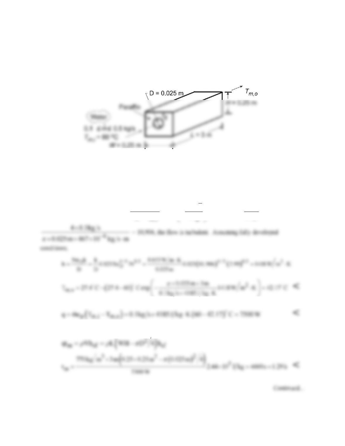
KNOWN: Length and diameter of tube submerged in paraffin of prescribed dimensions. Inlet
temperature and flow rate of water flowing through tube.
FIND: (a) Outlet temperature, heat rate, and time required for complete melting, and (b) Effect of
flowrate on operating conditions.
SCHEMATIC:
ASSUMPTIONS: (1) Negligible KE/PE and flow work changes for water, (2) Constant water
properties, (3) Negligible tube wall conduction resistance, (4) Negligible convection resistance in melt
(Ts =
T¥
= Tmp ), (5) Fully developed flow, (6) No heat loss to the surroundings.
PROPERTIES: Water (given): cp = 4.185 kJ/kg⋅K, k = 0.653 W/m⋅K, m = 467 × 10-6 kg/s⋅m, Pr = 2.99;
Paraffin (given): Tmp = 27.4°C, hsf = 244 kJ/kg, ρ = 770 kg/m3.
ANALYSIS: (a) From Eq. 8.41b,
m,o
m,i p
TT DLh
exp
T T mc
π
∞
∞
−= −
−
. With ReD =
4m
D
πm
=
From the overall energy balance,
Applying an energy balance to a control volume about the paraffin, Ein = ∆Est, the time tm required to
melt the paraffin is
PROBLEM 8.38 (Cont.)
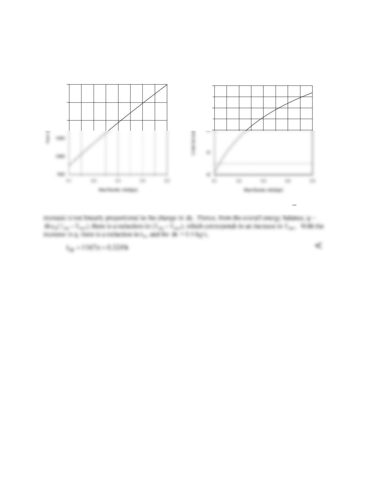
(b) The effect of
m
on q and Tm,o was determined by accessing the Correlations Toolpad of IHT, and
the results are plotted as follows.
20000
25000
30000
45
46
Although q increases with increasing
m
due to the attendant increase in ReD, and therefore
h
, the
m
m
COMMENTS: Heat transfer from the water to the paraffin is also affected by free convection in the
melt region around the tube. The effect is to decrease U, increase Ts, and decrease q with increasing
time. The actual time to achieve complete melting would exceed values computed in the foregoing
analysis.
PROBLEM 8.39
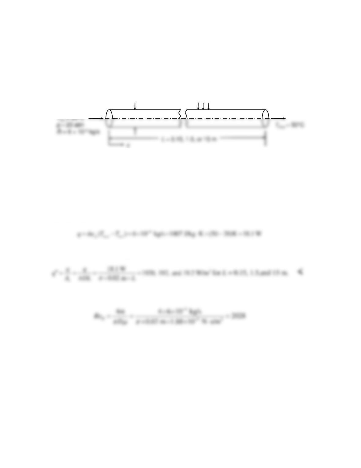
KNOWN: Mass flow rate, inlet temperature, and pressure of compressed air. Tube diameter. Surface
heat flux is constant. Outlet mean temperature.
FIND: Required surface heat flux and surface temperature at tube exit for three tube lengths.
SCHEMATIC:
D= 20 mm
Dry air
q
s
“
ASSUMPTIONS: (1) Steady-state conditions, (2) Constant properties, (3) Incompressible fluid with
negligible viscous dissipation.
PROPERTIES: Table A-4, Air, (T = 308 K):
m
= 1.88 × 10⁻⁵ N⋅s/m2, cp = 1007 J/kg⋅K, k = 0.0269
W/m⋅K , Pr = 0.706.
ANALYSIS: Equation 8.34 may be used to find the heat transfer rate needed to increase the temperature
from 20 to 50°C:
The heat flux for the three lengths can then be found:
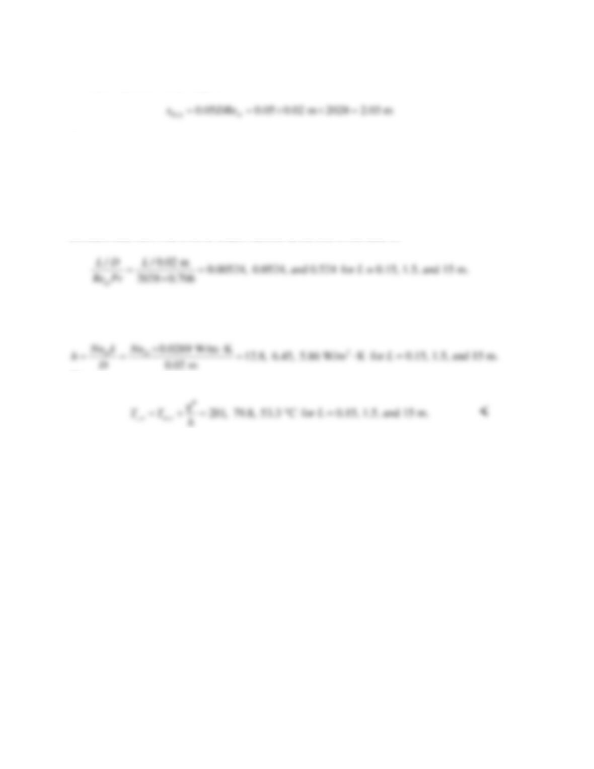
To find the surface temperature at the exit, we need to analyze the heat transfer. The Reynolds number is:
Continued…
PROBLEM 8.39 (Cont.)
The hydrodynamic entry length is:
Therefore the cases L = 0.15 m and L = 1.5 m have simultaneously developing velocity and
temperature or a “combined entry length.” (Note that as long as the velocity is not fully
developed, the temperature is also not fully developed.) The case L = 15 m has fully developed
velocity and temperature (the thermal entry length is shorter than the hydrodynamic entry length
since Pr < 1).
The local Nusselt number can be read off of Figure 8.10a for Pr = 0.7, combined entry length,
constant heat flux. The inverse Graetz number at the end of the tube is:
and the Nusselt numbers are approximately 9.5, 4.8, and 4.36 for the three tube lengths. The heat
transfer coefficients are:
Then,
COMMENTS: (1) Figure 8.10 cannot be read with great accuracy. (2) The heat transfer coefficient is
higher for a shorter tube because the boundary layer is thinner. This tends to keep the wall cooler.
However, the dominant effect is that shorter tubes require larger heat fluxes, and this results in higher
surface temperatures.
PROBLEM 8.40
KNOWN: Diameter and length of circular tube, liquid water flow rate, liquid water entrance
temperatures and tube surface temperatures.
FIND: Water outlet temperatures for (a) Tm,i = 500 K, Ts = 510 K and (b) Tm,i = 300 K, Ts = 310 K.
(c) Discuss whether the flow is laminar or turbulent for Tm,i = 300 K, Ts = 647 K.
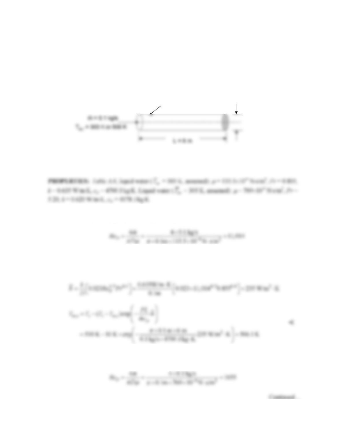
SCHEMATIC:
ASSUMPTIONS: (1) Steady–state conditions, (2) Constant properties in parts (a) and (b), (3)
Negligible viscous dissipation.
ANALYSIS: (a) We begin by calculating the Reynolds number
Therefore, the flow is in a fully turbulent condition. Since L/D = 6m/0.1m = 60, we conclude that
entrance effects are not important. We may use Dittus–Boelter (Eq. 8.60) to determine the average heat
transfer coefficient and the mean outlet temperature may be found from Eq. (8.41b).
(b) The Reynolds number is
D = 0.1 m
Liquid water
Ts= 310 K, 510 K or 647 K
D = 0.1 m
Liquid water
Ts= 310 K, 510 K or 647 K

PROBLEM 8.40 (Cont.)
Therefore, the flow is laminar. The thermal entrance length is xfd,t = 0.05 × D × ReD × Pr = 0.05 ×
0.1m × 1655 × 5.20 = 43.0 m > L. Therefore, we expect entrance effects to be significant. With Pr > 5,
we may use Eq. (8.57) with Eq. (8.56) for the Graetz number, to estimate the value of
h
.
Using Eq. (8.41b)
(c) The temperature variations within the water are very large. Therefore, properties are expected to
vary significantly from location to location. Near the entrance of the tube, average temperatures will
COMMENTS: Even though entrance effects are important for the laminar flow conditions of part
(b), the heat transfer coefficient is small relative to that associated with the turbulent conditions of part
(a).
PROBLEM 8.41
KNOWN: Gas turbine vane approximated as a tube of prescribed diameter and length maintained at a
known surface temperature. Air inlet temperature and flowrate.
FIND: (a) Outlet temperature of the air coolant for the prescribed conditions and (b) Compute and plot
the air outlet temperature Tm,o as a function of flow rate, 0.1 ≤
m
≤ 0.6 kg/h. Compare this result with
those for vanes having passage diameters of 2 and 4 mm.
SCHEMATIC:
ASSUMPTIONS: (1) Steady-state conditions, (2) Ideal gas with negligible viscous dissipation and
pressure variation.
PROPERTIES: Table A.4, Air (assume
m
T
= 780 K, 1 atm): cp = 1094 J/kg⋅K, k = 0.0563 W/m⋅K, m
= 363.7 × 10⁻⁷ N⋅s/m2, Pr = 0.706.
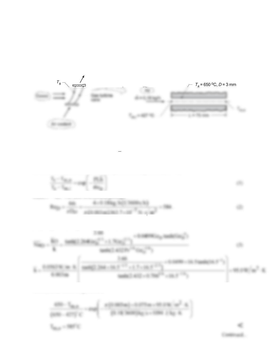
ANALYSIS: (a) For constant wall temperature heating, from Eq. 8.41b,
where P = πD. For flow in a circular passage,
( )
The flow is laminar, and from Eq. 8.3, xfd,h = 0.05ReDD = 88 mm. Thus, the flow is in the combined
entry length. From Eq. 8.56, GzD = (D/L)ReDPr = 16.5 and from Eq. 8.58,
Hence, the air outlet temperature is
PROBLEM 8.41 (Cont.)
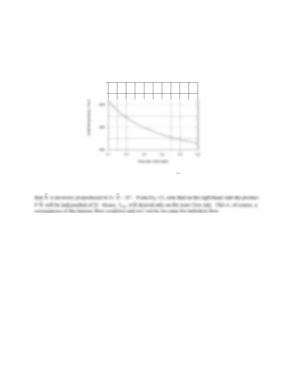
(b) Using the IHT Correlations Tool, Internal Flow, for Laminar Flow with combined entry length, along
with the energy balance and rate equations above, the outlet temperature Tm,o was calculated as a
function of flow rate for diameters of D = 2, 3 and 4 mm. The plot below shows that Tm,o decreases
strongly with increasing flow rate, but is independent of passage diameter.
650
COMMENTS: (1) Based upon the calculation for Tm,o = 585°C,
m
T
= 779 K which is in good
agreement with our assumption to evaluate the thermophysical properties. (2) Why is Tm,o independent
of D? Since ReD varies inversely with D, GzD is independent of D, and so is NuD. From Eq. (3), note
PROBLEM 8.42
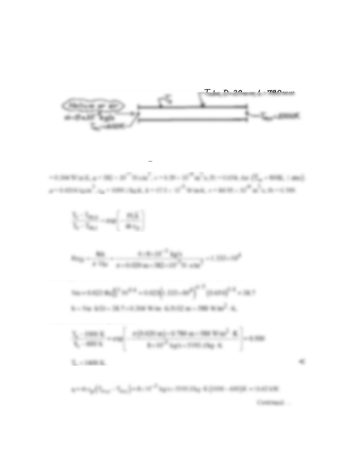
KNOWN: Gas-cooled nuclear reactor tube of 20 mm diameter and 780 mm length with helium
heated from 600 K to 1000 K at 8 × 10⁻³ kg/s.
FIND: (a) Uniform tube wall temperature required to heat the helium, (b) Outlet temperature and
required flow rate to achieve same removal rate and wall temperature if the coolant gas is air.
SCHEMATIC:
ASSUMPTIONS: (1) Steady-state conditions, (2) Ideal gas with negligible viscous dissipation and
pressure variation, (3) Fully developed conditions.
PROPERTIES: Table A-4, Helium
( )
m
T 800K, 1 atm :=
ρ = 0.06272 kg/m3, cp = 5193 J/kg⋅K, k
ANALYSIS: (a) For helium and a constant wall temperature, from Eq. 8.41b,
where P = πD. For the circular tube,
and using the Dittus–Boelter correlation for turbulent, fully developed flow,
Hence, the surface temperature is
s
The heat rate with helium coolant is
PROBLEM 8.42 (Cont.)
(b) For the same heat removal rate (q) and wall temperature (Ts) with air supplied at Tm,i, the
relevant relations are
where Tm,o and
m
are unknown. An iterative solution is required: assume a value of Tm,o and find
m
from Eq. (1); use
m
in Eqs. (3) and (4) to find
h
and then Eq. (2) to evaluate Tm,o; compare
results and iterate. Using thermophysical properties of air evaluated at
m
T
= 800K, the above
relations, written in the order they would be used in the iteration, become
Results of the iterative solution are
Trial Tm,o (K)
m
(kg/s)
()
2
a
h W/m K⋅
Tm,o (K)
(Assumed) Eq. (5) Eq. (6) Eq. (7)
1 1000 3.781 × 10⁻² 407 905
4 890 5.215 × 10⁻² 527 890
Hence, we find
COMMENTS: To achieve the same cooling rate with air, the required mass rate is 6.5 times that
obtained with helium.
PROBLEM 8.43
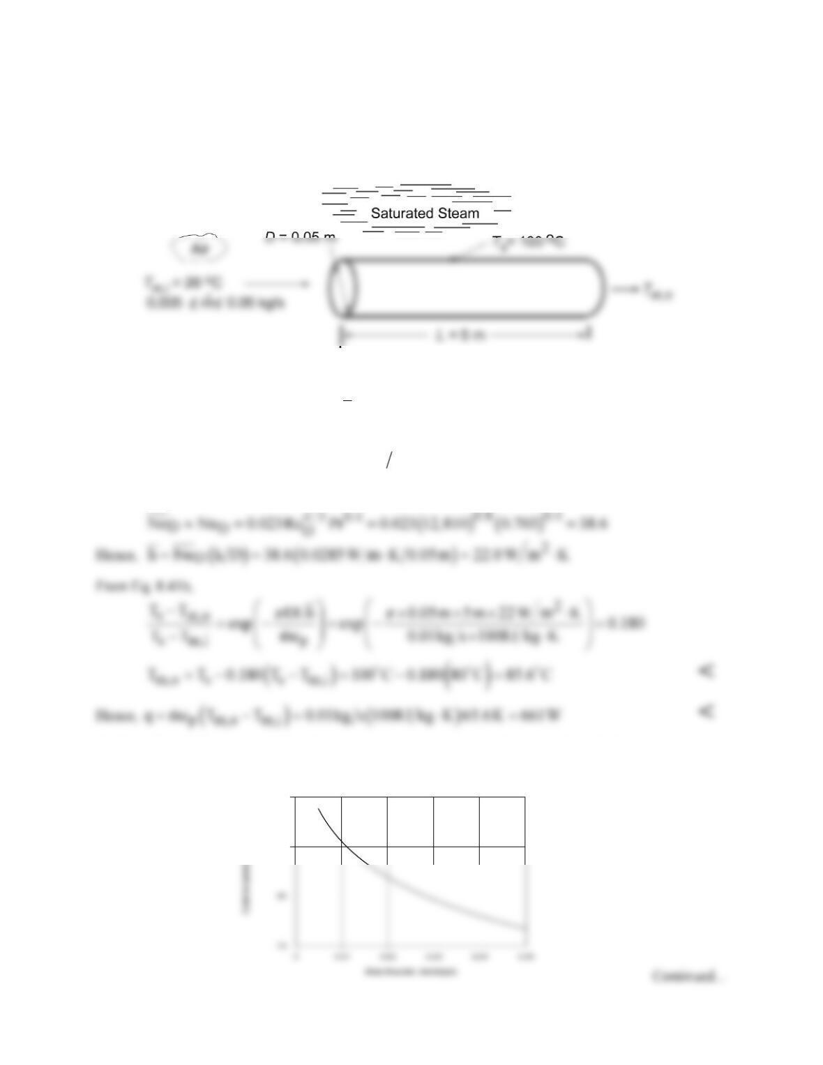
KNOWN: Diameter, length and surface temperature of tubes used to heat ambient air. Flow rate and
inlet temperature of air.
FIND: (a) Air outlet temperature and heat rate per tube, (b) Effect of flow rate on outlet temperature.
Design and operating conditions suitable for providing 1 kg/s of air at 75°C.
SCHEMATIC:
ASSUMPTIONS: (1) Steady-state, (2)Ideal gas with negligible viscous dissipation and pressure
variation, (3) Negligible tube wall thermal resistance.
PROPERTIES: Table A.4, air (assume
m
T
= 330 K): cp = 1008 J/kg⋅K, m = 198.8 × 10⁻⁷ N⋅s/m2, k =
0.0285 W/m⋅K, Pr = 0.703.
ANALYSIS: (a) For
m
= 0.01 kg/s, ReD =
4m D
πm
= 0.04 kg/s/π(0.05 m)198.8 × 10⁻⁷ N⋅s/m2 =
12,810. Hence, the flow is turbulent. If fully developed flow is assumed throughout the tube, the Dittus-
Boelter correlation may be used to obtain the average Nusselt number.
(b) The effect of flow rate on the outlet temperature was determined by using the IHT Correlations and
Properties Toolpads.
85
90

PROBLEM 8.43 (Cont.)
Although
h
and hence the heat rate increase with increasing
m
, the increase in q is not linearly
proportional to the increase in
m
and Tm,o decreases with increasing
m
.
A flow rate of
m
= 0.05 kg/s is not large enough to provide the desired outlet temperature of
75°C, and to achieve this value, a flow rate of 0.0678 kg/s would be needed. At such a flow rate,
amb
Nm m 1kg / s+=
m
COMMENTS: With L/D = 5 m/0.05 m = 100, the assumption of fully developed conditions
throughout the tube is reasonable.
PROBLEM 8.44
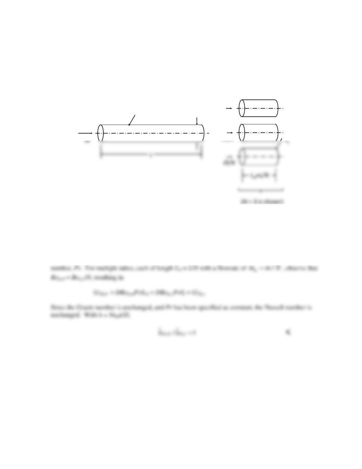
KNOWN: Length of a tube with constant surface temperature and a combined entrance length, L <
xfd,t.
FIND: Expression for the ratio of the average heat transfer coefficient for N tubes each of length LN =
L/N to the average coefficient for the single tube.
SCHEMATIC:
TsD
•
m/N
•
m/N
•
ASSUMPTIONS: (1) Combined entrance conditions, (2) Constant properties, (3) Negligible viscous
dissipation.
PROPERTIES: Given: Pr = 4.
ANALYSIS: The Nusselt number for the combined entrance problem with 0.1 < Pr < 5 is given by
Equation 8.58 and is seen to be a function of the Graetz number, GzD = DReDPr/L, and the Prandtl
COMMENTS: (1) Breaking the tube into shorter lengths has no impact on the overall heat transfer
rate. Shortening the tube will, in general, tend to increase the average heat transfer coefficient, but this
effect is offset by reduction of the flow rate in each of the shorter tubes. The scheme would not result
in any heat transfer enhancement. (2) The same result holds for the thermal entrance problem, since
the Nusselt number is also a function only of GzD.
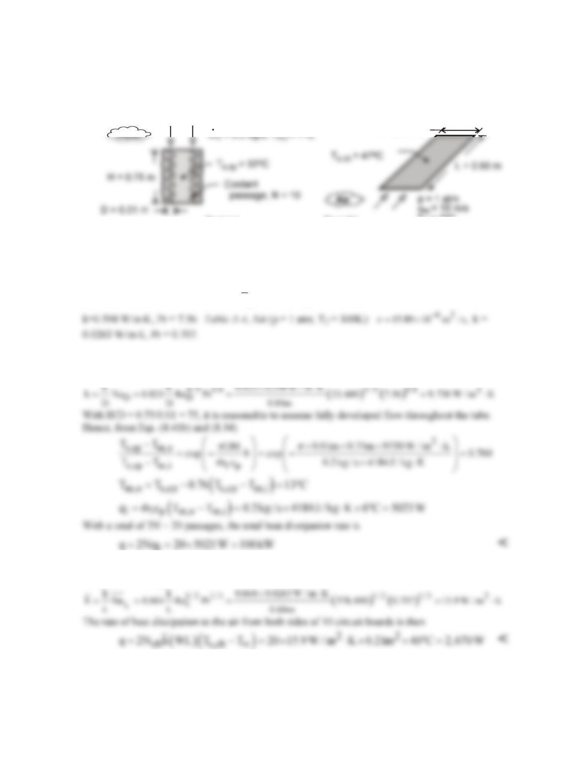
PROBLEM 8.45
KNOWN: Cold plate geometry and temperature. Inlet temperature and flow rate of water. Number
of circuit boards and temperature and velocity of air in parallel flow over boards.
FIND: (a) Rate of heat dissipation by cold plates, (b) Rate of heat dissipation by air flow.
SCHEMATIC:
Part (a) Part (b)
T = 7 C
o
oo
W = 0.35 m
ASSUMPTIONS: (1) Isothermal cold plate, (2) All heated generated by circuit boards is dissipated
by cold plates (Part (a)), (3) Circuit boards may be represented as isothermal at an average surface
temperature, (4) Air flow over circuit boards approximates that over a flat plate in parallel flow, (5)
Steady operation, (6) Constant properties, (7) Water is incompressible liquid with negligible viscous
dissipation.
PROPERTIES: Table A-6, Water
( )
m
T 290K :≈
cp = 4184 J/kg⋅K,
62
1080 10 N s / m ,
m
−
=×⋅
ANALYSIS: (a) With
62
D1
Re 4 m / D 4 0.2 kg / s / 0.01m 1080 10 N s / m 23, 600,
πm π
−
= =× × ×× ⋅ =
the
flow is turbulent, and from Eq. (8.60),
1
(b) For the air flow,
62
D
Re u L / 10 m / s 0.60m / 15.89 10 m s 378, 000,
ν
−
∞
==× ×=
and the flow is
laminar. From Eq. (7.30),
COMMENTS: The cooling capacity of the cold plates far exceeds that of the air flow. However, the
challenge would be one of efficiently transferring such a large amount of energy to the cold plates
without incurring excessive temperatures on the circuit boards.
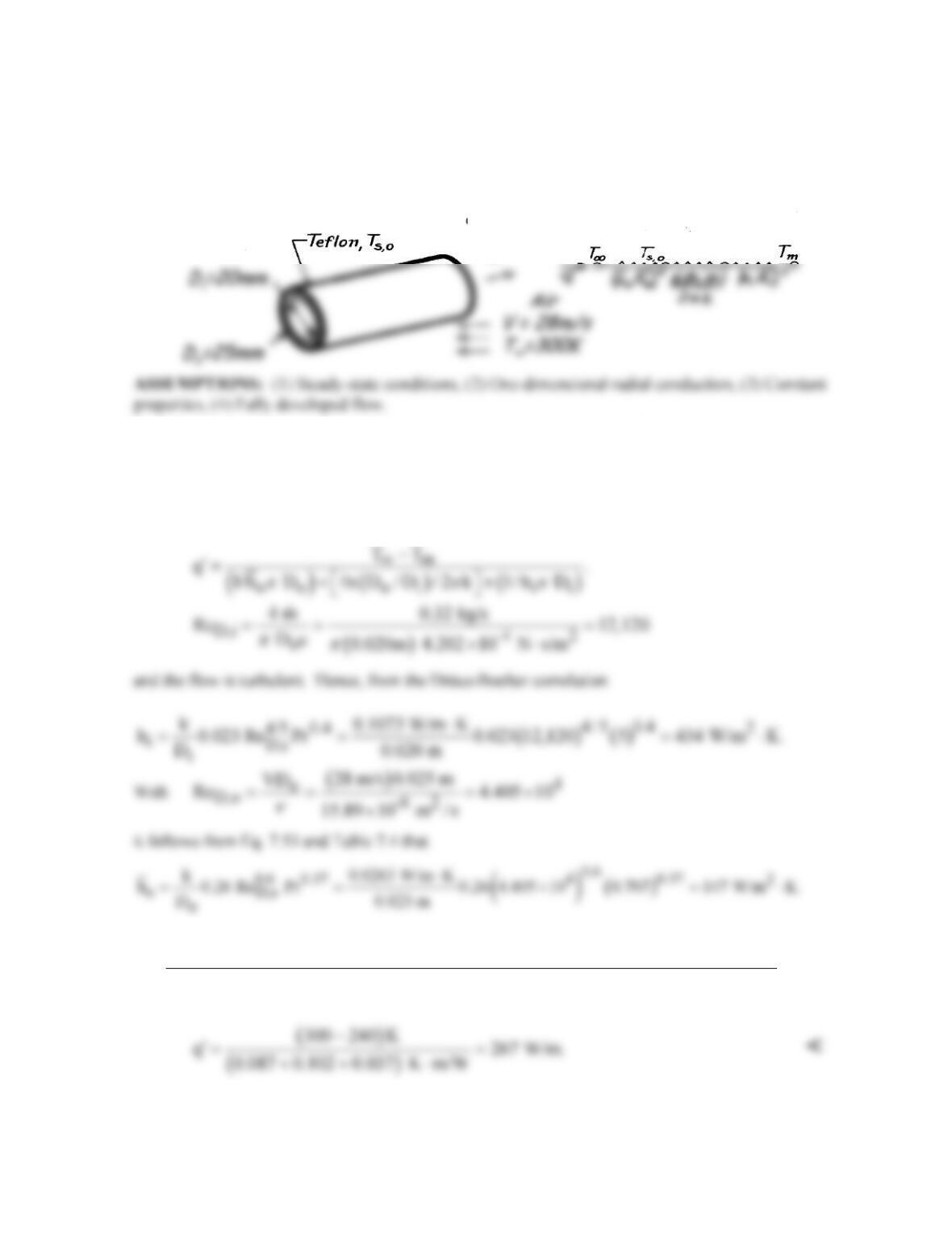
Freon
m=0.08 kg/s
T
m
=240K
.
R134a
PROBLEM 8.46
KNOWN: Flow rate and temperature of Refrigerant–134a passing through a Teflon tube of
prescribed inner and outer diameter. Velocity and temperature of air in cross flow over tube.
FIND: Heat transfer rate per unit tube length.
SCHEMATIC:
PROPERTIES: Table A-4, Air (T = 300 K, 1 atm): ν = 15.89 × 10⁻⁶ m2/s, k = 0.0263 W/m⋅K, Pr =
0.707; Table A-5, R-134a (T = 240 K): m = 4.202 × 10⁻⁴ N⋅s/m2, k = 0.1073 W/m⋅K, Pr = 5.0; Table
A-3, Teflon (T ≈ 300 K): k = 0.35 W/m⋅K.
ANALYSIS: Considering the thermal circuit shown above, the heat rate is
Hence
()
( ) ( )
()
m
11
22
TT
q
147 W/m K 0.025 m n 25/20 / 2 0.350 W/m K 434 W/m K 0.020 m
ππ π
∞
−−
−
′=
⋅ + ⋅+ ⋅
COMMENTS: The three thermal resistances are comparable, with the conduction resistance being
the largest. Note that Ts,o = T∞ – q′/hoπDo = 300K – 267 W/m/147 W/m2⋅K π 0.025 m = 277 K.
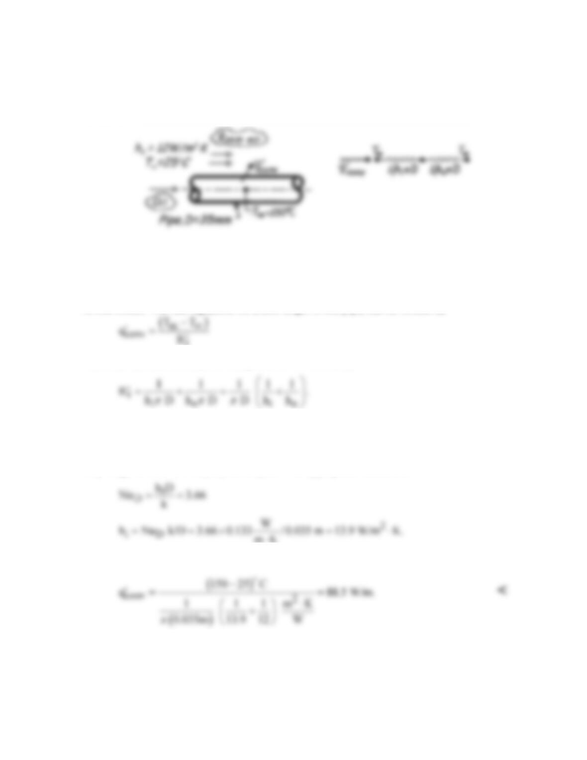
PROBLEM 8.47
KNOWN: Oil flowing slowly through a long, thin-walled pipe suspended in a room.
FIND: Rate of heat loss per unit length of the pipe,
conv
q.
′
SCHEMATIC:
ASSUMPTIONS: (1) Steady-state conditions, (2) Tube wall thermal resistance negligible,
(3) Fully developed flow, (4) Radiation exchange between pipe and room negligible.
PROPERTIES: Table A-5, Unused engine oil (Tm = 150°C = 423K): k = 0.133 W/m⋅K.
ANALYSIS: The rate equation, for a unit length of the pipe, can be written as
where the thermal resistance is comprised of two elements,
The convection coefficient for internal flow, hi, must be estimated from an appropriate
correlation. From practical considerations, we recognize that the oil flow rate cannot be large
enough to achieve turbulent flow conditions. Hence, the flow is laminar, and if the pipe is
very long, the flow will be fully developed. The appropriate correlation is
mK
⋅
The heat rate per unit length of the pipe is
COMMENTS: This problem requires making a judgment that the oil flow will be laminar
rather than turbulent. Why is this a reasonable assumption? Recognize that the correlation
applies to a constant surface temperature condition.
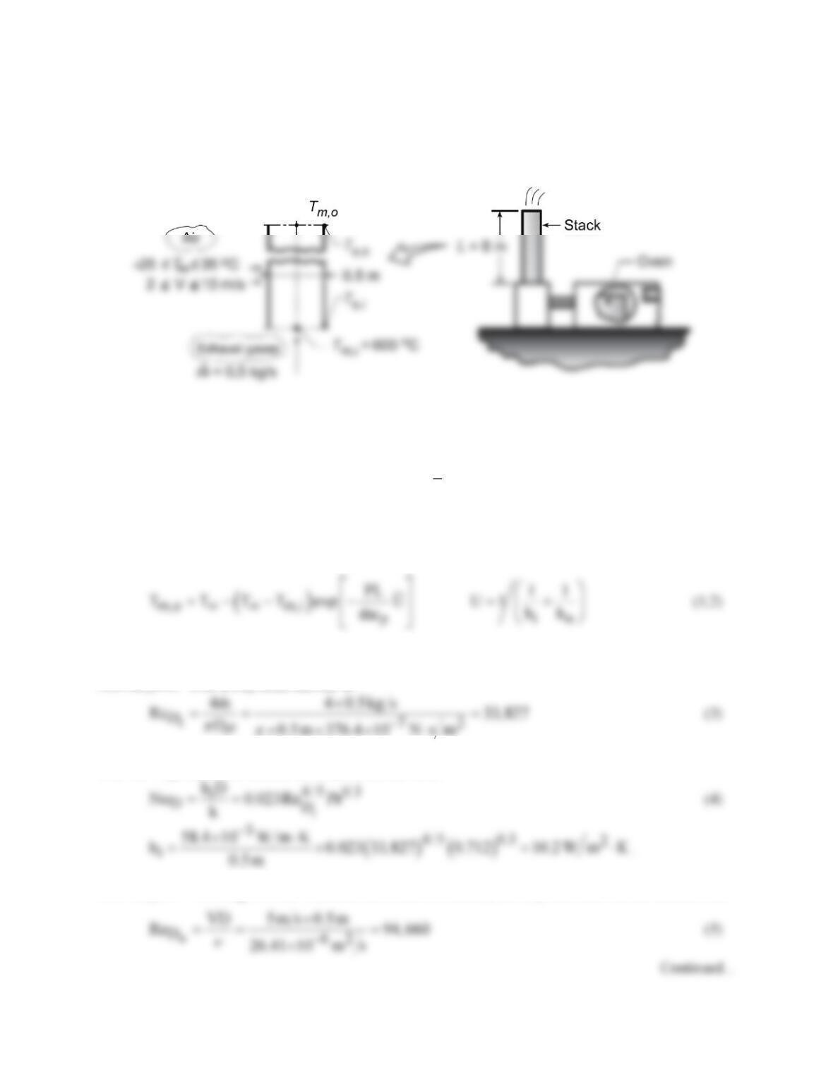
PROBLEM 8.48
KNOWN: Thin-walled, tall stack discharging exhaust gases from an oven into the environment.
FIND: (a) Outlet gas and stack surface temperatures, Tm,o and Ts,o, and (b) Effect of wind temperature
and velocity on Tm,o .
SCHEMATIC:
ASSUMPTIONS: (1) Steady-state conditions, (2) Wall thermal resistance negligible, (3) Exhaust gas
properties approximated as those of atmospheric air, (4) Radiative exchange with surroundings
negligible, (5) Ideal gas with negligible viscous dissipation and pressure variation, (6) Fully developed
flow, (7) Constant properties.
PROPERTIES: Table A.4, air (assume Tm,o = 773 K,
m
T
= 823 K, 1 atm): cp = 1104 J/kg⋅K, m =
376.4 × 10⁻⁷ N⋅s/m2, k = 0.0584 W/m⋅K, Pr = 0.712; Table A.4, air (assume Ts = 523 K,
T¥
= 4°C = 277
K, Tf = 400 K, 1 atm): ν = 26.41 × 10⁻⁶ m2/s, k = 0.0338 W/m⋅K, Pr = 0.690.
ANALYSIS: (a) From Eq. 8.45a,
where hi and ho are average coefficients for internal and external flow, respectively.
Internal flow: With a Reynolds number of
the flow is turbulent. Considering the flow to be fully developed throughout the stack (L/D = 12) and
with Ts < Tm, the Dittus–Boelter correlation has the form
External flow: Working with the Churchill/Bernstein correlation, the Reynolds and Nusselt numbers are
PROBLEM 8.48 (Cont.)
Hence,
( )
2
o
h 0.0338 W m K 0.5 m 205 13.9 W m K= ⋅ ×= ⋅
(6)
The outlet gas temperature is then
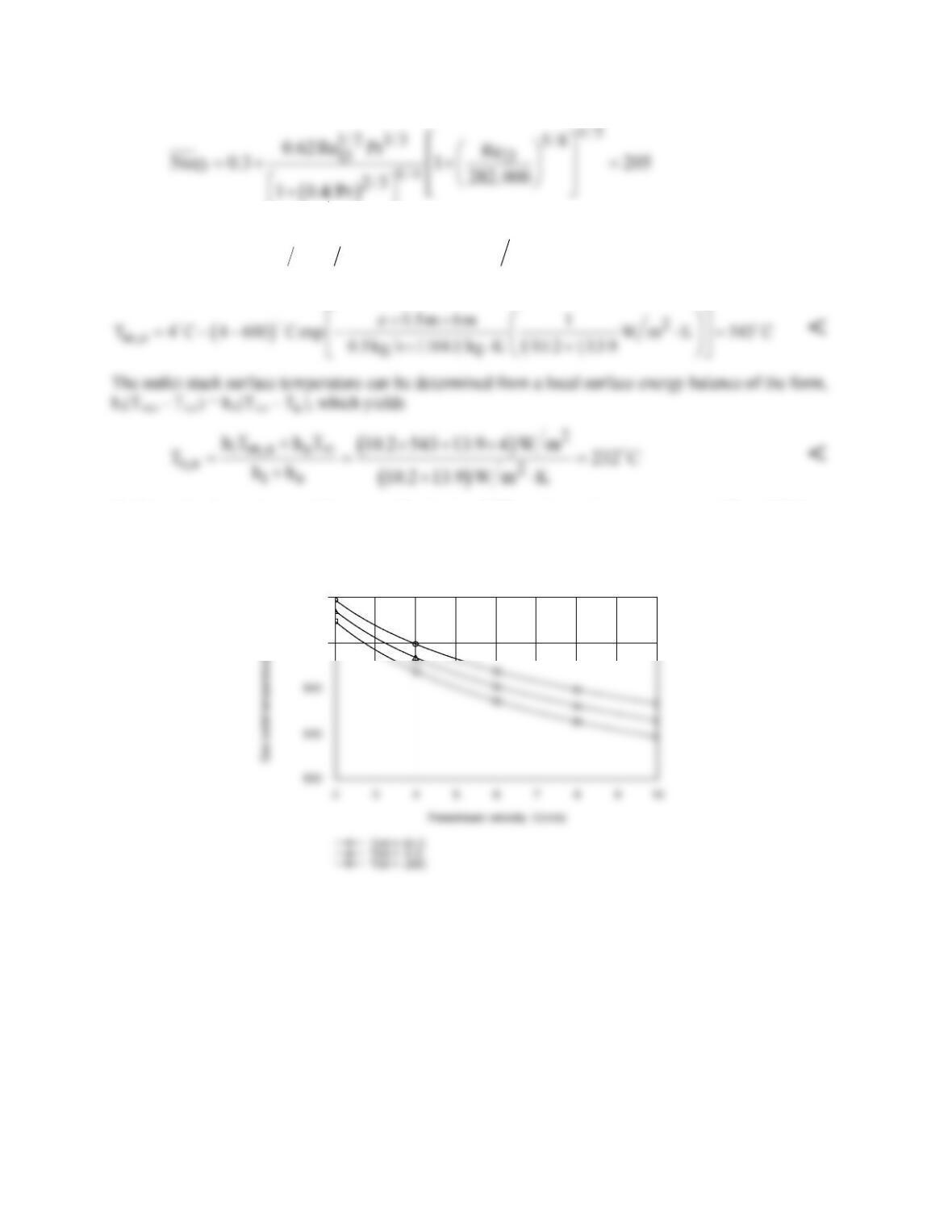
(b) Using the Correlations and Properties Toolpads of IHT, with a surface temperature of Ts = 523 K
assumed solely for the purpose of evaluating properties associated with airflow over the cylinder, the
following results were generated.
550
560
Due to the elevated temperatures of the gas, the variation in ambient temperature has only a small effect
on the gas exit temperature. However, the effect of the freestream velocity is more pronounced.
Discharge temperatures of approximately 530 and 560°C would be representative of cold/windy and
warm/still atmospheric conditions, respectively.
COMMENTS: If there are constituents in the discharge gas flow that condense or precipitate out at
temperatures below Ts,o, this operating condition should be avoided.