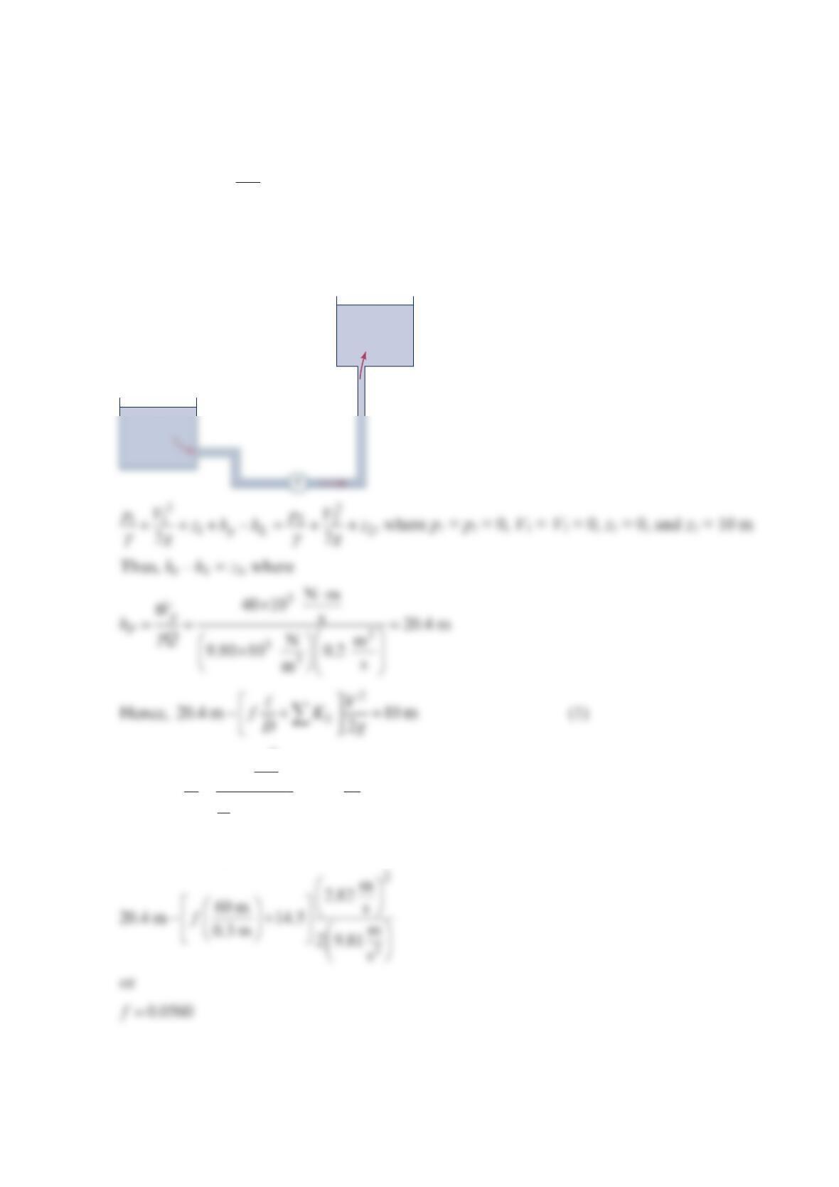
Problem 8.80
Water is pumped through a
6
0-m-long, 0.3-m-diameter pipe from a lower reservoir to a
higher reservoir whose surface is
1
0 m above the lower one. The sum of the minor loss
coefficients for the system is KL = 14.5. When the pump adds 40 kW to the water the
flowrate is
3
m
0.20 s. Determine the pipe roughness.
Solution 8.80
with
3
2
m
0.2 m
s2.82 s
(0.3 m)
4
Q
V
A
π
== =
Thus, from Eq. (1)
(1)
•
(2)
•
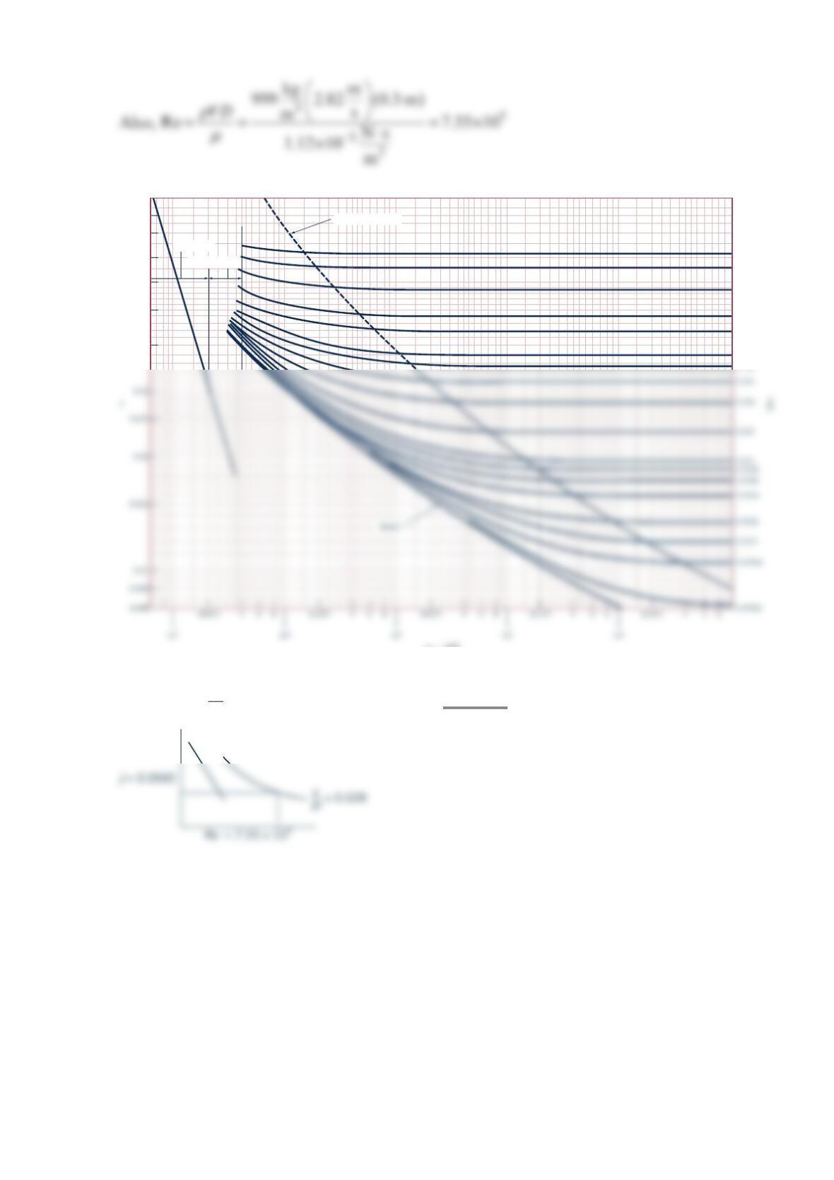
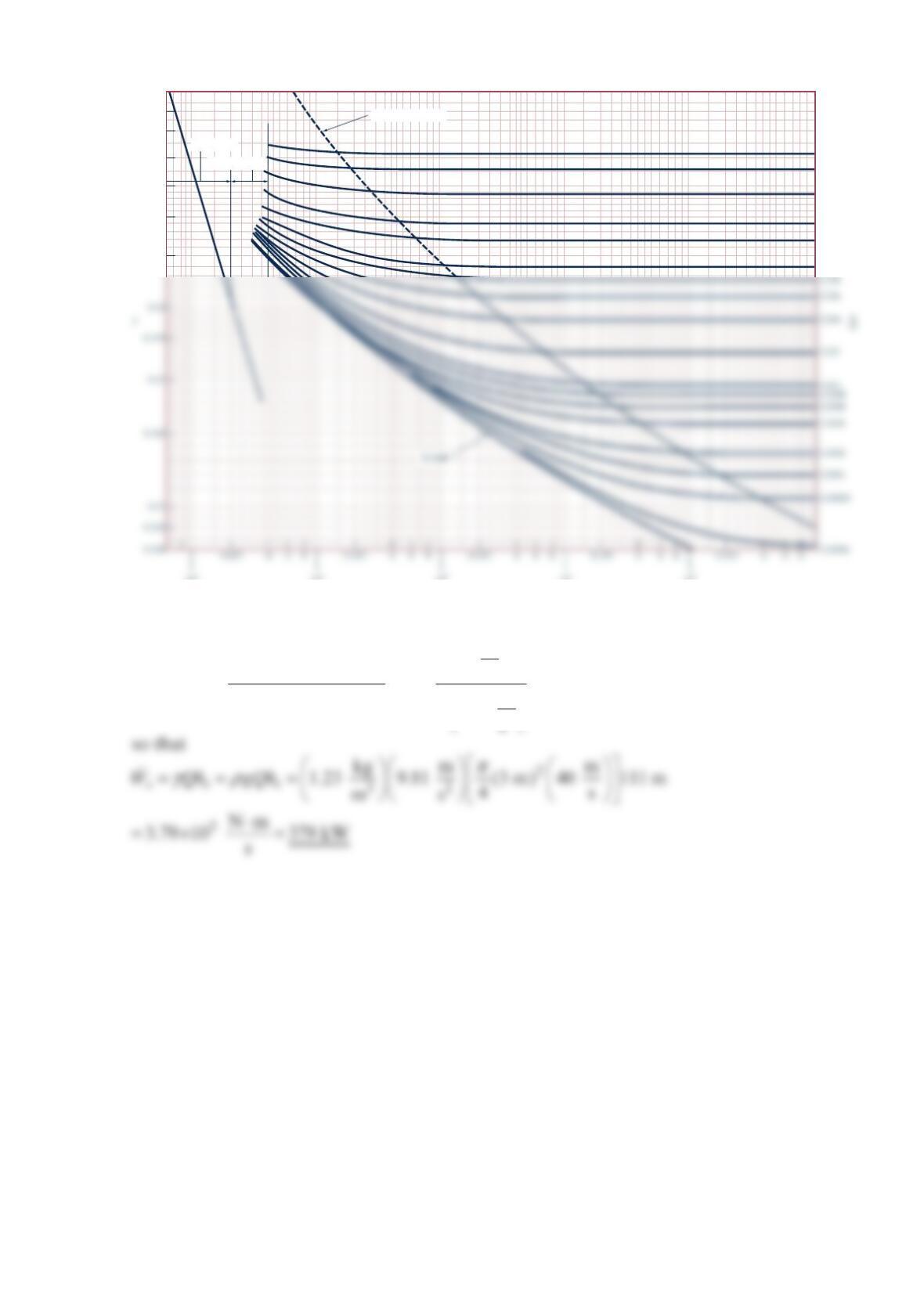
Thus, from the Moody chart (see the figure above) with Re = 7.55 × 10⁵ and f = 0.0560, it
follows that 0.028
D
ε
=, or
ε
= 0.028(0.3 m) = 0.0084 m
Transition range
Laminar flow
Wholly turbulent flow
0.1
0.09
0.08
0.07
0.06
0.05
0.04
0.05
0.04
0.03
0.02
0.015
0.01
0.008
Re = VD
_____
μ
ρ
Problem 8.81
Natural gas −
==×
2
5
3
slugs ft
0.0044 and 5.2 10
s
ft v
ρ
is pumped through a horizontal 6-in.–
diameter cast-iron pipe at a rate of lb
8
00 hr . If the pressure at section (1) is 50 psi (abs),
determine the pressure at section (2)
8
mi downstream if the flow is assumed
incompressible. Is the incompressible assumption reasonable? Explain.
Solution 8.81
22
2
11 2 2
12
222
pV p V V
zzf
ggDg
γγ
++=+++
, where z1 = z2, and V1 = V2 (1)
==
0.00085 ft 0.0017
6ft
12
D
ε
(from Table B.1 Equivalent Roughness for New Pipes [Adapted
from Moody (Ref. 7) and Colebrook (Ref. 8)])
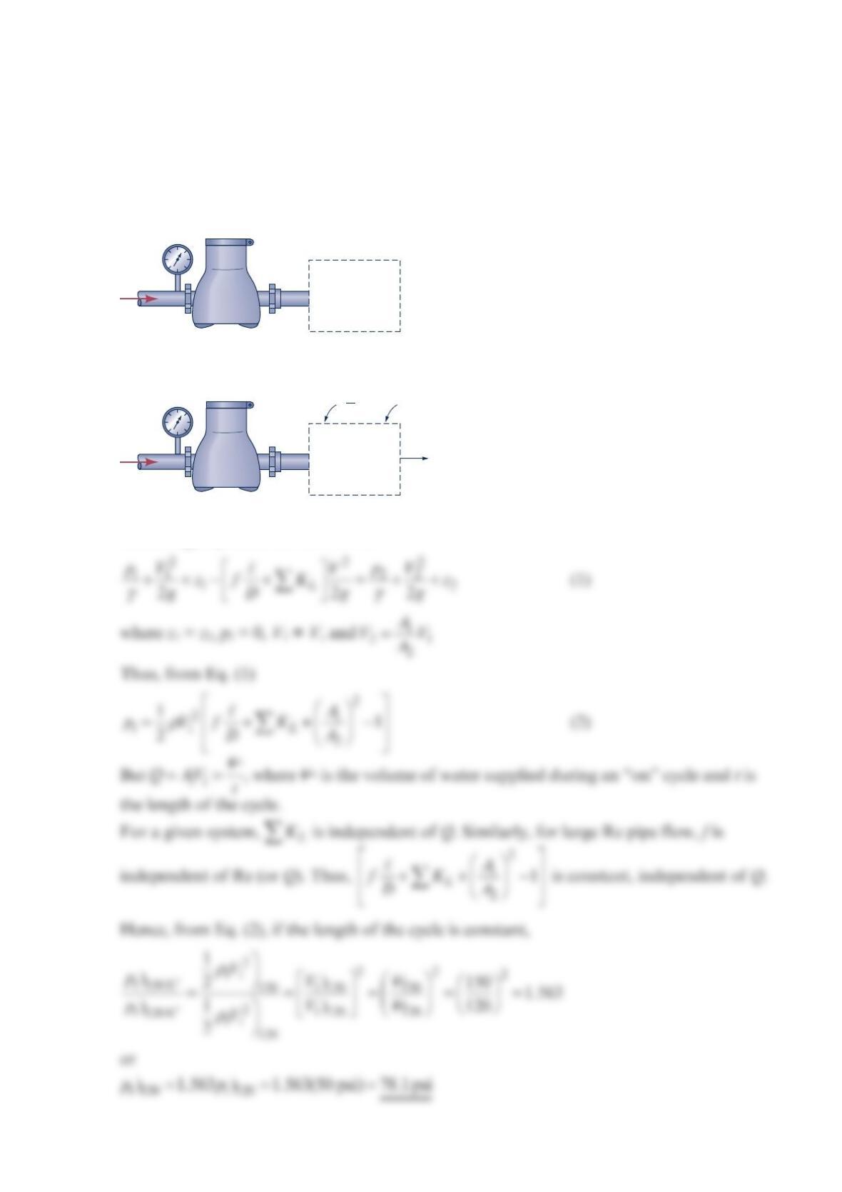
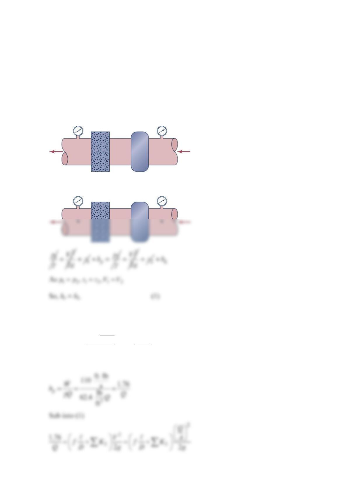
Problem 8.82
As shown in the figure below, a standard household water meter is incorporated into a lawn
irrigation system to measure the volume of water applied to the lawn. Note that these
meters measure volume, not volume flowrate. With an upstream pressure of p1 = 50 psi, the
meter registered that 120 ft3 of water was delivered to the lawn during an “on” cycle.
Estimate the upstream pressure, p1, needed if it is desired to have 150 ft3 delivered during an
“on” cycle. List any assumptions needed to arrive at your answer.
Solution 8.82
The energy equation for this flow is
(1)
Irrigation
system:
pipes, fittings,
nozzles, etc.
WATER
METER
(1)
(2)
Irrigation
system:
pipes, fittings,
nozzles, etc.
•
WATER
METER
f
D
V
2
K
L
ℓ
Σ
Problem 8.83
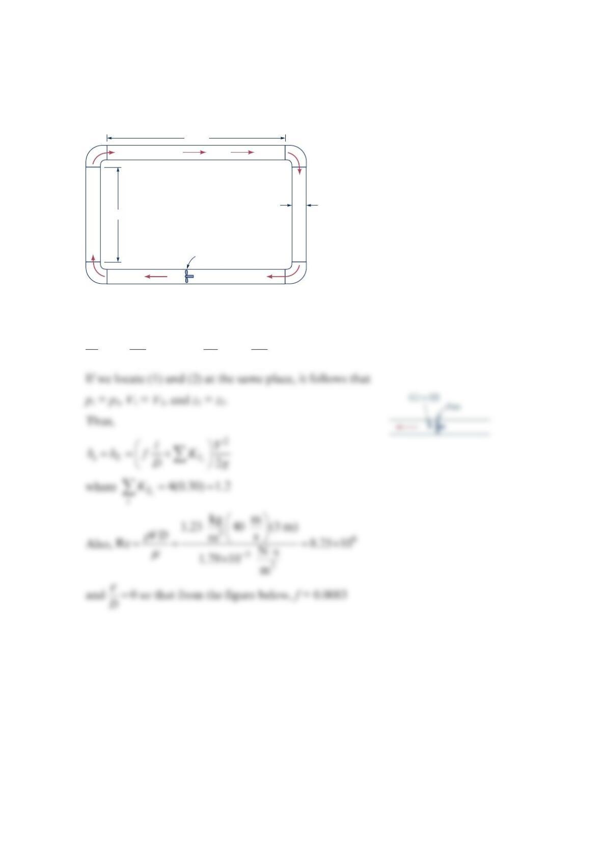
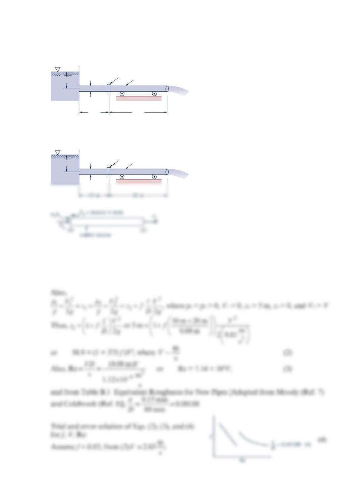
A fan is to produce a constant air speed of 40 m/s throughout the pipe loop shown in the
figure below. The 3-m-diameter pipes are smooth, and each of the four 90° elbows has a
loss coefficient of 0.30. Determine the power that the fan adds to the air.
Solution 8.83
22
11 2 2
12
22
Ls
pV p V
zhhz
gg
γγ
++ − + = + +
Fan
V
= 40 m/s
D
= 3 m
10 m
20 m
Hence,
2
2
m
40
(20201010) m s
0.0083 1.2 111 m
m
3 m 29.81
s
h
+++
=+=
Transition range
Laminar flow
Wholly turbulent flow
0.1
0.09
0.08
0.07
0.06
0.05
0.04
103
104
105
106
107
0.05
0.04
0.03
0.02
0.015
0.01
Re = VD
_____
μ
ρ
Problem 8.84
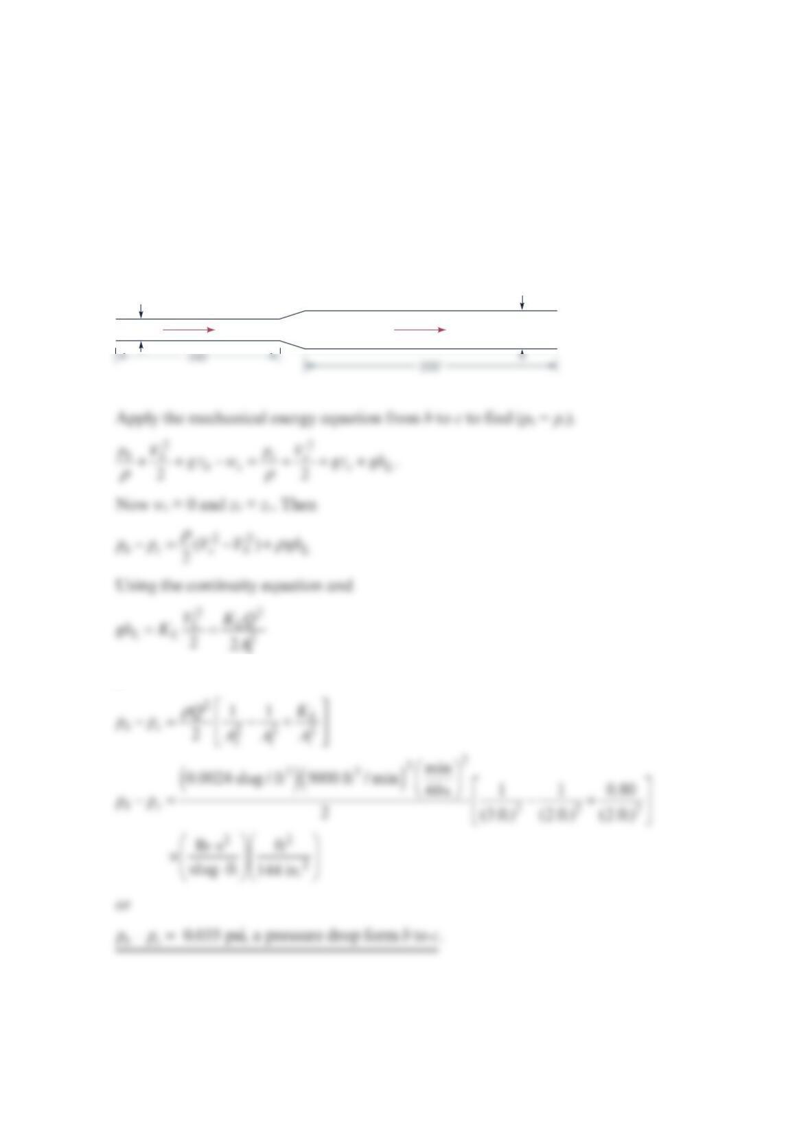
Air flows in a horizontal 100-ft-long, 24-in.× 24-in. duct at the rate of 5000 ft3/min. The air
then flows through an expansion into 200 ft of 36-in.× 36-in. duct. The expansion has a loss
coefficient of 0.80, based on the higher inlet velocity. Calculate the static pressure change
across the expansion and the static pressure loss across the entire duct system. The duct is
made of galvanized sheet metal. Use a constant air density of 0.0024 slug/ft3.
Solution 8.84
gives
Note that there is a static pressure drop since the friction losses give a pressure loss greater
than the static pressure rise due to the decrease in velocity. To find pa–pd, apply the
mechanical energy equation from a to d.
GALVANIZED SHEET METAL
A2 = 36
″
×
36
″
V2
A1 = 24
″
×
24
″
V1
abc
d
2
2
.
22
aa dd
as d L
V
pV p
gz w gz gh
ρρ
++ −=++ +
Now ws = 0, za = zb. Then
21
The mechanical energy equation becomes
Assuming standard air with v = 1.57 × 10⁻⁴ 2
f
t/s, the Reynolds numbers are:
()
3
5
11 1
1242
1
min
5000 ft / min (2 ft) 60 s
Re 2.65 10
(2 ft) (1. ft57 10 / s)
VD QD
vAv −
=== =×
×
and
The absolute roughness for galvanized sheet metal (taken as galvanized iron) is found from
Table 8.1 to be
ε
= 0.0005 ft. Then
1
1
0.0005 ft 0.00025
2ftD
ε
==
and 2
2
0.0005 ft 0.00017
3ftD
ε
==
=– 0.00385 psi
ad
p
p
p
Problem 8.85
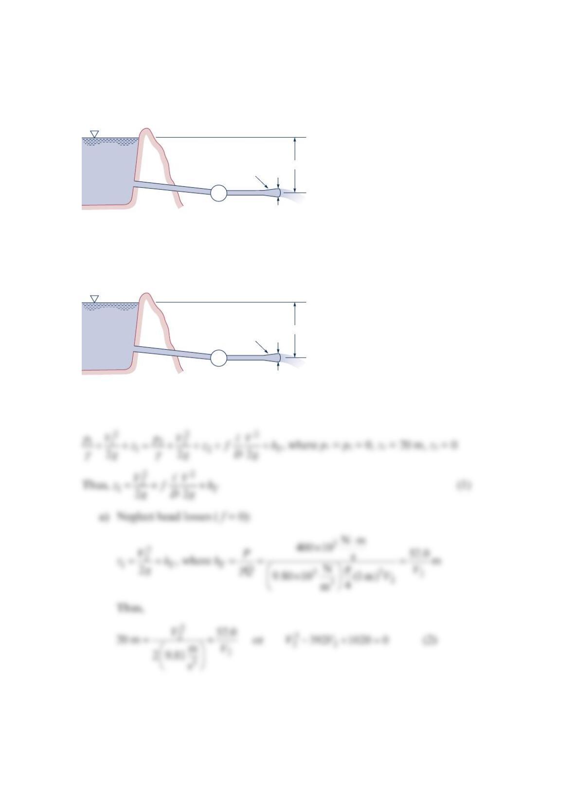
The turbine shown in the figure below develops 400 kW. Determine the flowrate if (a) head
losses are negligible or (b) head loss due to friction in the pipe is considered. Assume
f = 0.02. Note: There may be more than one solution or there may be no solution to this
problem.
Solution 8.85
120 m of 0.30-m-diameter
cast-iron pipe
1 m
20 m
Diffuser
T
120 m of 0.30-m-diameter
cast-iron pipe
(1)
•
(2)
1 m
20 m
Diffuser
T
•
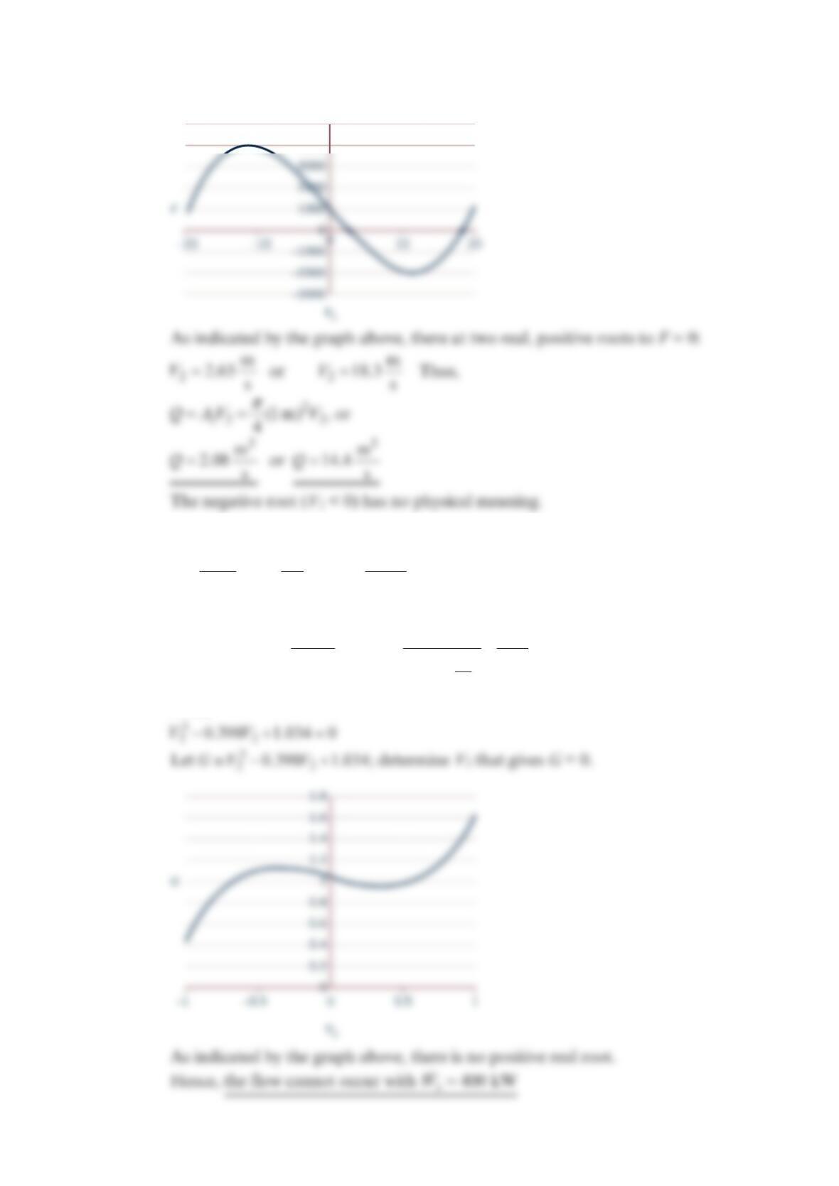
Determine the roots of this cubic equation. Let 3
22
392 1020
V
VF−+≡
b) Include head loss ( f = 0.02): From Eq. (1)
2
2
22 2
22 2
1m 11.1
0.3 m
VA D
V
VV V
AD
== = =
or
2
22
2
2
120 m 52.0
2
0 m 1 0.02 (11.1) m
m
0.3 m 29.81
s
V
V
=+ +
Thus,
V
5000
4000
Problem 8.86
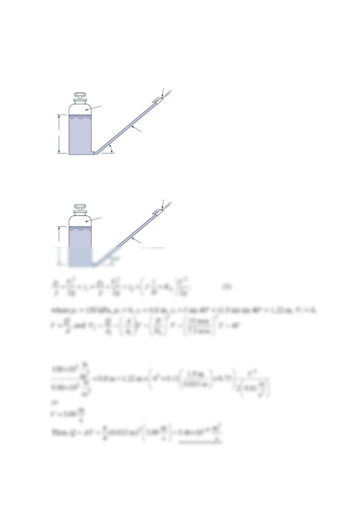
Water flows from the nozzle attached to the spray tank shown in the figure below.
Determine the flowrate if the loss coefficient for the nozzle (based on upstream conditions)
is 0.75 and the friction factor for the rough hose is 0.11.
Solution 8.86
Thus, with f = 0.11 and KL = 0.75 Eq. (1) gives
Nozzle diameter
= 7.5 mm
0.80 m
p
= 150 kPa
D
= 15 mm
𝓵
= 1.9 m
40
°
Nozzle diameter
= 7.5 mm
0.80 m
(1)
•
p
= 150 kPa
D
= 15 mm
•
(2)
Problem 8.87
Water flows through the pipe shown in the figure below. Determine the net tension in the
bolts if minor losses are neglected and the wheels on which the pipe rests are frictionless.
Solution 8.87
Application of the momentum equation to the control volume indicated gives
33 2 3
()0
B
p
AF mVV−= − =
, since 23
V
V=
Thus, FB = p3A3 (1)
80 mm
3.0 m
Bolts
Galvanized iron
20 m10 m
80 mm
3.0 m
Bolts
Galvanized iron
(1)
•
•
(2)
•
(3)
from (3) Re = 1.88 × 5
1
0; from (4) f = 0.0245 ≠ 0.02. Try again.
Assume 0.0245
f
=, or m
2.40 s
V
=, Re = 1.72 × 5
1
0 or f = 0.0245 Checks.
Thus, m
2.40 s
V
=
Problem 8.88
When the pump shown in the figure below adds 0.2 hp to the flowing water, the pressures
indicated by the two gages are equal. Determine the flowrate.
Length of pipe between gages = 60 ft
Pipe diameter = 0.1 ft
Pipe friction factor = 0.03
Filter loss coefficient = 12
Solution 8.88
The pump adds 0.2 hp of power.
ft lb
550 ft lb
s
0.2 hp 110
1 hp s
W
⋅
⋅
=× =
Convert to head by:
PumpFilter
PumpFilter
(2)
(1)
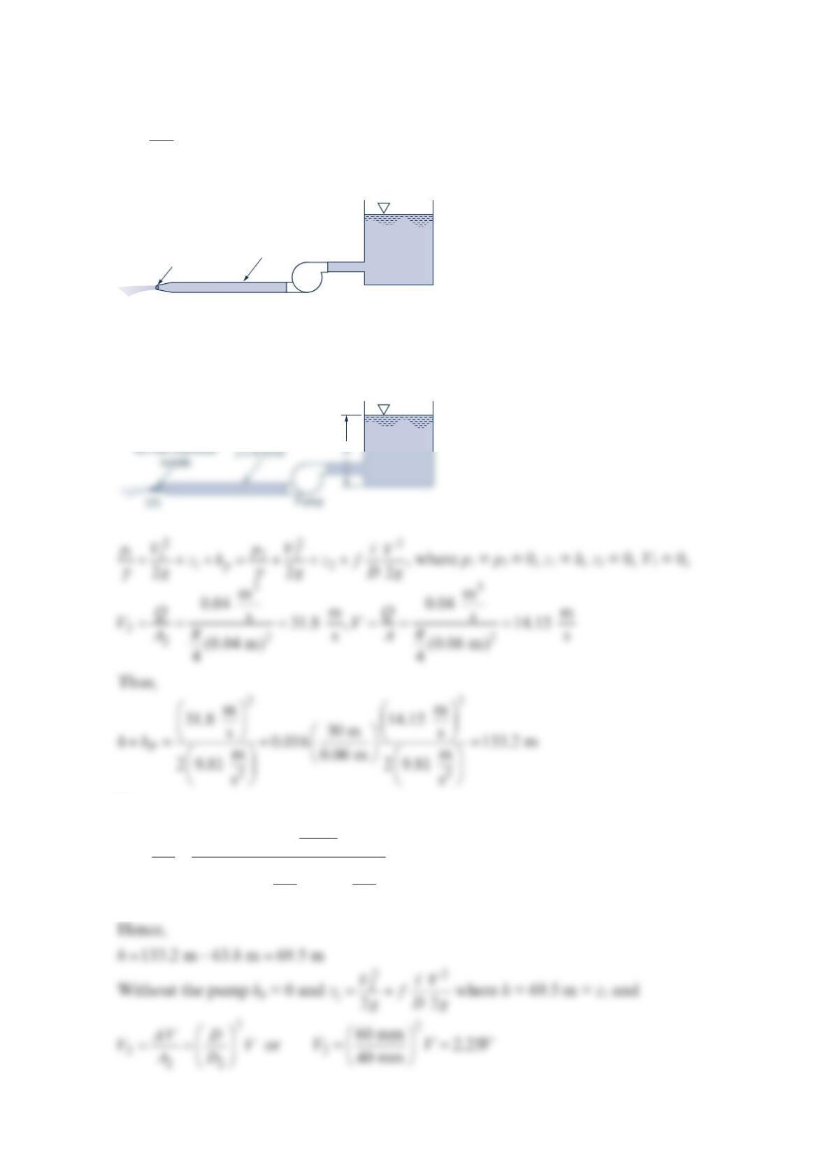
Problem 8.89
The pump shown in the figure below adds 25 kW to the water and causes a flowrate of
3
m
0.04 s. Determine the flowrate expected if the pump is removed from the system. Assume
f = 0.016 for either case and neglect minor losses.
Solution 8.89
But,
3
3
3
3
Nm
25 10 s63.8 m
Nm
9.80 10 0.04
s
m
P
P
h
Q
γ
⋅
×
== =
×
40-mm-diameter
nozzle
60-mm-diameter,
30-m-long pipe;
f
= 0.016
Pump
60-mm-diameter,
30-m-long pipe;
(1)
•
Thus,
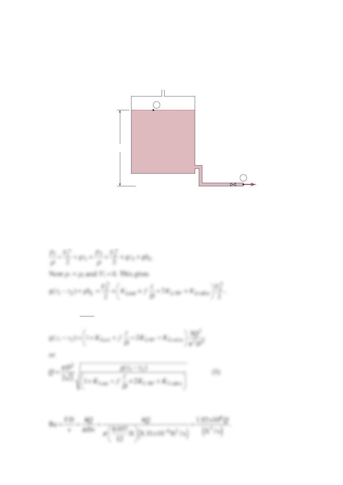
Problem 8.90
The vented storage tank shown in the figure below is used to refuel race cars at a race track.
A total of 40 ft of steel pipe (I.D. = 0.957 in.), two 90° regular elbows, and a globe valve
make up the system. Calculate the time needed to put 20 gal of fuel in a car tank. The
pressures, p2 and p1, are equal, the connections are threaded, and the fuel has the properties
of 68 °F normal octane (
ν
= 8.31×10⁻⁶ ft2/s).
Solution 8.90
Assume constant fluid density and apply the mechanical energy equation from point 1 to
point 2. No work is done.
Since 22
4Q
VD
π
=,
Figure 8.22 gives KLent = 0.5, and Table 8.2 gives KL 90° = 1.5 and KLvalve = 10, the Reynolds
number is
h
= 12 ft
Vent
Racing fuel
1
2
p2
=
patm
patm
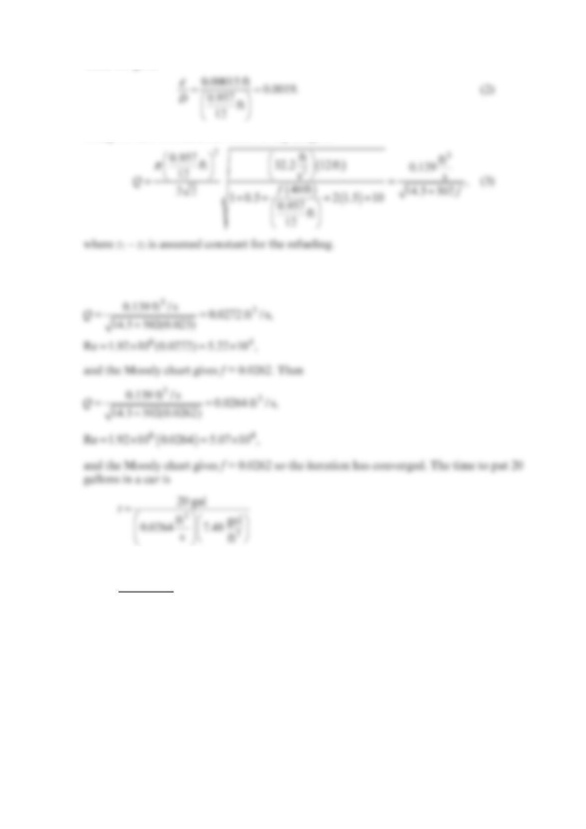
Table 8.1 gives
Using the known numerical values in Eq. (1) gives
Equations (2) and (3) are now solved with the Moody chart for Q. Using a trial and error
procedure, guess f = 0.023 = wholly turbulent value. Then
or
t = 101.3 s.